
Abstract
Eddy current testing is one of electromagnetic methods that are suitable for the inspection of conductive materials. Compared to regular flat coil, rectangular vertical coil can induce a more uniform eddy current distribution in the plate. With other advantages such as directional properties and less sensitive to lift-off variations, the rectangular vertical coil is considered superior to the flat one in certain applications. However, the eddy current of the conventional rectangular vertical coil is comparatively low as the weak coupling between the coil and the conducting plate. It is challenging to achieve high sensitivity and accuracy for the detective sensor such as GMR or pickup coil. To increase the coupling, a novel probe with a conductive shell is proposed in this study. With the proposed probe, a conductive loop can be formed by the test plate and shell when the shell is in good contact with the test plate during the test. And the conductive loop can effectively increase the coupling and the induced current in the test plate. A simulation model is set up with the finite element method to verify the performance of the designed probe. The results show that the eddy current density in the plate is improved by the proposed probe. When a defect is present, the change of the magnetic flux density and equivalent reactance of the proposed probe are more obvious than the conventional rectangular vertical coil. This improvement is also validated by the experiment of equivalent reactance measurement.
Introduction
Degradation or damage occurred in the materials during the manufacturing and service may cause the functional problem even the safety problem in the applications of these materials. Non-destructive testing (NDT) as an important technique that can evaluate the properties of materials without causing damage has attracted extensive attention. The common non-destructive techniques used in the material industry and science are radiographic testing, ultrasonic testing, electromagnetic testing and liquid penetrant testing [1].
Eddy current testing (ECT) is one of the electromagnetic methods that are suitable for the inspection of conductive materials. The principle of ECT is based on Faraday’s law of electromagnetic induction. In ECT, exciting magnetic field source is employed to induce eddy current in the test material, and then the properties of the material can be judged by the changes of the eddy current flow. The coil is one of the common magnetic field excitation sources and with different shapes according to different applications. For the inspection of the slab, the widely used coil is the flat coil placed parallel to the test plane. In contrast to the flat coil, the rectangular coil perpendicular to the test plate has been applied lately. It can induce a relatively uniform eddy current distribution in the plate [2,3]. With other advantages such as directional properties and deeper penetration depth, the vertical coil is considered superior to the flat one in certain applications.
Some researchers detected the defect in the weld zone and material edge with the rectangular vertical coil. They excited the coil by the sinusoidal alternating current, and inspected weld defects by the disturbed magnetic field in the vicinity [4–9]. Wang et al. [4–6] and Postolache et al. [7] employed the GMR sensor to acquire the disturbed magnetic field. Koyama et al. [8,9] proposed pickup coils to detect the disturbed magnetic field at high sensitivity. They all indicated that the eddy current testing with the rectangular vertical coil had a higher detective capacity with the reduction of the lift-off noise caused by the coarse surface and the shape change of the specimen. The rectangular vertical coil was also deemed suitable for identification of the defect edge and evaluation of the defect geometrical characteristics [10–16]. The research showed that better results were obtained in accurate localization of the cracks in comparison to the pancake probe. Some other researchers excited the rectangular vertical coil with the pulse current. They reported that the rectangular vertical coil could detect and distinguish the subsurface defect by the peak value and over-zero time of response signal [17,18]. With the directional properties, the rectangular coils excited by phase-shifted field can realize deep crack evaluations by suppression of eddy current on the surface [19]. And with a series of rectangular vertical coils, successful detections of the delamination and fiber waviness in Carbon Fiber Reinforced Polymer are reported in [20,21].
However, the eddy current of the rectangular vertical coil is comparatively small as the weak coupling between the coil and the conducting plate. It is challenging to achieve high sensitivity and accuracy for the detective sensor. Many attempts such as structure optimization, utilization of ferrite core and employment of more sensitive sensors have been made to improve the coupling and performance of the coil [12,21]. Herein, a new probe with high conductive shell, which can effectively increase the coupling and the induced current density of the rectangular vertical coil, is proposed. This paper will introduce the design and the basic principle of the novel vertical probe first. Based on the finite element method, the simulation of the designed probe is set up. The simulation results are then analyzed in detail. The analysis shows that the introduced conductive shell can form a completed loop for the eddy current and improve the coupling between the coil and the plate. In comparison to the ECT with the conventional rectangular vertical coil, the eddy current density and disturbed magnetic flux density of the proposed coil are twice higher, and the change of equivalent reactance is about four times. Finally, a reactance measurement is conducted to validate that the proposed probe improve detection sensitivity effectively.
Basic principle and probe design
The conventional rectangular vertical coil
The rectangular vertical coil is also called uniform eddy current probe. Similar to the parallel coil, the principle of the rectangular vertical coil is also based on Faraday’s law of electromagnetic induction. However, the rectangular coil is placed perpendicular to the test plate. The structure of the conventional rectangular vertical probe is shown in Fig. 1. During the testing, the exciting current produces uniform magnetic field in the conductive test plate under the probe. And uniform eddy current parallel to the bottom part of the coil windings is induced in this area. With the presence of a defect in the plate under the coil, the eddy current changes the path to get around defect. The distribution and intensity of the induced current and magnetic field will change. The properties of the material can be detected by inspection of the change of the eddy current flow.

The structure schematic of the conventional rectangular vertical probe.
For the conventional rectangular vertical coil, the uniform eddy current is induced only by the bottom windings of the coil. The exciting current of other three sides have nearly no contribution to the induced current in the test plate. The density of the induced current is relatively low as the coupling between the coil and the plate is poor. It is challenging to achieve high sensitivity and accuracy for the detective probe.
In this study, a novel rectangular vertical probe is developed with the aim of increasing the detection sensitivity. The developed coil can effectively improve the density of the eddy current in the test plate with the use of the exciting current in other three sides of the coil windings. The structure schematic of the designed probe is shown in Fig. 2. The developed probe is consisted of a conventional rectangular vertical coil and a conductive three-side shell. The shell is outside the coil and uncorks towards the test piece. Each side of the shell is parallel and close to one side of the coil winding except the bottom side. The surface of the shell opening is smooth and flat, and it can maintain good conductive contact with the test piece under the action of a proper force.
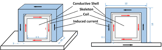
The structure schematic of the developed rectangular vertical probe.
During the testing of the developed rectangular vertical probe, the eddy current is induced not only in the test plate but also in the conductive shell when an exciting current flow though the coil. The test plate under the coil and the conductive shell can form a completed loop for the induced current. The high conductivity completed current loop will improve the coupling degree between the rectangular vertical coil and the test plate and enhance the eddy current under the coil. We can deduce that the change of the induced current, induced disturbed magnetic field and equivalent impedance will be more distinct with the proposed probe when defect exists in the plate. Then the sensitivity of the detective probe is improved.
The ECT is a complex electromagnetic problem as the eddy current in the test plate varies with the location and the time. The impedance of the induced loop and the coupling coefficient between the two loops are difficult to formulate especially with the presence of the defect.
In order to verify the performance, a 3D finite element model of the developed probe is set up using COMSOL Multiphysics. The model consists of the rectangular vertical coil, the conductive shell, the test plate and the air. The detective coil is wound on a cubic skeleton by the enameled copper wire with a diameter of 0.15 mm. The skeleton is with the size of 6.6 mm × 6.6 mm × 9 mm. The coil has 4 layers and 60 turns on each layer. The conductive shell encircles the detective coil along the direction of the windings. The shell uncorks towards the test plate. The height and the length of the shell are both 10 mm, and the width and thickness are 12 mm and 2 mm, respectively. The structure parameters of the developed probe are labeled in Fig. 2. Pure copper is chosen as the material of the shell. An 80 mm × 80 mm × 5 mm plate with a rectangular slot in the center is placed below the probe as the test plate. The material of the test plate is aluminum alloy 6063. The origin of the coordinates is set at the center point of the upper surface of the test plate. The air region is 150 mm × 150 mm × 150 mm.
The free tetrahedral mesher with predefined sets of finer is employed to generate the mesh of the 3D model. As the induced current mainly concentrates on the surface of the shell and the plate, we subdivide meshes in these parts in order to improve the accuracy of simulation. We divided the skin layer of the shell and the plate into hexahedron grids, and ensured that there were 3 to 5 grids within 0.3 mm. The hexahedral grids and tetrahedral grids can be compatible with each other with the transformation interface. The meshing of the model is shown in Fig. 3.

The simulation model of the ECT with the designed probe.
We use frequency domain solver to carry out this simulation. The iterative solver GMERS (generalized minimal residual method) is employed to increase the accuracy of the simulation. The exciting current is introduced to the coil by an AC current source of 0.1 A. Then the distribution of magnetic field and eddy current in different frequencies can be calculated by finite element method based on the Maxwell’s equations as following.
It took about half an hour to complete the simulation at each frequency, and the relative tolerance can be limited to 0.1% after five iterations.
Distribution of the induced current
To check the effect of the conductive shell on the detection, the distributions of the eddy current in the test plate without defect are studied and present first. Without the defect, the eddy current density distributions of the conventional and developed rectangular vertical probe at 100 kHz are shown in Fig. 4.

The eddy current density distributions without the presence of defect at 100 kHz.
In the figure, (a) and (b) is the side views of the eddy current distribution with conventional probe and developed probe, respectively. It could be seen that the induced current in the test plate is mainly concentrated in the area under the coil. And current density attenuates with the depth. The maximum density of the developed probe is much higher than the conventional probe owing to the completed current loop consisted of the shell and the plate under the probe. The eddy current density in the center axis is depicted in the Fig. 5. The current decreases exponentially with depth. The surface eddy current density of the developed probe is about 9.15 × 10⁶ A m−2, while that of the conventional probe is about 3.89 × 10⁶ A m−2.

The variation of the eddy current density along the axis (x = 0, y = 0) at 100 kHz.
Figure 4(c) and (d) show the top view of the eddy current density distribution. From the figures, it can be found that the area in the plate that is not under the probe has a non-negligible current as the current under the probe forms a loop with the other area in the plate during the testing with the conventional probe. However, there is nearly no eddy current in the other area of the plate during the testing with the developed probe. We depicted the variations of the surface eddy current density of the plate in the Fig. 6(a) and (b) along x and y axis. As shown in the figures, the eddy current in the area under the probe with the developed probe shows a more concentrated and uniform distribution compared to the conventional probe. An obvious higher density under the probe is observed. The analysis verifies that the shell of the developed probe can participate in the circuit loop of the induced current and improve the coupling between the probe and the test plate.

The variation of the eddy current density in the surface of the plate at 100 kHz.
As the analysis in Section 2, the distribution and density of the eddy current changes with the presence of the defect. In our simulation, a rectangular slot perpendicular to the coil windings with the size of 1 mm × 1 mm × 6 mm is employed. The distributions of the eddy current with the conventional and developed probes are shown in Fig. 7. From the side and top views, we can find that the eddy current in the plate flow to the two ends and the bottom of the defect to bypass the defect. For the conventional probe, the eddy current under the coil forms the closed current loop with the eddy current in the other area of the plate as shown in Fig. 7(c). For the developed probe, the eddy current under the coil mainly forms the closed current loop with the conductive shell as shown in Fig. 7(b) and (d). Compared to the conventional probe, the eddy current induced by the developed probe is more concentrated in the area under the coil and with a much higher density especially in edge of the defect. Then more obvious changes of the disturbed magnetic field intensity and equivalent reactance could be produced and observed.

Distribution of the eddy current at presence of slot.
The surface magnetic flux density of the plate under the coil is usually an indicator of the defect in the testing with the rectangular vertical probe. As shown in Fig. 7, the eddy current in the plate flow to the two ends and the bottom of the defect to bypass the defect. The current density at the ends of the slot is higher than elsewhere as depicted in the top view (Fig. 7(c) and Fig. 7(d)). Consequently, the z component of the surface magnetic flux density (B z ) is produced by the disturbed eddy current and the maximum values will appear near the defect ends which is parallel to the direction of eddy current. However, the rotational direction of the eddy current are opposite at two ends of the defect. So B z at two ends of defect are also in opposite directions. On the other hand, the y component of the surface magnetic flux density (B y ) responds to changes of the surface eddy current density. When a defect exists, B y will be reduced as the density of surface eddy current decreases. And the reduction will increase when the defect depth increases. So B y is related to the depth of the defect. In the detection, the properties of a defect can be evaluated by the inspections of B y and B z .
In this section, the performance of the proposed probe is studied by the disturbed magnetic field intensity in contrast to the conventional probe. And the influence of the defect characteristics on the disturbed magnetic field is also contrastively analyzed.
Defect of defect edge
As mentioned above, the maximum of B z appears at the defect edges which are parallel to the direction of eddy current. Herein, only the detection of defect length is simulated and analyzed while the detection of defect width is similar but with a changed direction of the probe. In this part, the width and depth of the defect are both set to 1 mm. The z component of the disturbed magnetic field intensity above the plate (along the axis of x = 0, z = 0.1 mm) with the defect of different lengths is depicted in Fig. 8.

The variation of B z along the axis of (x = 0, z = 0.1 mm) with different defect lengths at 100 kHz.
As shown in the figure, B z reaches the peak at each end of the defect. The information of the defect length can be acquired by the peak points of B z . On the other hand, the peak value of B z will be influenced by the length of the defect. With the decreasing of the lengths, the eddy current impeded by the defect decreases, and the current density at the ends of the defect decreases slightly. From the figure, we also can find that the peak values of B z in the detection with the developed probe is more than twice as those with the conventional one. The improvement is mainly due to the increase of the eddy current density mentioned above. When the defect is small, the bent of the eddy current and the change of the z component of the surface magnetic flux density are both tiny. The disturbed magnetic field will be hard to detective. The developed probe can effectively enlarge the change and the disturbed magnetic field, then improve the sensitivity of the detection.
In this part, the length and width of the defect are set to 6 mm and 1 mm. The y and z component of the disturbed magnetic field intensity above the plate (along the axis of x = 0, z = 0.1 mm) with the defect of different depths are depicted in Fig. 9.

The variation of the disturbed magnetic flux density along the axis of (x = 0, z = 0.1 mm) with different defect depths at 100 kHz.
The variation of B y is shown in Fig. 9(a). From the figure, B y in the center of the defect decreases when the defect depth increases. With the proposed probe, B y has a much larger value than those with the conventional probe, and its reduction due to the defect of different depths are more obvious. The variation of B z is described in Fig. 9(b). It shows that the peak value of B z increases with the defect depth increases. This is because eddy current will be more concentrated at the defect ends rather than the defect bottom when the defect depth increases. And it also can be found that the peak value of B z with the developed probe is more than twice as that with the conventional probe when the defect depth is the same.
We depict the variation of B y in the center of the defect and the peak value of B z with defect depth in Fig. 10. The comparison between the developed and conventional rectangular vertical probe indicates that the developed probe can increase the disturbed magnetic flux density and improve the sensitivity of the defect depth detection.

The variation of magnetic flux density with defect depth.
With the present of the defect, the coupling between the exciting coil and the induced loop will be reduced, and the equivalent reactance of the probe will be larger than that at the absence of the defect. The change of the equivalent reactance is another indicator for the evaluation of the defect. Herein, the simulated result of the reactance changes with the conventional and developed probe is comparative analyzed. We changed the frequencies of the exciting current from 10 kHz to 100 kHz. The changes of reactance with two different probes are shown in Fig. 11. In the figure, the change of reactance ΔX refers to the difference between the equivalent reactance of the probe on the defect plate and that on the defect-free plate. From the figure, it can be found that the changes of reactance with the developed probe is more distinct. And the changes are more than four times as that with the conventional probe at each frequency. This result also depict that the developed shell can improve the performance of the rectangular vertical probe.

The changes of the equivalent reactances due to the defect with different probe at different frequency.
To validate the improved performance of the proposed probe, a reactance measurement is conduct in this study. In the experiment, the structure parameters of the probe are almost the same with the simulation. However, the layer of the coil is subject to the winding technology and reduced to 3. The photograph of the proposed probe is shown in Fig. 12. As shown in the figure, the detective coil is wound on an ABS skeleton produced by a 3D printer (Prusa Mendel I3). And the windings is under the copper shell and cannot be seen in the figure. The rectangular slot employed here is with the size of 2 mm × 2 mm × 50 mm. During the testing, the probe is place in the middle of the slot and the direction of the windings is perpendicular to the slot.

The photography of the proposed probe.
The equivalent reactance of the probe is measured with Precision Impedance Analyzer Wayne Kerr 6500B from 50 kHz to 100 kHz. And a simulation with the same arrangement of the experiment is conduct for comparison. The change of the reactance is defined in the Section 4.3. The results are shown in Fig. 13. From the figure, the experimental results agree with simulation results in the measurement with the conventional rectangular vertical probe. For the proposed probe, the experimental reactance at each frequency is a little lower than the simulation one. This deviation may be caused by the structural differences such as different gaps between the windings and the shell. However, the experimental results still show that the reactance changes of the proposed probe due to the defect is about four times than those of the conventional probe. The results verify that proposed probe can effectively improve the detection capability of the rectangular vertical probe.

The experimental results of the change of the equivalent reactance.
A novel shelled rectangular vertical probe for the ECT of plate is proposed in this study. The developed probe consists of a conventional rectangular coil and an open-ended shell with high conductivity. It has a simple construction and is easy to implement with a conventional rectangular coil. During the testing of the developed probe, the shell and the test plate form a completed loop for the flow of the induced current, and effectively enhance the coupling between the vertical coil and test plate. The performance of the developed probe is studied numerically with the finite element simulation. The increases of the eddy current density in the test plate under the coil are verified. More obvious changes in the induced magnetic flux density and equivalent reactance can be derived in the simulation. And the experiment of reactance measurement is also conducted to verify the improved performance of the proposed probe. The results validate that the developed probe can improve sensitivity of the defect detection in the plate testing effectively.
Footnotes
Acknowledgements
This work is supported by the National Natural Science Foundation of China (51607152) and the Presidential Fund of the Xiamen University (20720180079).