
Abstract
The purpose of this paper is to optimize the PM arc ratio of consequent pole permanent magnet vernier machine (CP_PMVM). The operation principle of the CP_PMVM is discussed. An optimization parameter K 𝛼 related to the PM arc ratio is derived. For the CP_PMVM, the amplitudes of the 4th and 14th order harmonics of the air-gap flux density, the amplitude of the back electromotive force (back-EMF) and the average torque all have positive correlations with K 𝛼. The optimal PM arc ratio is 0.64. The three phase inductances are approximately constants, and the d-axis inductance is equal to the q-axis inductance. The PM flux linkages are sinusoidal. The no-load back-EMF waveform of the measured phase is nearly sinusoidal. The gear ratio of the CP_PMVM evaluated from the back-EMF is close to the design value. Furthermore, a controller according to the mathematical model is designed. The CP_PMVM vector control with a sliding-mode (SM) speed controller exhibits a smooth starting, and has an anti-jamming capability.
Keywords
Introduction
Investigating direct-drive machines is an effective method for improving the efficiency and simplifying the system structure. In recent years, the research on permanent magnet vernier machines (PMVMs) has become one of the hot spots. Due to the magnetic-gearing effect, the low-speed high-torque PMVMs are suitable for direct-drive applications, such as robotics [1] and electric vehicles [2], etc.
The classical rotor configuration of PMVM is that the permanent magnets (PMs) are surface mounted on the rotor-yoke with alternate N- and S-poles. While, a PMVM with high gear ratio needs a large number of PMs. Chung et al. [3] proposed a consequent pole PMVM (CP_PMVM) with less PMs. Half of PM poles are replaced with iron poles. Reasonable design of consequent pole (CP) rotor can decrease the leakage flux, increase the reluctance torque, and improve the torque density [4]. Moreover, the PMs are embedded in the rotor yoke. This CP structure can greatly increase the mechanical strength of rotor. In CP machine design, the PM arc ratio is an important parameter. Kwon et al. [5] optimized the PM arc ratio by finite element analysis (FEA). Bai et al. [6] gave a relationship between the fundamental air-gap flux densities above the PM- and iron-poles. Li et al. [7] optimized the PM arc ratio of the CP permanent magnet synchronous motor (PMSM). To further improve the theory of machines with CP rotors, this paper optimizes PM arc ratio from magnetic motive force (MMF) aspect based on equivalent magnet circuit, and extends the theory to CP_PMVM.
Moreover, to realize the stable operation of PMVMs, several control strategies have been introduced, such as direct torque control (DTC) [8] and sensorless vector control [9], etc. In this paper, the controller based on sliding-mode (SM) vector-control method is designed, and the simulation results are analyzed.
The main works of this paper are:
i. For a PMVM, the air-gap magnetic field is modulated by stator split-teeth. The air-gap flux density can be calculated as [10]
ii. Unlike the conventional PMSM, the CP_PMVM is a self-decelerating machine. The winding inductances, the PM flux linkages, and the back-EMF are calculated. According to these characteristics, although the PM amount is reduced, the control methods for PMVM are suitable for the CP_PMVM. Hence, the gear ratio, the direction of rotor speed, and the direction of the rotating magnetic field produced by the armature windings are taken into consideration. The mathematical model of the CP_PMVM is established. Then, the vector-control method is used to control the CP_PMVM. To improve the robustness, a sliding mode (SM) speed controller is added to the system.
Operation principle
The derivation is based on the following assumptions:
i. The relative permeability (μFe) of the silicon steel lamination is infinite, i.e. the magnetic reluctances of rotor- and stator-yokes approximate to zero. The saturation effect of the silicon steel lamination is neglected.
ii. The end-effect and the magnetic flux leakage are ignored.
iii. The PMs are radially magnetized.
The equivalent magnetic circuit of the CP_PMVM is shown in Fig. 1(a). Before discussion, two parameters are defined.

Equivalent analytical model. (a) Equivalent magnet circuit of the machine with CP rotor, (b) Equivalent MMF waveform in air-gap.
(1) The PM arc ratio of the CP rotor is denfined as [11]
(2) As mentioned in [12], considering the variation of stator split-teeth, the air-gap MMF can be derived by using the equivalent air-gap length
The PM MMF in Fig. 1(a) is [14]
According to the equivalent magnetic circuit, the PM flux per pole can be expressed as
As shown in Fig. 1(b), the air-gap MMF can be equivalent to a square-wave due to (8). Taking the rotor rotating into consideration, the air-gap MMF can be calculated by using Fourier transform as
Due to the modulating effect of stator split-teeth, the air-gap permeance per unit area can be expressed as [15]
It can be observed from ((12)) that the air-gap flux density B g contains three main components. Their pole-pair numbers are p r , (Z m − p r ) and (Z m + p r ). The component with pole-pair number p r is the fundamental harmonic. Its angular velocity is ω r . The components with pole-pair numbers (Z m − p r ) and (Z m + p r ) are modulated harmonics. Their angular velocities are − p r ω r ∕(Z m − p r ) and p r ω r ∕(Z m + p r ), respectively. The EMF is proportional to the angular velocity [12]. The component with pole-pair number (Z m + p r ) is a low-speed harmonic [16], the EMF produced by it is not significant [17]. Here, this component is ignored.
The number of armature pole pairs should meet
The gear ratio can be given as
Hence, (12) can be simplified as
Substituting (10) (i = 1) into (15), the air-gap flux density can be rewritten as
For T
avg
in (20), only K
𝛼 is a function of 𝛼. To obtain the maximum torque, the PM arc ratio should meet [7]
The topology of the CP_PMVM is shown in Fig. 2. The stack length is 47 mm. The stator adopts 9 slots to accommodate concentrated 3-phase armature windings. The number of armature pole pairs is p c = 4. A stator tooth is split into two flux-modulating poles (split-teeth), and the number of stator split-teeth is Z m = 18. The PMs with the same magnetization direction are uniformly embedded in the rotor yoke to form PM-iron sequences. The number of PM pole-pairs is p r = 14. The PMs are NdFeB with B r = 1.1 T and μ r = 1.05. The rotor- and stator-yokes use silicon steel laminations. As marked in Fig. 2, the PM thickness h m is 3 mm, the air-gap length g is 0.8 mm, and the calculated carter coefficient k c is ∼1.17. According to (17), the relationship between K 𝛼 and 𝛼 is plotted in Fig. 3. It can be found that K 𝛼 reaches the maximum at 𝛼 = 0.64.

Topology of the CP_PMVM.

K 𝛼 versus 𝛼.
Two-dimensional (2D) finite element method (FEM) is employed to optimize the PM arc ratio. Figure 4 shows the no-load air-gap flux density of the CP_PMVM. The amplitude of the air-gap flux density is affected by 𝛼 (Fig. 4(a)). Figure 4(b) shows the space harmonic spectra of air-gap flux densities at 𝛼 = 0.5 and 0.6. The 4th and 14th order harmonics are useful. As emphasized in (15), they are corresponding to the components with pole pair numbers p c and p r , respectively. The amplitudes of the 4th and 14th order harmonics are changed by 𝛼. They achieve the maxima at 𝛼 = 0.64 (Fig. 4(c)) and 0.66 (Fig. 4(d)), respectively.

No-load air-gap flux densities under various PM arc ratios. (a) Radial component of the flux-density, (b) Space harmonic spectrum of (a), (c) Amplitude of the 4th order harmonic versus PM arc ratio, (d) Amplitude of the 14th order harmonic versus PM arc ratio.
From (18), it can be found that there is a positive correlation between the amplitude of the back-EMF and K 𝛼. As shown in Fig. 5, the amplitude of the back-EMF reaches the maximum at 𝛼 = 0.64. It can also be seen from (20), the varying trend of the average torque is consistent with K 𝛼. The CP_PMVM achieves the maximum output torque at 𝛼 = 0.64 (Fig. 6). The corresponding torque ripple is very low.

Amplitude of the back-EMF versus PM arc ratio.

Average torque on rotor versus PM arc ratio (Current density 2.65 A/mm2).
The above analysis shows that the optimal PM arc ratio predicted by the optimization parameter, K 𝛼, agrees with the FEM calculation. Hence, the optimal PM arc ratio K 𝛼 = 0.64 is selected.
Machine characteristics
Figure 7 shows the winding inductances of phase A. The self- and mutual-inductances exhibit slight fluctuations. The self-inductance is L AA ≈ 2.60 mH, and the mutual-inductances are M AB ≈ M AC ≈ −0.11 mH. Using the coordinate transformation, the d- and q-axis inductances are approximately equal, i.e. L d ≈ L q . Hence, the CP_PMVM can be regarded as a non-salient pole machine [18]. The PM flux linkages of three phases plotted in Fig. 8 are sinusoidal, which indicates that the CP_PMVM is suitable for AC current drive. In summary, the parameters of the CP_PMVM are listed in Table 1.

Inductances of phase A.

PM flux linkages of three phases.
Parameters of the CP_PMVM
Figure 9 shows the prototype of the CP_PMVM. The no-load back-EMF of the measured phase is plotted in Fig. 10. n 0 is the rotor speed. As shown in Fig. 10(a), the measured no-load back-EMFs under various rotor speeds are in agreement with simulation values, and the waveforms are nearly sinusoidal. The corresponding spectra of the measured back-EMFs are shown in Fig. 10(b), and the frequencies of back-EMF waveforms, f e , excited by rotor speed are listed in Table 2. n e = −60f e ∕p c is synchronous speed produced by armature windings. The ratio of n e to n 0 is the gear ratio of the CP_PMVM. The evaluated gear ratio is very close to the design value G r = −3.5. Figure 10(c) indicates that the amplitude of the fundamental back-EMF is nearly linear with rotor speed, and the slop of the fitting curve is k s ≈ 0.047 V∕rpm.

Prototype. (a) Stator, (b) CP rotor.

Back-EMF characteristics under various rotor speeds. (a) Back-EMFs of the measured phase, (b) Spectra of measured back-EMFs, (c) Amplitudes of fundamental back-EMFs.
Gear ratio evaluation under various rotor speeds
Mathematical model of the CP_PMVM
The control model of the CP_PMVM is established in d-q rotating reference frame. The d- and q-axis voltages can be expressed as [8,9]
Unlike the conventional PMSM, the kinematics equation of the CP_PMVM should consider the gear ratio, the direction of the rotor speed, and the direction of the synchronous speed produced by armature windings. It can be expressed as [19]
Assuming that the initial position of d-axis is aligned with the axis of phase A, the electrical angle and the electrical angular velocity of the rotating magnetic field produced by the armature windings are
The zero-d-axis current control strategy is adopted. Substituting (24) and (27) into (23), we can get
Ignoring the damping, i.e. D
a
= 0, (26) can be rewritten as
Here, the speed regulator is constructed by SM control. The state variables of the CP_PMVM system can be defined as
Here, the sliding mode surface is defined as [20]
The exponential reaching law is used to design the SM speed controller. The derivative of S can also be expressed as
According to (34), the SM speed controller is plotted in Fig. 11.

SM speed controller.
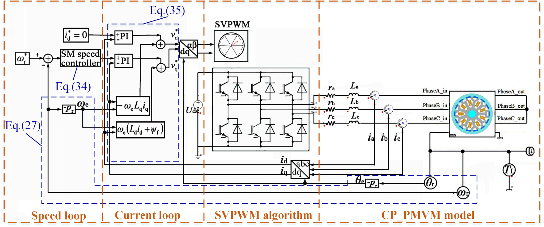
Configuration of the control system.
It can be found from ((23)) and ((24)) that there is a cross coupling between the d- and q-axis currents. Hence, the d- and q-axis reference voltages can be decoupled as [21]
According to the analysis above, the control model of the CP_PMVM is established in ANSYS Simplorer 19.0 software. As shown in Fig. 12, the control system contains a speed loop with the SM speed controller, a current loop with the PI current controller and a space-vector pulse width modulation (SVPWM) algorithm. The reference speed is 200 rpm. The control parameters are listed in Table 3. As a comparison, a PI speed controller is also introduced here. Figure 13 compares the simulation results of the SM and PI speed control modes.
Control parameters
Control parameters

Simulation results. (a) Speed tracking, (b) Torque variation, (c) Current of phase A.
During the no-load start-up stage, the SM speed control has no overshoot. The rise time of the SM speed control is little longer than that of the PI speed control. While the settling time of the SM speed control is shorter (Fig. 13(a)). The start-up current of the SM speed control is much lower (Fig. 13(c)), which results in lower starting torque (Fig. 13(b)).
A load torque of 4 Nm is applied to the CP rotor at 0.25 s. It can be observed from Fig. 13(a) that the SM speed control shows a faster speed response to disturbance. Generally, SM speed control can track the reference speed more accurately than PI speed control.
The PM-arc ratio optimization theory for CP_PMVM is presented. An optimization parameter K 𝛼 related with the PM arc ratio 𝛼 is derived from MMF aspect, and K 𝛼 reaches the maximum at 𝛼 = 0.64. The amplitudes of the 4th and 14th order harmonics of the air-gap flux density, the amplitude of the back-EMF and the average-torque all have positive correlations with K 𝛼. 𝛼 = 0.64 is selected as a final design. The phase inductances are nearly constants, and PM flux linkages are sinusoidal. A prototype of the device is manufactured and tested, the gear ratio calculated from the frequency of the sinusoidal back-EMF is close to the designed value −3.5. Moreover, the mathematical model of the CP_PMVM is analyzed. The controller based on SM vector-controlled method is designed. The simulation results indicates that the SM speed control can track the reference speed effectively, and has a good response to disturbance.
Footnotes
Acknowledgements
This work is supported in part by the National Natural Science Foundation of China under grant 51575236, and the Postgraduate Research & Practice Innovation Program of Jiangsu Province under grant KYCX18_1839.