
Abstract
The long-life driving coil is the prerequisite for electromagnetic forming industrial application. Up to date, the temperature rise is one of the major factors that restrain its working life. For the purpose of reducing the temperature rise of the driving coil, this paper proposes a new coupled cooling method, in which an extra cooling coil is placed on one side of the driving coil, then the Joule heating is coupledly transferred by delaying the breakover control of the driving coil. To achieve this purpose, a finite element simulation model of Electrical Circuit- Electromagnetic Field-Thermal Coupling in the plates setting of the electromagnetic forming is established, after which the influence rules of coil turns, cross-sectional area and materials of cooling coil on temperature rise are analyzed. Then, this paper also establishes a coupled cooling circuit model, in which the influence of cooling coil structure parameters on the Joule heating of driving coil is analyzed. Furthermore, Simulation results show that effective Joule heating transfer can be reached by the best optimization scheme of the cooling driving coil. Specifically, the average temperature rise reduces by 13 degrees, namely 22.8% by using this new method.
Introduction
With the development of advanced lightweight materials, the wide application of light alloys is urgently needed in the aerospace and the automobile industries. However, light alloy forming materials normally cannot get ideal forming effect by the traditional mechanical forming [1–3]. For instance, an aluminum alloy component used in aerospace engineering by the traditional mechanical forming requires using many times of deep drawing and multiple annealing to eliminate work hardening. These disadvantages of long production cycle and high cost restrict the industrial application of light alloys [4,5]. Therefore, it is urgent to find a new processing technology to solve the difficulty in light alloy processing, to expand the industrial application of light alloy, and to promote the development of energy saving and emission reduction in industries as aerospace, automobile, etc. [6,7]. Electromagnetic forming technology has attracted broad attention and is deeply studied due to its obvious advantages in the field of light alloy processing [8,9].
Electromagnetic forming (EMF) is a high-speed forming technology for metal material processing by using pulse electromagnetic force [10–12]. The equipment’s of EMF is simple, the cost is low, and the entire forming process can be finished within milliseconds. Since the forming speed is generally over 300 m/s, the high strain rate significantly improves the forming limit of metal materials [11]. Besides, the non-contact loading force also contributes to the high surface forming quality for metal materials [12]. However, in order to achieve an extensive application of EMF in industrial practice, it is necessary to improve the life performance of the driving coil in electromagnetic forming system.
It is easy to understand in the discharge process, the driving coil faces a harsh environment of high current, high voltage and high stress, which bring great challenges to its structural strength and insulation performance. Besides, insulation damage is another consequence of the temperature rise of the coil happened due to a sharp decline in electrical strength, which brings safety hazard to the continuous discharge of the driving coil. The existing studies show that the energy loss during coil discharge is released in the form of Joule heating, which is an important factor for low energy transfer efficiency in EMF [13]. For instance, Gies et al. found that the lost Joule heating accounts for approximately 49% of the total energy through experimental analysis. According to his research, the loss of Joule heating is gradually accumulated inside the driving coil; the internal temperature reaches nearly 178 °C; and the external temperature reaches close to 92 °C, which seriously damage interlayer insulation and decrease the coil life [14].
Therefore, how to reduce the temperature rise of the driving coil is the key to increasing the coil life. It is also the biggest challenge to realize EMF’s industrial application [15]. To solve this problem, Golovashchenko et al. proposed an air flow cooling method in EMF, in which the temperature rise is reduced from 150 k to 50 k per minute. It effectively reduces the temperature rise [16]. However, for the high-strength compact driving coil with internal reinforcement, the external air flow cooling method doesn’t function well. The only way that works is to reduce the thickness of the internal reinforcement layer of driving coil [17]. That is to say, the external physical cooling method has great limitation in reducing the temperature rise of the high-strength compact driving coil. To break the limitation, Cao et al. proposed an innovated discharge circuit configuration with a crowbar branch added to control the discharge current in the driving coil, which reduces the Joule heating without affecting the forming efficiency and deformation effect [18–20].
In order to obtain sufficient electromagnetic force for the workpiece, the mechanical strength of the driving coil has to be improved, and the high-strength compact structure of the driving coil will inevitably lead to poor heat conduction effect [21]. That is to say, the conventional heat conduction cooling method Obviously does not work well for the high-strength compact driving coil. Therefore, this paper proposes a coupled cooling method to reduce the temperature rise of the driving coil.
Basic principles and innovative methods
Figure 1 shows the basic principle of sheet electromagnetic forming. The charging system charges the capacitor, and the discharge of the capacitor generates a pulse high current in the driving coil. The pulse current induces eddy current in the metal sheet. The electromagnetic force between the pulse current and the induced eddy current drives the sheet to deform at high strain rate. The circuit of EMF system is a typical LRC circuit, which shows that the pulse current is a sinusoidal oscillation and its amplitude is exponentially damped. Generally, the acceleration forming process of the metal sheet usually be completed in the first current pulse wave [18]. Through the approximate analysis, there is no longer coupling between the driving coil and the metal sheet after the first current pulse wave. When ignoring the dynamic process of metal sheet, the basic circuit equation of electromagnetic forming can be described as:
This is a typical LRC circuit equation, in which
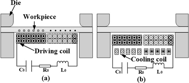
System of EMF. (a) Traditional loading; (b) Loading with coupled cooling method.
The pulse electromagnetic force provided by the driving coil for the sheet deformation is negligible after the first current pulse wave. However, the driving coil still generates and accumulates a large amount of Joule heating due to the remaining current pulse wave, resulting in increase of the temperature rise. In order to reduce the temperature rise of the driving coil, a closed cooling coil is introduced to be placed on the other side of the driving coil on the basis of the traditional sheet electromagnetic forming. Through the electromagnetic coupling between the cooling coil and the driving coil, the Joule heating of the driving coil is transferred to reduce its temperature rise, as is shown in Fig. 1(b). In the meantime, the cooling coil starts working after the first current pulse wave in order to avoid affecting the forming effect. At this time, the basic circuit and circuit equation of the electromagnetic forming with the cooling coil can be described as:
In the above figure and equation, M 2 is the coupling coefficient between the driving coil and the cooling coil. When t ≤ T 1, the driving coil is coupled with the metal sheet. When t > T 1, the driving coil is mainly coupled with the cooling coil to reduce the temperature rise of the driving coil.
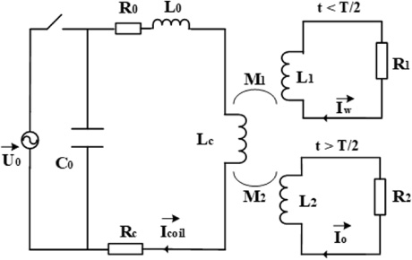
Equivalent circuit of EMF with coupled cooling method.
In order to explore the temperature rise of the driving coil caused by the cooling coil, an finite element model of Circuit-Electromagnetic-Thermal Coupling is established in the following illustration by using the COMSOL Multiphysics Software, which analyzes the effect of the temperature rise reduction of the driving coil. After that, a coupling equivalent circuit model is built using MATLAB Simulink Software. It then analyzes coupling heat transfer in the coupled cooling electromagnetic forming and the correlation between the resistance and inductance of the cooling coil.
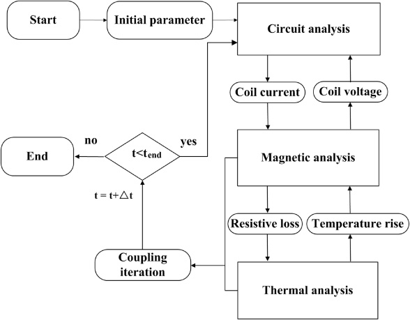
This section further analyzes the coupled heat transfer effect of the driving coil by establishing the Circuit-Electromagnetic-Thermal coupled model in EMF. Although EMF is mainly an electromagnetic-structural coupling process, this paper focuses on the temperature rise of the driving coil. Therefore, the following assumptions are made for metal sheet in the model: when the first current pulse wave remains unchanged, the conductivity of metal sheet is set to 0 to describe that it has already deformed far away from the driving coil, and there is no coupling relationship between them. Figure 3 is the flowchart of the implemented algorithm. Firstly, when initial parameters are assigned, the current of the driving coil may be reached through the solving of this circuit equation. Secondly, the pulse current flows into driving coil to generate a changing magnetic field. This change causes the coupling between the coil and the metal sheet, which then feeds back to the circuit for parameter updating. According to Joule’s law, the pulse current in driving coil generates a large amount of Joule heat, namely the temperature rise increases. It then leads to the change of the conductivity of the coil, which affects the whole coupling process in EMF. The timing of cooling coil is realized by setting the conductivity parameter as a piecewise function in the simulation. Finally, the model can be calculated continuously and updated until the end of the simulation.
Flowchart of the implemented algorithm.
The two-dimensional axisymmetric model is adopted to the model, and the electromagnetic field equation in the domain can be simplified as:
The driving coil adopts the natural heat convection, and its heat conduction equation is described as [6]:
Here, 𝜌 is the material density, C is the atmospheric heat capacity, k is the thermal conductivity, σ is the electrical conductivity, J is the current density, and Q is the electromagnetic heat source which refers to the Joule heating generated in EMF process.
The pulse current flows into the driving coil, which generates a large amount of Joule heating and leads to temperature rise. The coil temperature can be obtained from the following equation [21]:
Here, T
c
is the inside temperature of driving coil, m
c
is the coil mass, R
c
is the coil resistance,
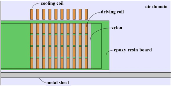
Schematic geometry of EMF with the cooling coil.
Based on COMSOL Multiphysics software, a two-dimensional axisymmetric model may be established, as is shown in Fig. 4. In this figure, the cooling coil, driving coil, and metal sheet are coaxially placed and closely aligned in the axial direction. The driving coil in this figure mainly consists of the copper conductor layers with cross-section of 1 × 4 mm2. The framework is made of epoxy resin board and the reinforcement layers the high-strength material - Zylon. The cooling coil is made of copper layers, and the metal sheet aluminum alloy AA5083 with a thickness of 2 mm and a radius of 50 mm. The main parameters of material are shown in Table 2.
Material parameters
Joule heating of driving coil
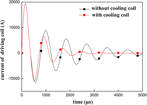
Waveforms of discharge currents in driving coil.
Figure 5 is a comparison diagram of the driving coil pulse current with and without cooling coil. In the first current pulse wave, the waveform of coil current is completely coincident, which indicates that the forming effect of the metal sheet is not affected by the introduction of the cooling coil. However, while the cooling coil is introduced, the current amplitude of the driving coil decreases significantly after the first current pulse wave. Also, the equivalent pulse width of the current decreases due to the mutual coupling of two coils. As a consequence, the Joule heating inside the driving coil is finally reduced.
In the electromagnetic forming process, the structure of the driving coil is usually unchangeable. So, the only way is to change the structural parameters of the cooling coil is to further analyze the influence of Joule heating and temperature rise of the driving coil, which usually includes turns, cross section and conductivity.
Turns of cooling coil
To explore the influence of temperature rise by changing the turns of cooling coil, so keep the cross section of cooling coil is 1 × 1 mm2, the conductivity is 6 × 10⁷ S/m, and the ambient temperature is set to 20 °C. Each layer of the cooling coil is 10 turns, and the number of the coil layers is gradually increased until the total coil turns is 4 × 10.
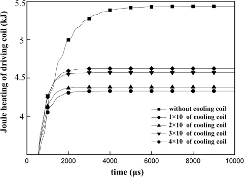
Joule heating of driving coil under different turns.
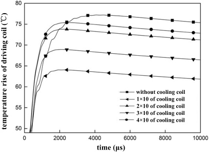
Average temperature rise of driving coil under different turns.
As is revealed in Fig. 6 and Fig. 7, the Joule heating of the driving coil without cooling coil reaches 5.44 kJ while introducing the cooling coil, the Joule heating of the driving coil is 4.33 kJ (when coil turns is 1 × 10), 4.38 kJ (when coil turns is 2 × 10), 4.57 kJ (when coil turns is 3 × 10) and 4.62 kJ (when coil turns is 4 × 10) respectively. Obviously, the Joule heating of the driving coil decreases significantly, as is shown in Table 2. However, with the increase of the coil turns, the Joule heating of the driving coil increases gradually, and the average temperature rise increases from 64 °C to 70 °C. In short, it is easy to find that the increase of the cooling coil turns makes it difficult to reduce the Joule heating and temperature rise.
In order to analyze the influence of temperature rise by changing cross sections of the cooling coil, five sets of simulation models of different cross sections are established. The wire cross-sections are 2 × 4 mm2, 2 × 2 mm2, 1 × 2 mm2, 1 × 1 mm2 respectively.
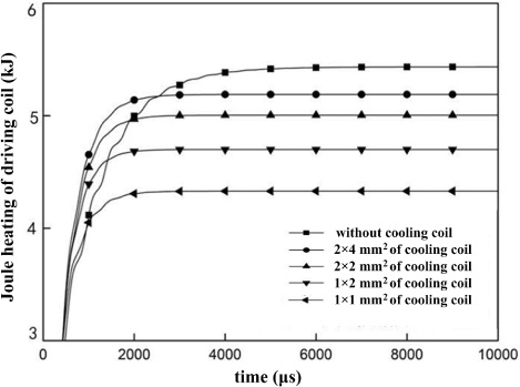
Joule heating of driving coil under different sections.

Average temperature rise of driving coil under different sections.
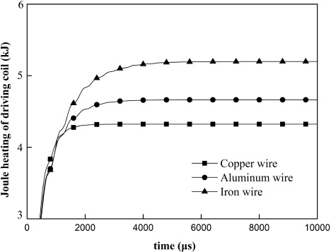
Joule heating of driving coil with different materials.
As is demonstrated in Fig. 8 and Fig. 9, when the cross section of the cooling coil gradually decreases, the total Joule heating of the driving coil gradually decreases and the temperature rise of the driving coil also decreases. Results are summarized in Table 3. Specifically, when the cooling coil is not involved in the coupled cooling, the Joule heating of the driving coil reaches 5.44 kJ. However, the Joule heating of the driving coil with 1 × 1 mm2 cooling coil is only 4.33 kJ, which decreases by 20.4%. In short, when comparing the corresponding value with and without the cooling coil, the average temperature rise reduces from 77 °C to 64 °C and the temperature drops by 22.8%. it is showed that both have the same tendency and a smaller cross section of the cooling coil is beneficial to reduce the Joule heating and temperature rise.
Joule heating of driving coil
It is known that wire materials usually contain copper, aluminum and iron. To analyze the Joule heating and temperature rise of the driving coil, this method changes the materials of the cooling coil. Three simulation models with different materials are established for comparative analysis of the Joule heating and temperature rise of the driving coil.
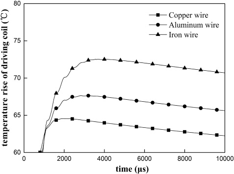
Average temperature rise of driving coil with different materials.
The Joule heating of driving coil.
Joule heating of driving coil
As is illustrated in Fig. 11 and Fig. 12, copper wire with the Best Conductivity has the best coupling heat transfer effect, and the temperature rise of the driving coil decreases mostly. Specific results are summarized in Table 4. When the material of the cooling coil is copper, the Joule heating of the driving coil is 4.33 kJ. When the material of the cooling coil is iron, the Joule heating of the driving coil rises to 5.02 kJ, and the temperature increases from 64 °C to 73 °C.
The above analysis suggests that when the cooling coil turns decreases, the resistance and inductance both decrease; when the cross-section of cooling coil decreases, the inductance undergoes a subtle change, but the resistance increases in multiples. At this point, there must be an optimal resistance value for the cooling coil, which makes the best effect of coupled heat transfer. In this case, when the turns of cooling coil is 1 × 10, the cross section is 1 × 1 mm2, it is the best scheme for coupled cooling coil to reduce the Joule heating and temperature rise of the driving coil.
It is demonstrated to be effective in reducing the Joule heating of the driving coil in the above illustration by introducing the cooling coil. As to the influence of coil structure parameters on the coupling effect, it is yet to be further analyzed, relevant coupled equivalent circuit is shown in Fig. 2. This paper focuses mainly on the cooling effect of the coupling of the driving coil, so it only analyzes the process of t > T in details. According to the coil coupling theory, the equivalent circuit is built by MATLAB Simulink software for simulation analysis. The basic circuit parameters are shown in Table 5.
Discharging parameters
Discharging parameters
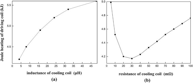
The coupling energy transfer of two coils is extremely complex, and the coupling coefficient is involved with many factors. In this section, we firstly set the driving coil structure parameters some certain value, the coupling coefficient of the two coils remain unchanged, we then change the inductance and resistance of the cooling coil separately to analyze coupled heat transfer effect. When R 2 = 20 mΩ, the coupling coefficient k = 0.6, we then adjust inductance of the cooling coil within the range of 4–50 μF. The effect of the inductance on the Joule heating of the driving coil is shown in Fig. 12(a). It is found that as the inductance of the cooling coil increases, the Joule heating of driving coil also increases, but the rate of increase gradually decreases. When L 2 = 4 μF, the coupling coefficient k = 0.6, we then adjust resistance of the cooling coil within the range 5–100 mΩ. The effect of the inductance on the Joule heating of the driving coil is shown as Fig. 12(b). It is suggested in the figure that with the increase of the cooling coil resistance, the Joule heating of driving coil increases after an initial decrease. When R 2 = 30 mΩ, the Joule heating of the driving coil is minimal. These results of simulation analysis are consistent with finite element analysis above.
It is tested in the above illustration and analysis that the method of coupled cooling can effectively reduce the Joule heating and temperature rise of the driving coil without affecting the forming efficiency. To be specific, this paper firstly demonstrates that selection of the proper resistance and inductance of the cooling coil can promote the transfer of the Joule heating from the driving coil changing the structure parameters of the cooling coil. Another conclusion may be drawn through detailed coupling analysis suggests that selecting metal materials with good conductivity, downsizing the cross section of cooling coil and coil turns contribute to the reduction of useless Joule heating. It is also illustrated that under the optimization scheme, about 23% of Joule heating is indirectly taken away, and the average temperature decreases by 13 °C, thus the effect of Coupled cooling is improved remarkably. However, the cooling effect on driving coil is far from reaching the standard of industrial application. Therefore, the mechanism of energy transfer still needs to be further studied on the basis of the Coupled heat transfer theories to obtain the optimal cooling effect for future study.
Footnotes
Acknowledgements
This work was supported by the National Natural Science Foundation of China (51607152, 51877122) and Sponsored by Research Fund for Excellent Dissertation of China Three Gorges University (2019SSPY070, 2019SSPY065).