
Abstract
A novel three-degree-of-freedom (3-DOF) spherical motor based on the principle of minimum magnetic reluctance is proposed in this paper. This paper firstly introduces the structure of the reluctance spherical motor and explains the principle of 3-DOF motion of the motor in detail. Then, an analytical model for reversible torque-angle characteristics is established to accurately describe a complex nonlinear system of the spherical motor model by using piecewise function nonlinear fitting method. Finally, the simulation results of torque-angle characteristics based on the nonlinear model are compared with those of the 3D finite element method (FEM), which verifies the feasibility of the nonlinear modeling.
Introduction
Spherical motor is a new type of multi-degree-of-freedom (DOF) actuator, which can realize multi-dimensional motion in space. Compared with the traditional multi-DOF drive system composed of multiple one-DOF motor, spherical motors have many advantages in structure and performance. Therefore, various types of spherical motors have been developed and studied extensively [1–8].
Permanent magnet (PM) is often introduced into the structure of the multi-DOF spherical motors, which can improve its operation efficiency. However, the introduction of PM into three-dimensional spherical structures makes the magnetic field distribution complicated [9–11], meanwhile result in strong nonlinearity and coupling for spherical motors and difficulty in motor control [12–14]. Therefore, a novel three DOF spherical motor based on the principle of minimum reluctance is proposed [15], which means that the magnetic flux always closes along the path with the smallest reluctance. The motions of the proposed 3-DOF spherical motor are like a stepping motor that uses reluctance torque. Moreover, the reluctance spherical motor has no any PM and only the stator windings are excited, which is more cost-effective [16]. Both stator and rotor are of laminated structures, thus the cost, volume, and weight can be reduced and the manufacturing efficacy can be improved [17].
For a 3-DOF spherical motor, it is important to control the position and torque of the motor. The exact characteristic of the spherical motor is normally analyzed by 3D FEM, but the simulation time of FEM is excessively long and requires excessive calculation memory [6,18]. On contrary, the traditional equivalent magnetic circuit method cannot precisely analyze the spherical motor as it does not consider the nonlinear characteristics of the motor [10,19]. In order to quickly obtain the torque, a piecewise function nonlinear fitting method from [20] is used to establish the analytical model of the torque-angle characteristics. The analysis results of the nonlinear model are compared with those of the FEM analysis to verify its accuracy. Furthermore, the FEM simulation results of the torque characteristics show the feasibility of the proposed spherical motor.
Overall structure of proposed spherical motor.
Structure of the spherical motor
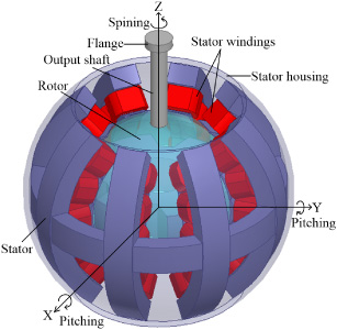
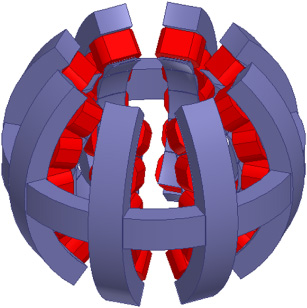
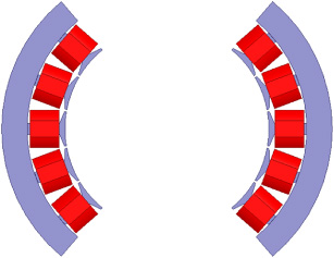
Figure 1 shows the basic structure of the 3-DOF reluctance spherical motor proposed in this paper. The rotor and stator structures of the spherical motor are respectively shown in Fig. 2 and Fig. 3. Both the rotor and the stator are designed as salient poles with a laminated structure for manufacturing convenience. Moreover, the proposed motor is a single excited type, in which only the stator has winding coils. The rotor has no coils as shown in Fig. 2, it has 6 poles evenly distributed in the circumferential direction and each pole has one tooth. Figure 3 shows the basic stator structure of the spherical motor. For ease of understanding, we divide the stator core into two parts. One is the core along the equator of the sphere used for spinning motion, which is called spinning stator as shown in Fig. 4. The other is a stator core used for pitching motion and called a pitching stator. And an example of one pole is shown in Fig. 5. The spinning stator is the same as the stator of four-phase switched reluctance motor, it has four phases and a total of 8 teeth evenly distributed along the equator of the sphere. The pitching stator consists of 8 same cores at 45° intervals along the circumference, totally forming four poles, and there are 5 teeth distributed at equal latitude intervals of 19° on each core. Two diagonally located coils of each pole compose one phase, making up a total of five phases. Besides, each pole tooth of the stator is wound with a basic winding coil.

Rotor structure of proposed spherical motor.
Stator structure of proposed spherical motor.
In addition, the end of the motor output shaft is equipped with a flange for transmitting and outputting the torque of the 3-DOF spherical motor. Table 1 shows the basic specification of the reluctance spherical motor.
The proposed spherical motor can complete 3-DOF movements that include spinning motion and pitching motion. The operating principle is basically similar to that of switched reluctance motor. It follows that the magnetic flux always closes along the path with the smallest reluctance, and the magnetic pull force is generated to form the torque.

Spinning stator.
Pitching stator.
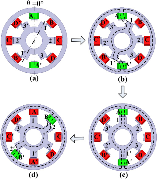
Figure 6 demonstrates the principle of the spinning motion of the proposed spherical motor. As shown in Fig. 6(a), when the magnetic pole axis of phase A of the spinning stator coincides with the neutral line between the rotor poles, spin angle θ at this position is defined as 0°. When the pole axis of phase A does not coincide with the rotor pole axis as shown in Fig. 6(b), only phase A winding is excited. Then, the magnetic lines (indicated by the dotted line in the figure) passing through the air gap are curved, and the magnetic resistance of the magnetic circuit at this time is not the smallest, which will produce reluctance torque to turn the rotor in the direction where the length of the magnetic flux shortens. When the rotor rotates for 15°, the rotor reaches a stable equilibrium position when the stator pole A and rotor pole 1 align, as shown in Fig. 6(c). At this time, phase A is powered off and the phase B is excited as shown in Fig. 6(d), the rotor rotates in a step. Moreover, the four phases of the stator winding are energized in the order of A-B-C-D, the rotor can spin 60° counter-clockwise. A complete spinning motion contains 24 steps, which performs a 360° rotation.
The basic specification of proposed reluctance spherical motor
Principle of the spinning motion.
The operating principle of the pitching motion of the proposed spherical motor is shown in Fig. 7. First, when the rotor magnetic pole is aligned with stator phase c, the pitch angle φ = 0° is defined at this position as shown in Fig. 7(b). And the counterclockwise motion of the rotor is defined to be positive. In Fig. 7(a), when the rotor pole is aligned with stator phase b, pitch angle φ is −19° at this position because the 5 teeth are equally distributed at a latitude of 19°. After phase c is excited, the unbalanced flux path is established as shown in Fig. 7(a). Then, the rotor moves due to the torque generated by the tangential magnetic pull force of the bending magnetic lines, which forces the rotor and stator teethes to be aligned for minimum reluctance. When the rotor pitches by 19°, φ is 0° where the magnetic reluctance torque becomes a minimum. Then, as shown in Fig. 7(c), if phase c is unexcited and phase d is excited, the rotor starts the next same stepping motion and finally pitches to the position as shown in Fig. 7(d). Due to the structural limitations of the motor, four step movements are required to complete a full pitching motion clockwise, and the rotor can pitch by ±38° at 19° intervals. Figure 7 corresponds to the two clockwise steps from pitch angle φ = −19° to φ = 19°. Besides, the rotor will continuously perform pitched stepping when the pitching stator phases are excited in the order of b-c-d-e-d-c-b-a-b.

Principle of the pitching motion.
Therefore, the motion of the proposed spherical motor is a stepping motion according to the change of the excitation phase, and operating principles at each step are identical. Moreover, the rotor moves in accordance with the same principle of reducing the reluctance considering the excited phases.
The structure and working principle of the reluctance spherical motor proposed in this paper are not very complicated, but the nonlinearity of the magnetic circuit and the periodic excitation make the physical quantity of the motor change periodically with the rotor position. The internal magnetic circuit waveform of the motor is extremely irregular, and the local magnetic circuit at the top of the salient pole is severely saturated.
In order to precisely analyze the spherical motor, the core saturation, leakage flux and fringing effects are required to be considered. Traditional motor analysis methods such as magnetic circuit method are difficult to carry out this kind of analysis, and FEM was mainly used normally. However, FEM has the disadvantage of long simulation time [6]. In this paper, based on a nonlinear fitting modeling method of the switched reluctance motor proposed in [20], the nonlinear modeling of the spherical motor is established and the analytical parameters in the model are further optimized, and then the model is analyzed and validated.
Theoretical analysis
Since the spinning motion and the pitching motion are essentially similar, only the analysis of spinning motion is described. The spinning model shown in Fig. 6 can be considered as a four-phase switched reluctance motor with 8/6 poles. Assuming that the parameters are symmetrical, according to the circuit law, the electromotive force equation can be written as
The virtual work method is used to calculate the torque. It is assumed that the flux linkage keeps constant and the loss is negligible. According to the law of conservation of energy, the input power increment of the system ΔW
e
is equal to the sum of the magnetic field energy storage increment ΔW
f
and the mechanical energy change ΔW
m
. When ΔW
e
equal 0, ΔW
m
. is obtained as
When the magnetic field of the spinning model of the spherical motor is saturated, the output torque varies linearly with the current [21]; If the magnetic field is not saturated, magnetic circuit is linear, the phase inductance L(i, θ) is independent on the current i and only depends on θ. Therefore, when the magnetic field is not saturated, T
e
(i, θ) can be written as
According to mechanics principle, the torque balance equation on the output axis of the spherical motor can be expressed as
The 3-DOF motion of the spherical motor can be decomposed into the spinning motion and the pitching motion. The output torque of the motor can also be decomposed into the corresponding spinning torque and pitching torque. Thus, the nonlinear modeling of the spherical motor can be divided into the spinning model and the pitching model. As the working principles of the spinning motion and the pitching motion are the same essentially, only the nonlinear modeling of spinning is analyzed and described in this paper.
When the magnetic field of the spinning model of the spherical motor is not saturated, the phase inductance L (i, θ) is recorded as L (θ) and note that the derivative of the spinning inductance L (θ) to angle θ is L
p
(θ), according to (5), T
e
(i, θ) can be written as
However, the reluctance spherical motor proposed in this paper works in the state of magnetic field saturation. As mentioned above, the output torque is no longer proportional to the square of the current value, but varies linearly with the current. In order to ensure the effectiveness in saturated region, the parameters of the new torque model must meet two requirements. First, when the current is small, the new torque formula should be equivalent to (7), that means the torque is proportional to the square of the current; Second, when the current increases gradually and the motor becomes saturated, the new torque equation will gradually change from the quadratic function of the current to the linear function. Particularly, when i →∞, i.e. the torque equation is reduced from the quadratic function of the current to a linear function, it is recorded as
Here the current value i = 1∕f 1∕n is the boundary point between the linear relationship of the torque and the current and the quadratic relationship. Furthermore, according to [20], the value of n affects the ratio of maximum to minimum equivalent self-inductance of phase windings. Due to material and structure constraints, parameter n equals 3 is the best choice for most practical switch reluctance motors [21]. Obviously, when the current i is much less than 1∕f 1∕n , (9) is equivalent to (7). In addition, (9) is reversible, the current can be derived from the torque when the torque is known.
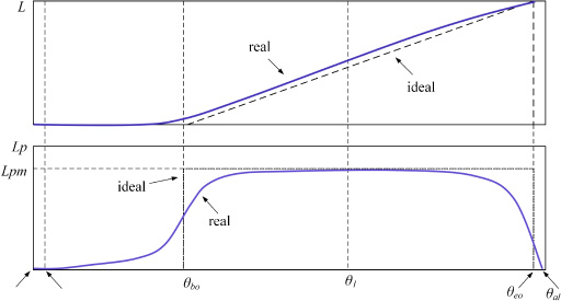
As the spinning model of the reluctance spherical motor is like that of switched reluctance motor, the ideal and real curves of the spinning phase inductance L (θ) and its derivative L p (θ) can be obtained according to [20], as shown in Fig. 8. Ideally, magnetic circuit is linear, the ideal curve of the inductor and its derivative are shown by dotted line in Fig. 8. When θ u ≤ θ≤ θ bo , the rotor pole is aligned with the spinning stator slot, the equivalent inductance of the air gap keeps the minimum, i.e. L (θ u ) = L min, and L p (θ u ) = 0; When θ bo ≤ θ≤ θ eo , the rotor pole moves from initially overlapping with the stator pole to completely overlapping, the inductance value increases linearly, and the derivative of the inductance to the angle is the constant L pm ; When θ eo ≤ θ ≤ θ al , the rotor pole moves from completely overlapping with the stator pole to where its axis coincides with the axis of the stator pole, the inductance value keeps its maximum value L (θ al ), and L p (θ al ) = 0. In fact, considering the effects of flux leakage and saturation, the real curves are shown by the solid line in Fig. 8. Besides, for most switched reluctance motors, θ1 shown in Fig. 8 is near the angle at which the rotor pole coincides with stator pole by 20%.
Ideal and real curves of L P and L P (θ).
The parameter L
pm
is the magnitude of L
P
and determines the peak value of L
p
and the spinning torque. In the case of ignoring magnetic flux leakage and ferromagnetic resistance, the value of L
pm
is only related to the geometric size of the motor [22], which can be estimated by
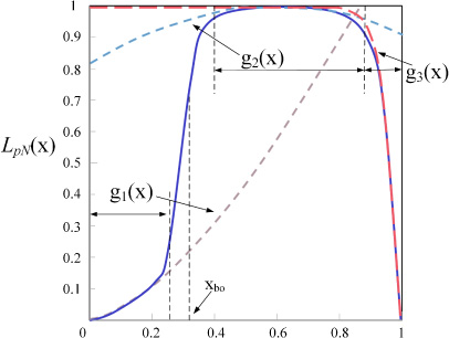
For convenience of description, x is defined as the normalized representation of the rotor angle, and x = (θ −θ u )∕(θ al −θ u ). Figure 9 shows the function representation of normalized L p , i.e. L pN (x) is the normalized representation of L p (x). In Fig. 9, x bo is the normalized spin angle when the rotor pole and the stator pole begin to overlap, which can be calculated by x bo = (θ bo −θ u )∕(θ al −θ u ); g 1(x), g 2(x), g 3(x) are three functions for each interval, g 1(x) mainly determines the shape of L p at interval 0 ≤ x ≤ x bo , g 2(x) mainly determines the shape of L p at interval x bo ≤ x ≤1, and g 3(x) is to ensure that the value of L p decays rapidly to 0 near the alignment position θ = θ al .
L P is fitted by g 1(x), g 2(x), g 3(x).
Then three piecewise functions are put into an analytical expression by using the fitting method, and the analytical expression L
p
of the whole interval is obtained. The fitting method is as follows
Since the spinning torque in the interval 0 < x < x
bo
is very smaller than those in the other intervals, we determine the function g
1(x) approximately as
For the spinning model of the proposed spherical motor, x
1 refers to the angle that the rotor pole rotates to cover 20% of the stator pole, that is x
1 = x
bo
+0.2(1 − x
bo
). When x = x
1, L
P
takes the maximum value, the function g
2(x = x
1) should be equal to 1. So, in the interval of x
bo
< x <1, according to [20], the following expression is proposed as
When the rotor pole is not aligned with and stator pole, the value of function g
3(x) is equal to 1; When the rotor pole is very close to align with the stator pole, that is x →1, the value of function g
3(x) should rapidly decay to 0. However, the widths of stator pole and rotor pole of the spherical motor proposed in this paper are significantly different, the attenuation amplitudes of g
3(x) are significantly different at the two positions where the stator pole and the rotor pole begin to completely overlap and close to the alignment. Thus, the expression of g
3(x) from [20] is given as
Considering the characteristics of the spinning model of the spherical motor, the magnetic field of the motor is unsaturated in the non-overlapping interval of the stator and rotor poles (i.e. θ
u
≤ θ < θ
bo
), especially the spin angle near θ = θ
u
, the nonlinear equation of electromagnetic torque (9) will become the linear equation (7), that means when θ → θ
u
, f → 0; On the other hand, the air gap saturation effect is most obvious at the positions x = x
bo
and x = x
eo
, which means that f (x) takes the maximum at these two positions. Therefore, f (x) can be expressed as
When x = x
eo
, the air gap flux linkage and current deviate from the linear relationship, the magnetic circuit is critically saturated, and ∂T∕∂i will reach the maximum value, namely:
When the magnetic circuit is critically saturated, the phase current value is marked as I
s
, the flux density is marked as B
s
, and the total air gap length is 2δ, which is obtained by the magnetic circuit balance equation ∫ Bdl = μ0 Ni:
For (15), f (x = x
eo
) ≈ c
2. Thus, from (15), (17) and (18):
When the magnetic circuit is deeply saturated, i.e. x = x
1, i → ∞, the electromagnetic torque can be calculated by (8), but the electromagnetic torque at deep saturation satisfies the following formula:
According to [20], in order to simplify the analysis, it can be considered that:
For (15), f (x = x
bo
) ≈ c
1. Thus, from (15), (21) and (22):
According to [20], x
1 ≈ (x
bo
+ x
eo
)∕2. So substituting x
1 into (15) gives:
Therefore, substituting (19), (21) and (23) into (24) gives:
In addition, as the values of B sat and B s are very close, unless particularly necessary, B sat = B s can be taken to simplify the analysis process.
The parameters of nonlinear analytical model of the proposed reluctance spherical motor in this paper can be reasonably adjusted within the allowable range. According to [20], for switched reluctance motors with definite dimensions, the model parameters x bo , x 1 and x eo characterizing the rotor angle are only related to the geometric shape of the motor, thereby they are fixed values in the analytical model. Therefore, for the proposed reluctance spherical motor whose dimensions have determined, the model parameters x bo , x 1 and x eo for the spinning model and the pitching model of the spherical motor are also fixed values, which can be calculated according to the normalized expression formula of the angle described above. As the material of the motor determines the curve shape of the derivative of the phase winding inductance L P (x), and then the shape of the torque curve. Therefore, when the material of the proposed reluctance spherical motor is determined, for different analytical models with different analytic parameters in a reasonable range, the values of the parameters μ1, μ2 and 𝛼, 𝛽 are the same. What’s more, the value of m affects the shape of the model curve in the interval 0 < x < x 1, while the value of h affects the shape of the model curve in the interval x 1 < x <1, especially near the alignment position x eo . According to (12), the appropriate values of the parameters μ1 and 𝛼 can be determined by comparing the curves of g 1(x) obtained by taking the different values of μ1 and 𝛼 within a reasonable range. The appropriate values of μ2 and 𝛽 can be obtained from (13) by using the same method. Similarly, the appropriate value of h can be obtained from (14). The value of m determines the smoothness of L P (x) near x = x bo , according to [20] and the position of x bo in the analytical model of the proposed reluctance spherical motor, it only needs to ensure that the value of m is sufficiently large. Therefore, the parameters x bo, x 1 and x eo can be obtained from theoretical considerations, other parameters including μ1, μ2, 𝛼, 𝛽, m and h can be determined by experiment and comparison, and the value of n is obtained by referring to relevant literature. In Reference [20], the values of relatively optimal analytical parameters are obtained by comparing the torque results of several analytical models with different combinations of these analytical parameters. Thus, based on the structure characteristics of the proposed reluctance spherical motor and referring to the relevant results of Reference [20], the value of each analytical parameter in the nonlinear analytical model of the spherical motor is determined as displayed in Table 2. Because the finite element analysis is more accurate, the torque results calculated by 3D FEM can be used as a reference to verify the accuracy the nonlinear analytical model of the spherical motor. Based on the basic specification shown in Table 1, the spinning and pitching finite element model of the reluctance spherical motor are established, and the 3D FEM results of the spinning and pitching static torque can be simulated.
Parameters of the nonlinear analytical model
As the exciting strategies of the spinning and pitching motion of the spherical motor are explained previously, when the stator windings are energized by 1600 ampere turns (i.e. DC ampere turns) from an ideal DC current source, the results obtained from 3D FEM and the nonlinear modeling analysis are shown in Fig. 10, Fig. 11, Fig. 12, Fig. 13 and Fig. 14. Furthermore, Fig. 10 only addresses the comparison of the spinning part of the spherical motor and the other figures show the comparison results of the pitching part.
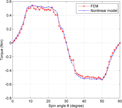
Comparison results of spinning torque-angle characteristics.
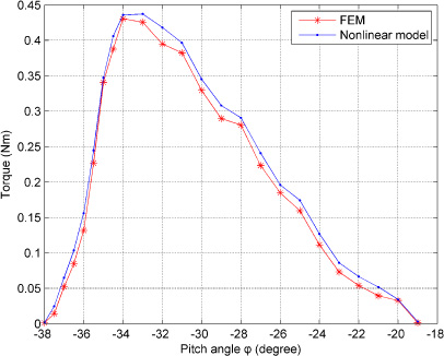
Comparison results of pitching torque when φ is from −38° to −19°.

Comparison results of pitching torque when φ is from −19° to 0°.

Comparison results of pitching torque when φ is from 0° to 19°.
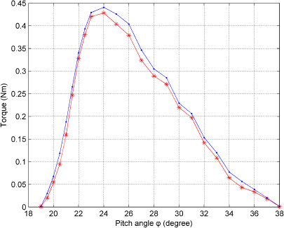
Comparison results of pitching torque when φ is from 19° to 38°.
Figure 10 presents the curve of the static spinning torque-angle characteristic when one phase is excited in an electrical period of the spinning motion in which θ changes 60 degrees. We can see that, the characteristic curve of the spinning torque-angle changes periodically with spin angle, which is basically identical to the switched reluctance motor. When spin angle θ rotates from 0° to 30°, the air gap decreases and the magnetic circuit becomes saturated gradually, when θ is small, the stator pole and rotor pole do not overlap, the air gap decreases slowly. whereas the air gap changes rapidly when θ is greater than θ bo , the magnetic circuit gradually changes from unsaturated state to saturated state and finally becomes seriously saturated. The spinning torque increases first and then maintains approximately constant when spin angle changes from about 9 degrees to 22 degrees, and then reaches to zero gradually. Moreover, the spinning torque approximately remains maximum that is about 0.54 Nm, meanwhile the average torque of the spinning motion is about 0.36 Nm. As shown in Fig. 10, the average of the differences of the spinning torques between the linear magnetic circuit and the FEM result is found to be about 3.56%, this indicates that the analytical calculation results are close to the finite element calculation results.
Figures 11, 12, 13, 14 show the comparison results of the pitching torque when the rotor pitches from −38° to −19°, −19° to 0°, 0° to 19° and 19° to 38° respectively. As explained previously, four stepping movements are required to complete a full pitching motion clockwise, thus the pitching torque-angle characteristic is analyzed at each step and are presented in these figures. This implies that the characteristic curves of the pitching torque-angle of the four steps are basically same. When pitch angle φ increases in each step, the magnetic circuit becomes saturated and the air gap decreases, the torque characteristic curves are also first increase and then decrease. However, compared with the spinning motion, the magnetic circuit between stator and rotor is shorter in the pitching motion of the spherical motor. As a result, the speed of magnetic circuit saturation is faster than that of the spinning motion in each step of the pitching motion, and the pitching torque accordingly reaches the maximum value correspondingly. Moreover, as the pole pitch of the pitching stator is smaller than that of the spinning stator and the magnetic circuit saturation effect, the characteristic curve of the pitching torque is not the same with the spinning torque curve, which is not basically symmetrical and the interval in which the maximum pitching torque is approximately constant is very short. The pitching torque is the maximum basically when rotor pitches four degrees from the initial position in each step and the maximum value of each step is about 0.45 Nm. And the average torque values of the pitching motion in four steps are basically equal and about 0.23 Nm. Further, the average relative error between the results of the nonlinear model and the results of FEM is about 4.36%, it shows that the nonlinear model is accurate. In addition, the pitching torque converges to 0 at the end of each step from the characteristic curves.
It can be seen that the calculation results of the nonlinear analytical model are very close to those of the FEM, which shows the validity of the nonlinear analytical model in this paper. Besides, we can find that the proposed 3-DOF motor can generate a holding torque in spinning and pitching motions, indicating the feasibility of the proposed spherical motor.
Footnotes
Acknowledgements
The research work of this paper is supported by the National Natural Science Foundation “Research on Key Basic Problems of complex motor systems” (51637001) and Anhui Provincial Natural Science Foundation Project “Structure Design and Optimization Research of a Multi-DOF Reluctance Spherical Motor” (1908085ME168).