
Abstract
In order to solve the contradiction between the opening and closing time of the high speed on/off valve for space propulsion systems of the liquid rocket engine, a pneumatic pilot-operated high speed on/off valve is proposed and multiobjective optimization for the opening and closing time of the valve is carried out in this paper. Based on the analysis of the working mechanism of the valve, the mathematical models for the pilot valve and the main valves are established respectively. The Plackett-Burman design is used to select the optimization variables which influence the performance of the response time significantly. The central composite design is used to obtain the sample points and establish second-order response surface models of the response time. The NSGA-II is used to obtain the Pareto front of the optimization objectives. The optimized opening and closing time can be reduced by 17.7% and 37.4% respectively. A prototype based on the optimized parameters is manufactured and tested to verify the accuracy of the multiobjective optimization results. The test results verify the validity of the optimization approach for the proposed valve in this paper.
Keywords
Introduction
The liquid rocket engine (LRE) plays an important role in a spacecraft. Its working state affects the performance and reliability of the spacecraft directly [1,2]. The fuel and oxidizer atomization performance determine the performance of the propulsion system. The propellant feed system used to transfer propellants with required pressure and flow rate from the tank to the combustion chamber, which affects the fuel and atomization significantly, and the high speed on/off valve (HSV) with the advantages of simple control, low throttling loss, no internal or external leakage, and strong anti-pollution ability is a key part of the propellant feed system [3]. Thus a HSV with the performance of high speed, high pressure, and large flow rate is vital for the propulsion system.
Based on the difference of electro-mechanical conversion device, the research of HSV mainly focuses on the electromagnetic direct-driven valve [4,5], the piezoelectric actuated valve [6] and the giant magnetostrictive valve [7–9]. In order to meet the requirements of large flow rate, the valve orifice area of the conventional direct-driven solenoid valve needs to be large, which results in a large fluid force acting on the valve core. If the electromagnetic direct-driven valve is adopted to control the on/off of the high-pressure fluid directly, the mechanism of the valve will become bulky and the response will be slow [10]. On the other hand, the electromagnetic direct-driven valve cannot be used to directly control flammable and explosive media for safety reasons. The piezoelectric actuated valve with the piezoelectric stack as a driving element has quick response and large driving force, but the stroke is too short to meet the requirements of a large flow rate even the displacement is amplified by the displacement magnifying device, and the piezoelectric stack is very expensive. So the application of the piezoelectric actuated valve is limited [11]. The performances of response time and flow rate of the giant magnetostrictive valves are better than the piezoelectric actuated valve. However, due to the inherent hysteresis characteristics of the giant magnetostrictive valve, the control accuracy is relatively low. If some improper control parameters are applied in some special circumstances, it may worsen output characteristics of the giant magnetostrictive valve [12]. To satisfy the requirements of high speed, high pressure and large flow rate, the pneumatic pilot-operated high speed on/off valve (PPHSV) with a direct-driven solenoid valve as the pilot valve and high-pressure gas as transmission medium has become the research and development trend of HSV [13–16].
As a two-stage HSV, the PPHSV can satisfy the performance of high pressure and large flow rate, but its response time is longer than the direct-driven solenoid valve. Therefore, how to improve the response performance of PPHSV is the current research hotspot [17–19]. According to the structure of PPHSV, two methods are used to improve its response performance. One is to optimize the response performance of the pilot valve based on the following four aspects: the structure innovation of solenoid valve [20,21], the application of new soft magnetic material [22,23], the improvement of driving circuit [24,25] and the optimization of control strategy [26–28]. The other is to optimize the response performance of the main valve, mainly focus on the structure parameters optimization of the control chamber [29]. The response performance of PPHSV depends on many physical fields involving electric field, magnetic field, mechanical field, and flow field, and the governing equations and interaction variables of these physical fields are mutually coupled [10]. So it is difficult to obtain the optimum response performance of the PPHSV by optimizing the pilot valve or main valve as a stand-alone system.
In view of the contradiction between the opening and closing time, the multiobjective optimization algorithms such as particle swarm algorithm [30], simulated annealing algorithm [31], multiobjective genetic algorithm [32] are used to improve the response performance of HSV. Due to the long calculation period of dynamic simulation for parameter optimization, the approximate model technology which can not only avoid tedious calculation but also fully consider the interaction between parameters is adopted to construct the functional relationship between the response time and the parameters of each physical field to optimize the design of the valve. The widely used approximate model includes response surface model [33,34], Krining model [35], etc.
In this paper, a PPHSV for the propulsion system of a spacecraft with bipropellant is proposed to meet the requirements of high speed, high pressure, and large flow rate. Aimed at improving the response performance of the valve, the mathematical models of the pilot valve and the main valve are established, and an optimization design method for the response time of the valve is proposed in this paper. Taking the opening and closing time as optimization objectives, the Plackett-Burman design (PBD) considering all parameters is carried out, and the parameters which have a more significant impact on the opening and closing time are selected as the optimization variables. Second-order response surface models (RSM) between the optimization variables and the response time are established through the central composite design (CCD), and the multiobjective optimization (MOO) model is established by non-dominated sorting genetic algorithm (NSGA-II). The Pareto front of the response time and the optimum solutions of the optimization variables are obtained. A prototype of the PPHSV based on the optimized variables is manufactured, and the tested results of the dynamic response verify the effectiveness and validation of the optimization method proposed in this paper.
Structure and working principle of PPHSV
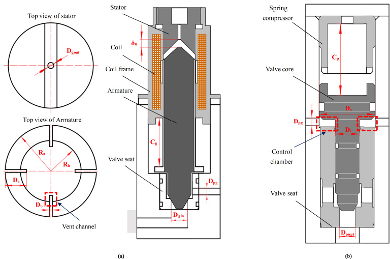
According to the requirements of the propulsion system for the size and weight of the valve, the structure model of PPHSV is established, as shown in Fig. 1. It consists of one pilot valve and two main valves. The pilot valve used to control the on/off of the high-pressure gas (N2) is an electromagnetic actuated, 3-way 2-position and normally closed valve. The main valves used to control the on/off of the fuel (MMH) and the oxidizer (N2O4) respectively are 2-way 2-position and normally closed valves.
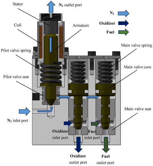
The structure of the proposed PPHSV.
The pilot valve is controlled by pulse width modulation (PWM). When the solenoid coil of the valve is energized, the magnetic force and the gas force of high-pressure N2 push the armature to overcome the spring force to open the valve and close the exhaust port of the stator. Thus, the high-pressure N2 flows into the control chamber of the main valves, and the main valves are opened respectively by the resultant force of the high-pressure N2 and the high-pressure propellants, then fuel and oxidizer flow into the injector through the main valves. When the solenoid coil has no current, the magnetic force disappears and the pilot valve closes rapidly under the spring force, which cuts off the supply of N2. Meanwhile, the exhaust port is opened to make the N2 in the control chamber flow out. Then the main valve cores reset under spring force to cut off the supply of fuel and oxidizer respectively.
Compared with the conventional HSV of the propulsion system in a spacecraft, the PPHSV proposed in this paper has the advantages of compact structure, high space utilization ratio, high integration, and low peripheral control complexity. However, the opening and closing time of the main valve cores of the proposed PPHSV are 69.1 ms and 92.5 ms, respectively, which cannot meet the requirements of response time (less than 60 ms). By directly changing some design parameters, the opening and closing time of the valve cannot be reduced synchronously, and even influences the normal operation of the valve. Therefore, on the basis of the prototype shown in Fig. 1, the response time of PPHSV is multiobjective optimized to meet the design requirements.
Mathematical model of the pilot valve
In order to obtain the analytical solution of the response time, it is necessary not only to accurately establish the dynamic model of the pilot valve subsystem and the main valves subsystem but also to fully consider the interaction between the two subsystems. Kirchhoff’s law, Maxwell’s equations, Newton’s second law of dynamic and the thermal equilibrium equation are applied respectively to the electric field, magnetic field, movement, and thermal field to calculate the response characteristics of the pilot valve. For the fast response of the pilot valve and the good heat dissipation of the coil, the temperature of the solenoid changes very little, which makes the resistance remain constant. Therefore, the thermal equilibrium equation is not considered in the mathematical model.
Electrical circuit mathematical model
The electrical circuit can be simplified with an ideal inductance L in series with an equivalent resistance R e , as is shown in Fig. 2.

Equivalent circuit of the solenoid valve.
According to Kirchhoff’s law, the electrical circuit mathematical model of the coil can be expressed as:

FEA model of the solenoid valve.
The method based on the equivalent magnetic circuit model has a great calculation error for the complicated magnetic field with a complex structure. The finite element method (FEM) based on the physical structure of the magnetic field can accurately simulate the magnetic field characteristics. The static characteristics of the proposed solenoid valve are simulated by the electromagnetic field simulation software ANSYS Maxwell. As the solenoid valve is an axisymmetric structure, in order to reduce the calculation amount, the 2-D axisymmetric model is adopted for numerical simulation, as shown in Fig. 3. The material of armature, stator and coil frame is Fe–Co alloy. The material of the coil is copper. The material of spring, seat and valve body are non-magnetic, which can be neglected in modeling. The simulation results of the magnetic force F m and inductance L with the change of the initial air gap δ0 and driving current I are respectively shown in Fig. 4. The electromagnetic force is parallel to the movement direction of the armature and points to the stator. The verification test is illustrated in Section 5.
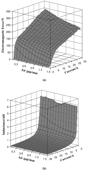
Simulation results of (a) electromagnetic force characteristics and (b) inductance characteristics.
According to Newton’s second law of motion, the resultant force acting on the armature when the valve opens can be expressed as:
The resultant force acting on the armature when the valve closes can be expressed as:
The movement of main valve cores follows Newton’s second law of motion, and the gas in the control chamber obeys the momentum equation, continuity equation, and energy conservation equation. The loss of gas is not considered in the dynamic process. Due to the response time of the main valves is extremely short and the size of the control chamber is very small, the control gas pressure and the density field in the control chamber are both assumed to be uniform fields in this paper.
Mathematical model of the main valve core’s movement
The resultant force acting on the valve core when the valve opens can be expressed as:
The resultant force acting on the valve core when the valve closes can be expressed as:
F
gx
and F
l
can be expressed as:
The dynamic equation of the control chamber can be expressed as:
Optimization model and objectives
During the opening and closing process of the PPHSV, due to the electrical hysteresis caused by the resistance of the coil inductance to the change of the current, the mechanical hysteresis caused by the movement delay of the main valve core, the fluid hysteresis caused by gas filling and discharge of the control chamber and the magnetic hysteresis, the main valve cores have a delay characteristic relative to the driving voltage. In order to improve the response performance of the PPHSV, the response time is taken as the optimization objective. The optimum response time can be expressed as:
The optimization design flowchart is shown in Fig. 5.
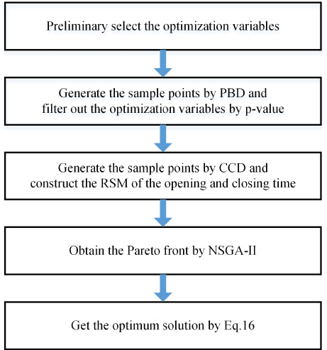
Design flowchart.
The opening and closing time of the PPHSV are respectively divided into three stages for analysis, and they are described by T on1, T on2, T on3, and T off1, T off2, T off3 as is shown in Fig. 6. Since we aim at to reduce the response time of the proposed PPHSV, the coupling effects between the response time of different stages are not counted in this study.
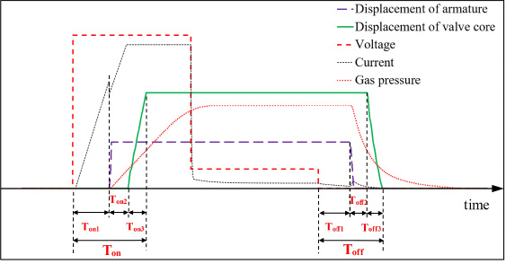
Schematic diagram of opening and closing processes.
T
on
is defined as the period between the time when the coil of the pilot valve is powered and the time when the main valve is fully opened. The first stage T
on1 of the opening time is the period between the start of T
on
and the time when the armature of the pilot valve begins to move, which means the opening delay time of the pilot valve and can be obtained by [30]:
The second stage T
on2 of the opening time is the period between the end of T
on1 and the time when the valve core begins to move, which can be expressed as:
Geometry diagram of (a) the pilot valve and (b) the main valve.
The third stage T
on3 of the opening time is the period between the end of T
on2 and the time when the valve core reaches the end of the stroke, which can be expressed as:
T
off
is defined as the period between the time when the voltage is cut off and the time when the main valve is completely closed. The first stage T
off1 of the closing time is the period between the start of T
off
and the time when the armature of the pilot valve begins to close, which means the closing delay time of the pilot valve and can be obtained by:
The second stage c of the closing time is the period between the end of T
off1 and the time when the main valve begins to close, which can be expressed as:
The third stage T
off3 of the closing time is the period between the end of T
off2 and the time when the main valve is fully closed, which can be expressed as:
14 parameters having an influence on the opening and closing time of the PPHSV are preliminary selected, which are partially shown in Fig. 7. The ranges of the optimization variables which are shown in Table 1 are determined by two requirements: first, the PPHSV should operate normally with a good safety margin; second, the value of the high level is about 1.25 times that of the low level.
The ranges of the optimization variables
The ranges of the optimization variables
If all variables are taken into account, the amount of calculation will be very large and the experiment resources will be wasted. It is necessary to select the variables that have a significant influence on T on and T off by PBD. PBD is a partial experimental design. The significance of every optimization variable is obtained by comparing the calculated results of optimization objectives at two levels of each variable.
First, two levels of high and low are selected for each variable, and 5 dummy variables are introduced to analyze the error, then 19 tests are performed. The results of the p-value of the variables are shown in Fig. 8. It can be seen that the p-values of gas pressure P g , number of turns N, spring pre-compression of the pilot valve δ a and orifice diameters of the main valves D gin are all less than 0.05. It means that these four variables have a significant effect on T on and T off , which are selected as the optimization variables in this paper.

P-values of each variable.
Central composite experiment design
CCD is used to obtain the sample points to establish the second-order RSM between the optimization objectives and variables. According to the results of the PBD, the design variables are P g , N, δ a , and D gin . Therefore, CCD is performed with 4-factors and 5-level. The values of 𝛼 used for axial point calculation is 2 and the central point is 1. The experimental design and results are shown in Table 2.
Design and results of the experiment
Design and results of the experiment
RSM is a method that replaces the real response surface by fitting an overall approximation of output variables to establish the approximate model. In this paper, a second-order RSM is used, and expressed as:
According to the results of CCD, the regression coefficient matrix is calculated by the least square method. The second-order RSM for T
on
and T
off
can be expressed as:
The p-valve, determination coefficient R 2 and variation coefficient CV of the model is analyzed. It can be concluded that: the p-value of T on and T off are all less than 0.0001, which indicates that the model has a high significance. The R 2 values are 0.9829 and 0.9989 respectively, which means that the model has a good correlation. The CV values are 4.77% and 1.37% respectively, which illustrates that the model has a good fit.
NSGA-II is a fast non-dominated sorting genetic algorithm with elitist strategy, the non-domination solutions of which distribute uniformly and converge well. It has become one of the benchmarks in the field of evolutionary multiobjective optimization. The optimization process can be expressed as [36]:
(1) Create the parent population P n of size n, and the offspring population Q n with the same size n is obtained through the usual binary tournament selection, recombination, and mutation.
(2) Combine population P n and population Q n to form a new population R n of size 2n, then the population R n is sorted to different nondominated fronts by the non-domination, and calculate the crowding-distance of all individuals in all fronts. Choose the best individuals needed in a new parent population P n+1 in the order of their ranking.
(3) Create a new offspring population Q n+1 by selection, crossover, and mutation. Combine the new population P n+1 and Q n+1 to form a new population R n+1.
(4) Judge whether the n is larger than the maximum evolutionary number. If yes, the algorithm ends; otherwise, the evolution continues.

Pareto front of the opening and closing time.
Comparison of parameters and results before and after optimization
The NSGA-II algorithm is adopted to search for the best solution to the established response surface model. The parameters of the algorithm are set as follows: the population size is 100, the maximum evolutionary generation is 300, the crossover probability is 90%, the mutation probability is 10%, and the deviation of the fitness function is 1 × 10−100. The optimization solution set of the response time is shown in Fig. 9, and the Pareto front is marked by the red line. Point B is the best solution according to the Eq. (15), and point A is the response time before optimization.
The parameters and the results before and after optimization are shown in Table 3. It can be seen that the opening time T on and the closing time T off respectively decreased by 17.7% and 37.4% after optimization.
Based on the above optimization, the prototype of the PPHSV is manufactured and assembled. In order to verify the simulation results of the magnetic force in Fig. 4, a static characteristic test is carried out to measure the magnetic force of the pilot valve. The schematic diagram of the test system is shown in Fig. 10.

Schematic diagram of the magnetic force test system.
The body of the pilot valve is fixed on a three grab chuck, and the armature is connected with the piezoelectric quartz force sensor (LANCE, LC0501). The air gap between the armature and the stator is adjusted by the adjusting knob. The solenoid valve is driven by a PWM signal of the driver. A laser displacement sensor (MEL, D-85386), a current sensor (AGILENT,1146A), a laser displacement sensor and a piezoelectric quartz force sensor are used respectively to measure the size of the air gap, the current, the displacement and magnetic force. All test data are transferred by a data acquisition system and transmitted back to the industrial personal computer (IPC) for further post-process. The results of the simulation and test are shown in Fig. 11. It can be noted the deviation of the magnetic force becomes larger with displacement. The most important reason is that the vent channel is neglected, which can cause large force in the armature. However, the deviation is relatively small and the measured data match well with the simulated results.
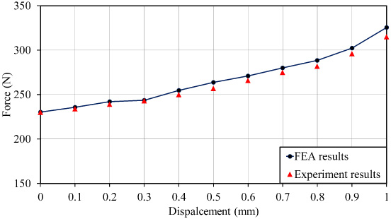
Static force-displacement of the simulation and test.
Aimed at verifying the accuracy of the MOO results, the response time of the PPHSV at the optimum design point is tested. Due to the toxicity of the fuel and oxidizer, H2O is used instead of the test. The experimental setup is shown in Fig. 12.
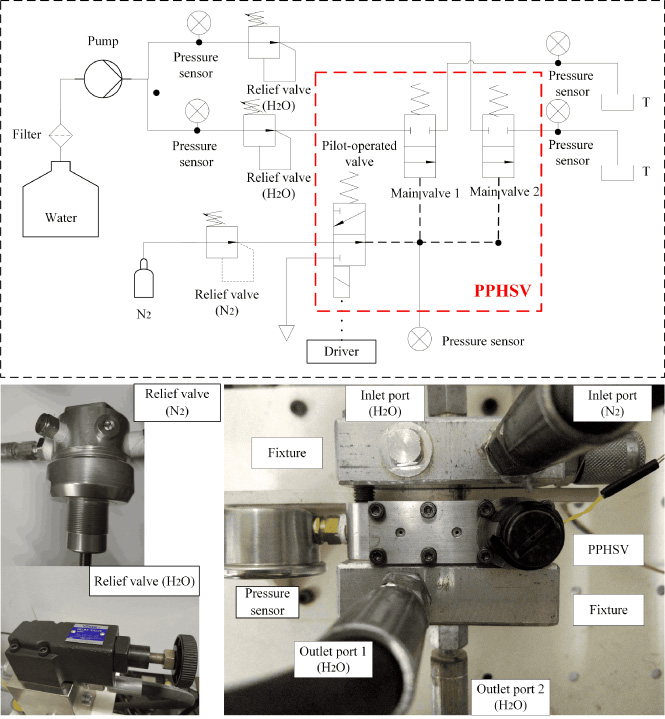
Experimental setup for the response performance.
The system gas pressure and water pressure are adjusted to the optimized values (5.6 MPa and 5.4 MPa) respectively by relief valves. The PPHSV is driven by a PWM signal with a duty ratio of 0.5 and a frequency of 1.25 Hz. A current sensor and a pressure sensor are used to measure the driving current and the water pressure at the outlet respectively. The displacement curve of the armature can be obtained by the pressure curve. The response performance of one cycle (800 ms) is shown in Fig. 13. The blue line is the current signal and the green line is the displacement of the main valve. T on is about 56 ms and T off is about 57 ms. The results are consistent with the optimized calculation values in Table 3. The deviations of T on and T off are less than 5%.
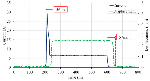
Experiment results of the response performance.
A PPHSV applied for the propulsion system in a LRE is proposed in this paper. At first, the mathematical models of the pilot valve and the main valves are established based on the analysis of the structure and working mechanism of the valve. Then the opening and closing time are taken as the optimization objective, and 14 parameters affecting the response time are preliminarily selected. The PBD is used for the factorial design of 14 parameters, and 4 optimization variables that have a significant influence on response time within a certain range are filtered out: gas pressure of system, number of turns, spring pre-compression amount of the pilot valve and the diameter of the valve orifice. The CCD is used to design the 4-factors and 5-levels experiment, and the opening and closing time of 25 sample points is calculated. The regression coefficient matrix is calculated by the least-squares method, then the second-order response surface model for the opening and closing time is constructed. The p-value, determination coefficient and variation coefficient of the model are analyzed.
NSGA-II is used to obtain the Pareto front of the response time. The optimum opening and closing time selected from the Pareto front are 56.9 ms and 57.9 ms, which reduce by 17.7% and 37.4% respectively compared with those before optimization. Then a prototype is successfully manufactured based on the parameters corresponding to the optimization results and the response time is tested. The deviations between the optimization results and the test results are not higher than 5%. The research results show that the optimization design method proposed in this paper is scientific and effective and can be applied to the multiobjective optimization design of PPHSV.
Footnotes
Acknowledgements
This research did not receive any specific grant from funding agencies in the public, commercial, or not-for-profit sectors.