
Abstract
Traditional nuclear magnetic instruments are not convenient for measurement in situ due to the closed magnet structure and heavy weight. It is crucial to improve tree planting by exactly detecting moisture parameters of living trees. To investigate this problem, an open and portable magnetic resonance sensor was proposed. In this work, we introduced unilateral magnetic resonance sensor which can achieve onsite nondestructive measurement of large-volume samples due to its open structure. To fit the shape of living trees, the region of interest was set in an arc region. A magnet structure was optimized by ANSYS software. Because the magnet has a constant natural gradient along radial direction, we need gradient fields in the other two directions (Z and Y). Z/Y gradient coils for unilateral magnetic resonance sensor are studied based on the Fourier series method. Current density in gradient coils is assumed as Fourier series composed of trigonometric functions. We introduced stream function to establish relationship between the current density and the winding structure, then constructed an optimization model by combining power dissipation with the deviation between calculated field and target field. The coils are manufactured using a flexible printed circuit board and measured by gauss meter. The measurement and simulation results are consistent. Measurement results of the gradient coils showed that the magnetic fields have good linearity which is helpful to realize 3D measurement in the upcoming work.
Introduction
It is crucial to improve tree planting by exactly detecting moisture parameters of living trees [1]. However, it is not convenient for investigating such parameters in situ by traditional nuclear magnetic instruments due to the closed magnet structure and heavy weight. Many researches on living plants have been performed in laboratories or greenhouses. Thus, a portable and noninvasive approach for outdoor mensurements is required. Akiyoshi Nagata [2] designed an outdoor magnetic resonance imaging (MRI) system for noninvasive, long-term measurements of sap flow in a living tree. The MRI system is a powerful tool for studies of water transport in outdoor trees, but it is still limited by the size of trees. The NMR-MOUSE [3,4] designed by B. Blümich is a transportable nuclear magnetic resonance (NMR) device, and the device allows the detection for any part of a plant due to its open structure. Based on the NMR-MOUSE, various portable structures called unilateral magnetic resonance sensor (UMRS) have been developed. The UMRS is an effective instrument for detecting samples of any structures, because it is nondestructive and has an open structure and small size [5–7]. Several researchers have studied on UMRS systems [8–10].
In this work, we constructed a UMRS for nondestructive detection of moisture in living trees. The region of interest was set in an arc region to fit the shapes of living trees. In general, the unilateral magnet has a constant natural gradient along the direction perpendicular to the surface of the magnet. In order to achieve three-dimensional (3D) measurement, we need gradient fields in the other two directions. The main magnetic field B y induced by the unilateral magnet designed by ourselves varies linearly along x-axis (shown in Fig. 1a). To realize the three dimensional localization of magnetic resonance signal, we just need the gradient fields in the other directions, such as z-axis and y-axis. Methodology used for designing gradient coils includes predetermined separation and distributed winding methods. The latter calculate gradient current density distribution according to a required magnetic field in the region of interest (ROI) then use dispersed or distributed windings to denote the current density, which was presented in Turner’s work [11]. On this basis, self-shielding coils [12] and gradient coils with minimum inductance [13] are extended. To obtain winding patterns that can be engineered, current streamline method was presented by A.E. William [14] and improved by M.A. Brideson [15]. We can easily obtain the winding structure of the coils by this method. In addition, there are other methods for coil structure designing, such as harmonic coefficient method [16], equivalent magnetic dipole method [17] and so on.
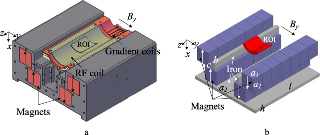
Unilateral magnet structure diagram and physical map. (a) is the model for simulation, (b) is the structure in detail.
Our team previously presented an equivalent magnetic dipole method [18,19] to design gradient coils for unilateral magnets, but the coils designed through this method are not closed at the boundary. To connect the wires, we add wire loops at the boundary artificially. In this paper, we introduced a Fourier series method for designing arc gradient coils, and solved the problem that the wires are not connected at the boundary. The current in a gradient coil was assumed to be continuously distributed on the cylindrical surface, and the current density in the wiring area of gradient coil was expanded into a Fourier series, which composed of trigonometric functions with a limited length and arc area. To obtain the coil winding structure, we used the stream function to discretize the current density on the cylindrical surface. Then, the magnetic field induced by Z/Y gradient coils was measured with a Gauss meter. The design methods and measurement results will be described in detail below.
The unilateral magnetic resonance sensor consisted of three parts: magnet structure, gradient coils and radio frequency (RF) coil. In this work, the designs of magnet and gradient coils are introduced emphatically.
Magnet structure design
The ideas of magnet structure design orinated from NMR-mouse [4] and V-shaped NMR sensor [20]. The sensor is composed of four magnet bars (NdFeB, N52, NingBo NingGang Permanent Magnetic Materials Co., Ltd.) and three iron bars/plates. Considering the processing technology, each magnet bar is made up of 7 small magnet bars (40 mm × 40 mm × 40 mm). The polarization directions of the magnet bars are shown in Fig. 1b. To facilitate the measurement of arc samples, such as trees, plastic pipes, breast and so on, this kind of unilateral structures inevitably have a natural gradient. In order to take advantage of this gradient for arc sample measurement, we adjusted the magnetic field to vary linearly with the radius of curvature by optimizing the parameters of magnets and iron (size and position). The region of interest (ROI) is an arc area (outside radius is 40 mm; inside radius is 30 mm; radian is π∕3), and the center point of the circular arcs is on the upper surface of the sensor. The optimum structure was obtained by FEM software (ANSYS, Pittsburgh, PA, USA), and the magnet field in ROI on xoy plane is shown in Fig. 2. According to the simulated structure, we made an actual structure of the magnet. We measured the magnetic field in the ROI by gauss meter (F.W. Bell8030) which was installed in the 3D stepper motor measurement platform (CH400B, CUIHAIJIACHENG, the resolution is 0.00032 mm), and the magnetic field measured in ROI on xoy plane is shown in Fig. 4. The magnetic fields of simulated and measured results along x-line in ROI were demonstrated in Fig. 5. There is a certain difference between the measured and simulated results due to the machining error. In spite of this, it will not affect the practical application.

Main magnetic field of simulated structure on xoy plane.

The actual structure of the manget made by ourselves.

Main magnetic field of actual structure measured on xoy plane.
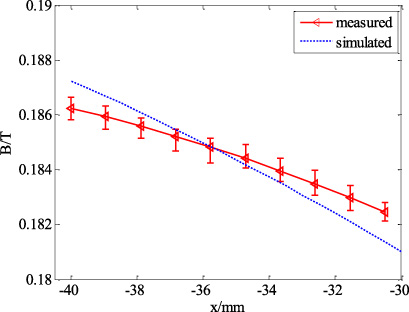
Main magnetic field of simulated and measured results along x-axis in ROI.
As shown in Fig. 1(a), tha main magnetic field B
y
has a constant gradient along x-axis, so we need to obtain gradient fields along z-axis and y-axis for realizing a 3D measurements by gradient coils. The wiring area of gradient coils is a cylindrical surface (radius is a), and the axial (z-direction) and circumferential (φ-direction) ranges are − L
z
∕2 ≤ z ≤ L
z
∕2 and −Φφ∕2 ≤ φ ≤ Φφ∕2, respectively. The calculation model is shown in the Fig. 6, and we established the cylindrical coordinate system due to the cylindrical symmetry of the model.
The components of current density can be expanded as a Fourier series consisting of trigonometric functions [21].
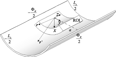
Analytical model of a cylindrical current surface.
The current density on the cylindrical surface satisfies 𝛻 ⋅
Hence, by substituting Eq. (2) or Eq. (3) into Eq. (5), the stream function can be expanded as a Fourier series.
The coefficients U
q
should be solved. To obtain the structure of the gradient coil, we established the relationship between the target field and current density. We can calculate magnetic field which is induced by each current element based on Biot–Savart’s law [24],
So, based on coordinate transformation principles between the cartesian coordinate system and cylindrical coordinate system, partial expression in Eq. (7) can be expressed as
In Eq. (9), G
𝜌, G
φ, and G
z
are
According to Eqs (7) and (9), the y-component of the magnetic field produced by current density
By substituting Eqs (10), (11), and (12) into Eq. (13), we can obtain dB
y
. Then according to the integral operation, the y-component of the gradient field in the ROI is given by
We assumed that current density evenly distributed along the thickness direction of wire. The thickness of each wire is h, and resistivity of the wire is 𝜌. So, power dissipation of the coil can be expressed as
Simulation results
The size of the wiring area was 200 mm in length along the z-axis, 2π∕3 in radian along the φ-axis, and 45 mm in the radius of the surface fit the size of unilateral magnetic structure. The ROI was a cylindrical surface with 35 mm in radius, π∕6 in radian along the φ-axis, and 12 mm in length along the z-axis. According to the method describled above, we obtained Z and Y gradient coils, and their structures and magnetic field distributions are shown in Figs 7 and 8, where the solid lines indicate the current flowing counterclockwise in the wires and the dashed lines indicate the current flowing clockwise in the wires.
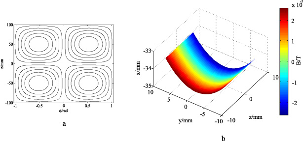
Z gradient coil structure and magnetic field. (a) is the winding structure of Z gradient coil, the solid lines indicate the current flowing counterclockwise in the wires and the dashed lines indicate the current flowing clockwise in the wires; (b) is the magnetic field induced by Z gradient coil in ROI.

Y gradient coil structure and magnetic field. (a) is the winding structure of Y gradient coil, the solid lines indicate the current flowing counterclockwise in the wires and the dashed lines indicate the current flowing clockwise in the wires; (b) is the magnetic field induced by Y gradient coil in ROI.
Two gradient coils (shown in Fig. 9) were fabricated by flexible printed circuit board (fPCB). Gradient coils were made of copper (0.07 mm in thickness), and the substrate was made of FR-4 (0.3 mm in thickness). We measured the magnetic field induced by each gradient coil in the ROI by gauss meter (F.W. Bell8030), and 3D stepper motor measurement platform (CH400B, CUIHAIJIACHENG, the resolution is 0.00032 mm) that was shown in Fig. 10. During measurement, we supplied 1 A current into each coil by DC power supply (Agilent 6654A, Keysight Technologies), and measured each sample point at 0.1 mm intervals. We have measured three times and averaged them. The resuls were shown in Fig. 11--Fig. 14.

Y and Z gradient coils made of flexible PCB.
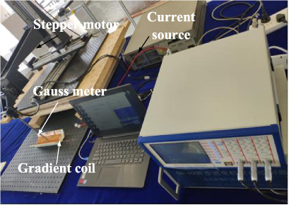
3D stepper motor measurement platform.
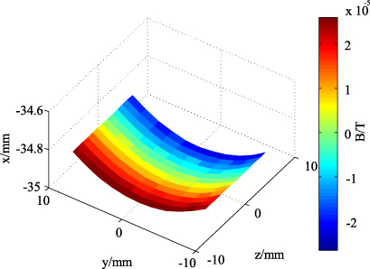
Measured magnetic field in the ROI induced by the Z gradient coil.
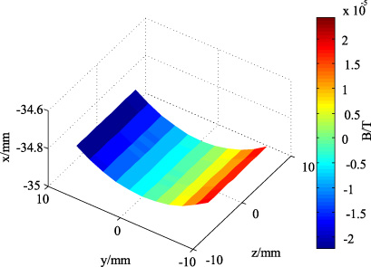
Measured magnetic field in the ROI induced by the Y gradient coil.
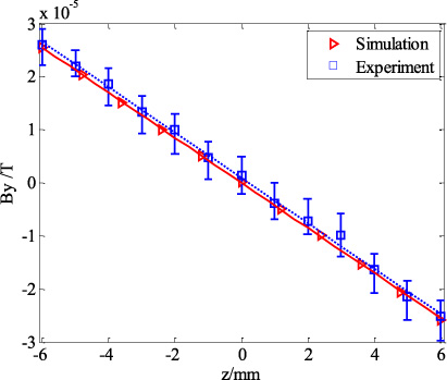
The magnetic field induced by the Z gradient coil in the ROI is shown in Fig. 11 and the magnetic field induced by the Y gradient coil in the ROI is shown in Fig. 12. The simulation and experiment results induced by the z gradient coil (along the z-axis) and y gradient coil (along the y-axis) are shown in Fig. 13 and Fig. 14, respectively. The measured magnetic field distribution indicates that the designed gradient coil almost meets the requirements. However, due to the uneven wiring caused by the connection between adjacent wires and processing errors, a certain deviation from the simulation results was observed.
Simulation and experiment results induced by the Z gradient coil.
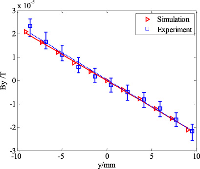
Simulation and experiment results induced by the Y gradient coil.
A unilateral magnetic resoance sensor used for arc shaped sample measurement was designed in this paper. Two unilateral gradient coils on a cylindrical surface were designed based on the Fourier series method. According to the restrictions of the wiring area, a Fourier series composed of trigonometric functions was introduced to express the current density within the required arc area. The magnetic fields induced by Z and Y gradient coils were measured, and the measurement results were in agreement with the simulation results. However, deviations caused by structural asymmetry were still observed due to the connection between adjacent wires. And the region with linear gradient is not large enough. In order to improve the gradient coils, the inductance and power minimization constraint will be considered in future.
Footnotes
Acknowledgements
This work was supported by the National Natural Science Foundation of China (Nos. 51677008 and 51707028), Fundamental Research Funds for the Central Universities (No. 2018CDJDDQ0017) and Science and Technology Funds of Chongqing Municipal Education Commission (KJ1600333).