
Abstract
Magnetorheological fluid (MRF) sealing technology has gained more and more attention in civil engineering, safety engineering, manufacturing, life science, aviation and so on, owing to its great pressure bearing capacity due to the viscous stress and controllable yield stress of MRF under external magnetic field. Even if overpressure occurs, magnetorheological seal (MRS) can restore the serviceability automatically with the help of magnetic field when pressure difference drops back. To have a deep understanding of magnetorheological sealing technique, the paper begins with an introduction of the basic features of MRF and relevant applications of MRS. Then several basic design issues of MRS structure are introduced. Furthermore, main factors influencing MRS performance are discussed on how to increase the pressure drop of MRS structure. In the end, modeling techniques of MRS structure are provided according to Bingham plastic model, Bi-viscous model, Herschel–Bulkley model and Herschel–Bulkley model with preyield viscosity, respectively, for calculating yield stress of MRF and pressure drop of MRS structure. Hopefully, this review can be regarded as a useful complement to other reviews on MRF technology and applications.
Introduction
Magnetorheological fluid (MRF), a type of smart material and firstly discovered in 1948 and patented in 1951 by Rabinow [1,2], is a suspension of magnetically responsive particles in a liquid carrier, and can flow freely like Newtonian fluid in the absence of an external magnetic field (off-state) [3,4], whose ferromagnetic particles distribute randomly in the liquid carrier and viscosity is controlled only by the particle volume fraction and viscosity of the liquid carrier [5–7]. When exposed to the magnetic field (on-state), it changes from the free-flowing liquid state into a semisolid condition in several milliseconds with its ferromagnetic particles forming chain-like structure that resists the fluid movement [8–10] as shown in Fig. 1. And this rheological changing behavior can be characterized by the variable yield stress depending on the magnetic field strength [11–13], only when the shear stress exceeds the yield stress, MRF comes back to free flow state with nearly unchanged plastic viscosity [14–16]. In addition, compared to the other field-induced smart materials, such as electrorheological fluid (ERF), MRF can reach higher magnetic field-induced yield stress (more than1000 kPa) with a magnetic field easily generated by lower voltage and less power consumption [17,18]. Moreover, due to its simple configuration, MRF devices have the ability to be made in a compact design [19–25].
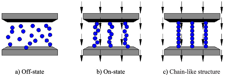
Activation of MRF under external magnetic field.
During the past few decades, MRF technology has gained significant developments in performance evaluation and fast growing applications in civil engineering, such as building structure [26–28], robot control [29] and bridge construction [30,31], safety engineering, such as shock isolation [32–34] and energy absorption [35,36], manufacturing, such as vehicle brake [8,37,38], clutch [39,40] and differential [41] and tool wear [42], life science, such as prosthetic knee [43–46] and limb [47], aviation, such as rotor machine [48–52] and aircraft wing [53] and so on. One of the most noticeable applications of MRF is magnetorheological seal (MRS), who belongs to a new contactless sealing form [54] with zero leakage [55–57], easy maintenance [58,59], long service life [60,61], high sealing reliability [61,62], low intrinsic friction torque [61,63], actual absence of wear of mating parts [61,64], good applicability for special working conditions like sealing corrosive and ecologically dangerous media [65,66] and so on within the allowable pressure difference range, since it can hold back the pressure medium leakage through sealing gap by taking advantage of the MRF sealing ring that has certain pressure bearing capacity due to the viscous stress and controllable yield stress of MRF under external magnetic field [67–72], which means that MRF in the sealing gap will not flow as long as the pressure bearing value of MRF sealing ring is not less than the pressure difference between the inside and outside of the system. Even if overpressure occurs, MRF sealing ring can restore the serviceability automatically with the help of magnetic field when pressure difference drops back [73,74]. Nowadays, MRS has been applied widely and successfully in different hydraulic and mechanical devices, such as MRF shock absorbers [33–35,75–77], MRF dampers [46,54,59,63,69,71,73], MRF brakes [37,45,78–80], MRF clutches [39,40,81–84], MRF controllers [85–88], MRF grips [89–91], MRF valves [70,92–95], MRF actuators [15,25,29,96,97], breakaway devices [98,99], rotary shaft mechanisms [100–103], chucking and clamping systems [71,104,105] and so on.
To have a clear insight into MRS technique, this paper is arranged by first elaborating on basic design issues of MRS structure in Section 2, and followed by main factors influencing MRS performance in Section 3. Then, modeling techniques of MRS structure will be discussed in Section 4, and a conclusion is given in the last section of this review.
Basically, for different application purposes, MRS structure can be designed with different configurations based on the following fundamental aspects: (a) MRF working modes, (b) coil configurations, (c) geometrical arrangements of sealing gap.
MRF working modes
An MRS device usually comprises of MRF, configuration of MRF operational modes and an electromagnetic circuit for controlling the magnetic field intensity or just a permanent magnet. Up to now, there are four well-known working modes in MRS devices, namely valve mode, shear mode, squeeze mode [106–110] and pinch mode [111–113] as shown in Fig. 2.

MRF operational modes.
The valve mode, also called flow mode, involves the fluid flowing as a result of a pressure gradient between two stationary plates, which is used in shock absorbers, dampers, controllers, grips, valves, actuators and rotary shaft mechanisms, and the magnetic flux lines are perpendicularly to the direction of flow motion. In shear mode, MRF is forced to flow directly between two parallel plates sliding relatively to each other with a certain speed, and the magnetic field also has the normal direction to the fluid flow. This mode is usually applied in dampers, brakes, clutches, breakaway devices, rotary shaft mechanisms and chucking and clamping systems. The squeeze mode involves the fluid running between two plates moving in the direction of magnetic field under dynamic or static (compression or tension) loadings, which has less application compared to the valve and shear modes, and is only suitable for small amplitude vibration and impact dampers [107–110,114–116]. As for pinch mode, different from the above three modes, it works by employing a simple orifice and arranges the magnetic poles axially that are separated by a non-magnetic spacer, who can generates a highly non-uniform magnetic field with curved magnetic flux whose direction is no longer perpendicular to the plates, and recently is used in MRF valve [111–113]. In general, MRS structure in MRS devices uses valve mode, pinch mode or combination of the two modes or even any combination of the two modes with the other two modes depending on the function of the system [108,117–121].
Usually, MRS structure employs electromagnetic coils to produce and control the magnetic field for the MR effect, even though in some cases, the permanent magnets, who can only generate constant magnetic field, can fulfil the same purpose. There are two main coil configurations for an MRS structure, namely placement of coils and number of coils used.
The placement of coils can be further divided into two sections, one is internal coil whose electromagnetic coil is laid inside fluid channel of MRS structure (Fig. 3) with its application is shown in Fig. 4 [108], and the other is external coil with its electromagnetic coil laid outside fluid channel of MRS structure (Fig. 5) whose application is shown in Fig. 6 [122]. Generally, compared to the external coil, the internal coil has the advantages of more compact design, faster response time, higher pressure capacity and less fluid leakage and has the disadvantages of harder to maintain and more heat interference due to its more complex design [70,71,123,124].

MRS structure with internal coil configuration.
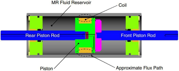
One MR damper using MRS structure with internal coil configuration [108].
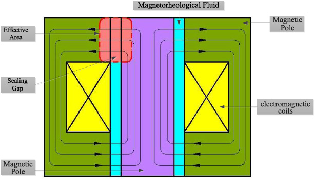
MRS structure with external coil configuration.

Schematic diagram of an MR mount using MRS structure with external coil [122].
As for the number of coils, it can be divided into single and multiple coils configurations [24]. The single coil is the simplest controllable way to provide magnetic flux to the MRS structure [125,126], while the multiple coils configuration uses two or more coils in the MRS structure that differs from the single coil configuration as it comprises more complex magnetic flux path within the MRS structure [110,118,127]. Normally, the multiple coils configuration as opposed to the single one can increase efficiency by minimizing overall inductance over resistance ratio that enhances electromagnetic circuit response time and manipulate the polarity to attract or repel the magnetic flux lines into effective region, which makes it more flexibility in controlling fluid behaviour but has the problems of more complex design and higher power consumption [76].
A better geometrical arrangement of sealing gap in an MRS structure can increase the effective region to make MRF get more intense MR effect to generate a higher pressure drop. There are three ways to configure the geometrical arrangements of sealing gap, the annular gap, radial gap (Fig. 7) [128] and multiple annular and radial gaps (Fig. 8) [129].

Annular and radial gap [128].
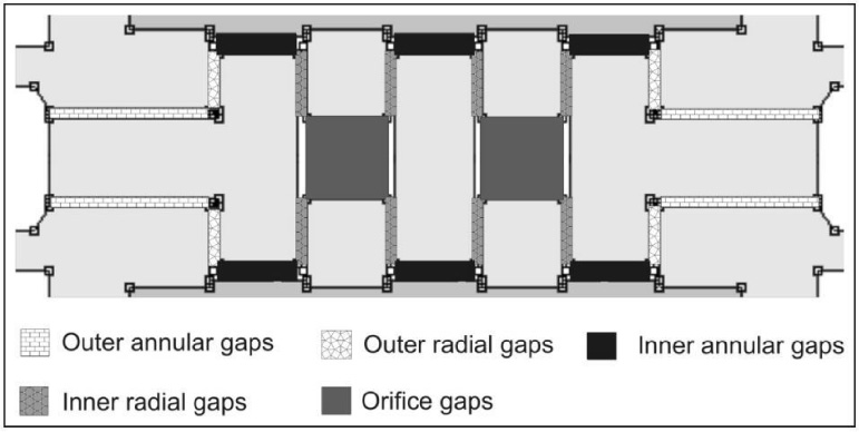
Multiple annular and radial gaps [129].
The annular gap, which is longitudinal to the axial flow of the fluid, is usually parallel to the inlet and outlet of MRS structure [126,128]. In contrast, the radial gap, which makes MRF flow transversally, is perpendicular to the inlet and outlet of MRS structure, whilst it benefits MRS structure with larger width and shorter longitudinal flow channel length for generating larger pressure drop, and has an easier and simpler fabrication, but is harder to design in compact size compared to the annular gap [130,131]. Consequently, the idea of combining multiple annular and radial gaps comes out, which can form a meandering flow path and achieve the best sealing performance of MRS structure among the three types of gaps due to the highest yield stress of MRF inside, as evident in previous works [24,110,127,132]. One of the easier ways to obtain multiple annular and radial gaps configuration is by using multiple coils arrangement, which however, will bring extra weight, complex design and larger dimension to MRS structure [70,133,134].
As is known to all, MRS shows an outstanding sealing performance in static or dynamic sealing conditions, which is mainly influenced by sealing gap distance, current intensity, dynamic viscosity, flow rate, rotating speed, working temperature, shape of pole piece and number of sealing stages.
Sealing gap distance
The sealing gap distance (size of annular gap or size of radial gap), called the thickness of MRF sealing ring and known as the most important variable, has a very significant effect on the viscous (pure rheological) pressure drop magnitude as well as the field dependent (magnetorheological) pressure drop magnitude as shown in Fig. 9 [129]. Meanwhile, the increase of sealing gap distance seems to have more influential effect on the reduction of field dependent pressure drop magnitude than on the viscous pressure drop magnitude, and as the sealing gap distance increased, the dominance of field dependent pressure drop degradation is started to overlap the viscous pressure drop degradation. The reason for this is that the decrease of sealing gap distance gives rise to significant increase of magnetic flux density [135,136], which leads to the increase of yield stress accordingly [133,137,138] that is mainly responsible for high field dependent pressure drop [139–141]. As mentioned above, it indicates that a smaller sealing gap distance is appreciated by MRS structure to get a higher pressure drop, but the sealing gap distance should not be too small, for the reasons that it will not only require a higher machining and assembly precision of MRS structure components, but also may cause jam effect of MRF within the sealing gap [142–144].
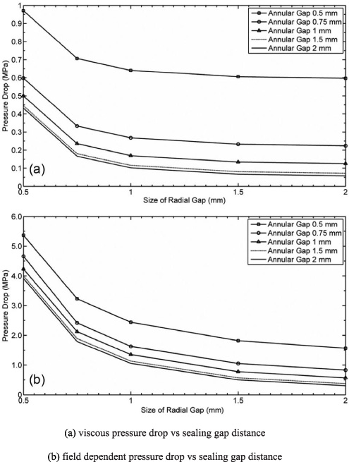
Effect of sealing gap distance on the pressure drop [129].
The current intensity of electromagnetic coil in a MRS structure is provided and adjusted by an external electrical current source, which has an effect on the magnetic flux density of MRF within the sealing gap. In general, the magnetic flux density steadily increases with increase of current intensity of electromagnetic coil until it reaches a saturated value due to the magnetic saturation of MRF in the sealing gap [137,145], and the same thing happens to the yield stress of MRF with respect to magnetic flux density as shown in Fig. 10 [105,146,147]. Here, the variation of yield stress will directly lead to a great change in field dependent pressure drop [148–150], which means that increasing the current intensity of electromagnetic coil can increase the field dependent pressure drop of MRF substantially until the saturation limit is approached.
Dynamic viscosity
The dynamic viscosity, also called off-state viscosity, is Newtonian fluid viscosity for MRF with no magnetic field applied, which is defined as the slope between the shear stress and shear rate [151,152]. Since increasing the dynamic viscosity can increase viscous pressure drop [139–141,148–150,153], MRF with a high dynamic viscosity is supposed to be selected normally to promote MRS performance, but the high dynamic viscosity will minimize the turn-up ratio (differences between off-state viscosity and on-state yield stress) of MRF [154–157], consequently it will weaken the MR effect seriously and minimize yield stress, which will result in too low field dependent pressure drop. It indicates that any attempt to maximize the dynamic viscosity to increase the viscous pressure drop will carry a great penalty in on-state yield stress that generates field dependent pressure drop. So a constant and acceptable dynamic viscosity may be the best way to produce a specified viscous pressure drop as well as maximize the turn-up ratio to achieve a maximum MR effect in order to generate a high field dependent pressure drop.
Flow rate
The flow rate is calculated as the area of sealing gap times the velocity of fluid movement, who has an important influence on viscous pressure drop. Generally, the viscous pressure drop increases proportionally to the flow rate [148–150,153], and the slope between viscous pressure drop and flow rate is only generated by the viscous resistance of the fluid. Both the flow rate and viscous pressure drop are a function of nondimensional plug thickness that represents the height of semisolid fluid that is not sheared in the sealing gap [117,145,158], which means that the plug thickness is used to control flow rate through the sealing gap as well as the viscous pressure drop across the sealing gap.
Rotating speed
The rotating speed also exerts a significant influence on both the viscous pressure drop and field dependent pressure drop [99,103] when MRF serves as a sealing medium for rotary shaft seal. It is well known that MRF presents shear thinning characteristic at high shear rate [155,159] that increases in proportion to the rotating speed [160,161], so it can be concluded that increasing the rotating speed extremely can decrease the dynamic viscosity obviously, which will lead to a sharp decrease in viscous pressure drop accordingly [148–150,153]. As for the field dependent pressure drop, it rises firstly and then declines with increasing the rotating speed, for the reason that, in the low dynamic regime of rotary shaft, increasing the rotating speed can increase the average number of parallel connections between individual aggregates composed of interacting particles of ferromagnetic dispersed phase of fluid, and decrease the size and the number of defects of the micro chain-like structure forming under magnetic field. Owing to that, the field dependent pressure drop grows [99,103]. When the value of the rotating speed exceeds some critical one, the shear thinning takes place, and the field dependent pressure drop begins to drop due to an intense progressive destruction of the micro chain-like structure, which is caused by the high rotating speed [151,159]. So, considering the bad effect of the high rotating speed, which gives rise to shear thinning of MRF, on both the viscous pressure drop and field dependent pressure drop, on the one hand, decreasing the rotating speed as far as possible, on the other hand, increasing the current intensity of electromagnetic coil to increase the magnetic flux density of MRF to generate enough yield stress for the field dependent pressure drop to compensate for the total pressure drop (sum of the viscous pressure drop and field dependent pressure drop) loss due to the high rotating speed [103,129].
Working temperature
The working temperature highly influences both the viscosity and yield stress of MRF [162] those have important effects on the viscous pressure drop and field dependent pressure drop [163,164], respectively, and as a result, the MRS performance is influenced by the working temperature. Generally, the viscosity and yield stress of MRF decreases with increasing working temperature, which leads to the reduction of the rheological properties that results in a bad effect on MRS performance and even the failure of MRS [165–168]. Once the influence rules of temperature on the MRS device under high temperature environment are mastered, the resulting unstable sealing performance can be compensated by other ways in the practical application so as to improve the MRS performance [169–171].
Shape of pole piece
The function of pole piece is to form magnetic circuit that enables the magnetic induction lines to pass though MRF in the sealing gap so as to form a MRS ring, and the shape of pole piece has an important influence on the magnetic field distribution, which mainly influences the yield stress of MRF that takes responsibility for the field dependent pressure drop, which has a close relationship with the MRS performance [172–174]. So, a good shape of pole piece should generate high magnetic gradient, high flux concentration and low magnetic reluctance in order to form a high strength MRS ring in the sealing gap to improve the sealing performance of MRS structure. There are mainly five kinds of shapes of pole piece, namely all plain ends, top and bottom chamfered ends, top and bottom filleted ends, all filleted ends and all chamfered ends as shown in Fig. 11, and it has been concluded that the pole piece with top and bottom chamfered ends, compared to the other four kinds of shapes of pole piece, can produce the highest magnetic flux density in the sealing gap at the same current when it has certain chamfer dimensions those have an important influence on the flow channel length [175]. So, choosing the pole piece with top and bottom chamfered ends may be a better way to obtain a higher pressure drop in MRS structure.
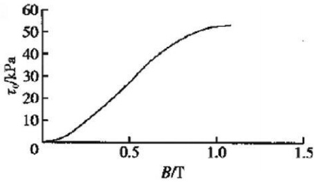
Yield stress τ0 vs magnetic flux density B curve of MRF-132-DG [146].
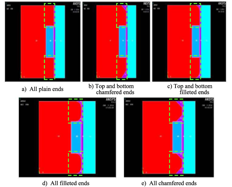
Different shapes of pole piece of axisymmetric piston profiles used for MRF damper [175].
Generally, the sealing burst pressure increases with increasing the number of sealing stages within a certain numerical range, since MRS ring can be formed at each pole piece in MRS structure with multiple sealing stages, and the total pressure drop of multiple sealing stages is the sum of that of each sealing stage [101]. But increasing the number of sealing stages blindly may cause a decrease in magnetic flux density of each sealing stage when the total magnetic flux is constant in magnetic circuit, which will result in a significant drop in total pressure drop and has little contribution to the MRS performance [176]. While the decrease in magnetic flux density of each sealing stage in multiple MRS structure can be compensated by increasing the current intensity to generate more magnetic flux, which may be a better choice to improve the multiple sealing performance [81].
Modeling techniques of MRS structure
The mathematical modeling of MRS structure is prevalently to calculate the pressure drop from the inlet to the outlet of the structure, where it can be usually found during the on-state of the MRS structure because of the MR effect under magnetic field. Generally, the pressure drop in MRS structure is calculated as the following equation:
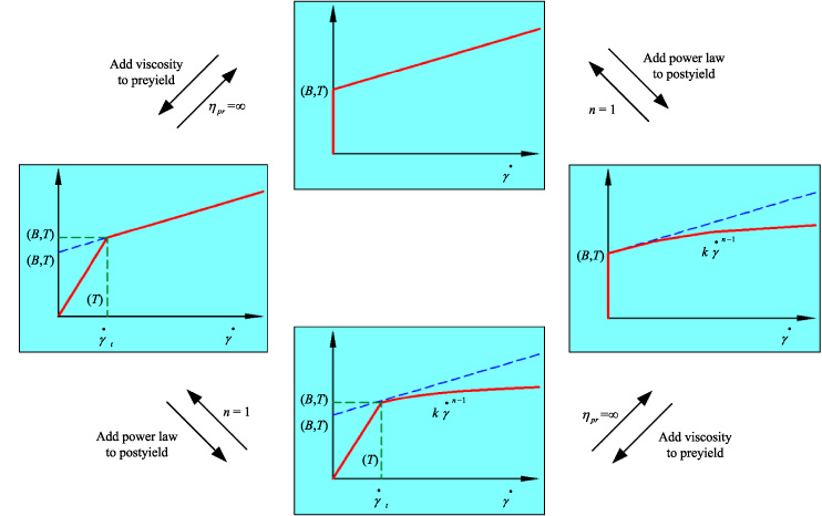
Relationship between the four models for MRF.
The BP model, firstly used to study the Bingham flow in the fluid path with parallel walls by Philips in 1969 [177] and to calculate the pressure drop of approximate rectangular duct of ER and MR valve by Gavin et al. in 1996 [178], regards MRF as a solid or plug in the pre-yield behavior that moves through the channel and Newtonian fluid in the post-yield regime, and has been widely used in modeling MRF [71,117,129,139], whose yield stress equation for field-dependent behaviour [141,149,153] with the temperature taken into consideration can be written as
The pressure drop equations in MRS structure derived from BP model are different for radial gap and annular gap that includes orifice, rectangular duct and cylindrical duct, those are listed in Table 1 [133].
Pressure drop equations derived from BP model [133]
From Table 1, Q is the flow rate of MRF in the flow channel, L is the active flow channel length, d is the sealing gap distance of the active flow channel, R
a
is the active flow channel radius that depends on cylindrical or rectangular duct, w is the active flow channel width, π is the pi constant number and c is empirical factor that varies from 2 to 3 and experimentally depends on what the ratio of the viscous pressure drop to the field dependent pressure drop, ΔP
v
∕ΔP
τ is present in MRS structure being considered. For ΔP
v
∕ΔP
τ ratios of approximately 1 or smaller, the value for c is chosen to be 2, For ΔP
v
∕ΔP
τ ratios of approximately 100 or larger, the value for c is chosen to be 3, where it can be approximately expressed as follows [133,149]:
The BV model is characterized by a high preyield viscosity behavior over a low strain range and a low postyield viscosity behavior over a high strain range. The transition from the preyield to the postyield condition takers place once the shear stress exceeds a transition stress [145,179,180]. The constitutive shear flow relationship for the BV mode [158,181] depending on the temperature is expressed as:
For the case where 𝜂 pr (T) approaches infinity or τ(B, T) = τ t (B, T), the preyield behavior of the BV model reduces to the behavior of the BP model as shown in Fig. 12. The pressure drop equations based on BV model deriving from series of works done by Yoo and his colleagues are shown in Table 2 [145].
Pressure drop equations based on BV model [145]
From Table 2,
Since MRF is generally observed to have a strong field-dependent yield stress that resists the material’s flow until shear stress reaches a critical value, after which fluid experiences postyield shear thinning or thickening effect, the assumption of constant viscosity based on the BP model may not be valid [150,151,159]. Then HB model is successfully employed to evaluate nonlinear postyield behavior of MRF, who is well known as an essential extension of the BP model. The temperature-dependent constitutive equation for the HB model is presented in Eq. ((9)) [183]:
Pressure drop equations derived from HB model [182]
From Table 3, Q is the flow rate of NQ
m
where N is number of active flow channel involved and Q
m
is the flow rate through each flow channel, 𝛼 is the function of n for dimensionless plug thickness and dimensionless shear stress where the value is provided in the study of Wang and Gordaninejad, A, T
∗ and
From the above three models compared, the BP theory is regarded as the ideal condition for modeling the yield stress and pressure drop of the MRS structure without considering the preyield and postyield behaviors of the MRF, while the BV and HB models are only used to account for the high viscosity of MRF in the preyield condition and shear thinning or thickening effect during the postyield condition, respectively. Then the HBPV model, also called viscous-power law model, comes out with the combination of preyield and postyield behaviors of MRF, whose constitutive equation [140,184] related to temperature is given as follows:
Behaviors of MRF in HBPV model [140]
The pressure drop equation for HBPV model defined by Hong et al. in 2008 is shown as follows [140]:
To sum up, the BP model is the simplest model due to its lest parameters involved, but it does not account for the preyield and postyield behaviors of MRF, which results in the lowest accuracy in calculation of shear stress of MRF and pressure drop of MRS structure. The BV and HB models are more accurate than the BP model, but they only concern with preyield and postyield conditions, respectively. The HBPV model, compared to the other three models, is the most accurate model because of its integration of preyield and postyield conditions of the MRF inside MRS structure even with most parameters.
An overview on magnetorheological seal is presented in this paper, including basic design issues of MRS structure, main factors influencing MRS performance and modeling techniques of MRS structure.
MRS structure uses valve mode, pinch mode or combination of the two modes or even any combination of the two modes with the other two modes depending on the function of the system, who works by allowing magnetic flux generated by electromagnetic coil to be guided into the active sealing gap to get the MR effect to generate a high pressure drop. To this end, the MRS structure can be configured by coil configurations carried out by using either placement of coils (internal coil or external coil) or number of coils (single coil or multiple coils), and geometrical arrangements of sealing gap carried out by using annular gaps, radial gaps or combination of both gaps in the MRS structure.
Sealing gap distance, current intensity, dynamic viscosity, flow rate, rotating speed, working temperature, shape of pole piece and number of sealing stages all have significant effects on the sealing performance of MRS structure, whose pressure drop, in this paper, can be calculated by BP model presenting the ideal condition of MRF behavior, BV model referring to the high viscosity of MRF in the preyield condition, HB model accounting for shear thinning or thickening effect of MRF during the postyield condition, and HBPV model standing for the combination of preyield and postyield behavior of MRF.
Footnotes
Acknowledgements
This work was supported by Key Science and Technology Program of Henan Province (No. 192102210050 and No. 172102210269) and Doctoral Found of Henan Polytechnic University (No. B2015-40).