
Abstract
This letter presents a bistable permanent magnet actuator, based on double wing magnetic flux (DWMF) formed by the structure of welding sleeve and slotted armature. The double wing magnetic flux consist of high wing magnetic flux (HWMF) and low wing magnetic flux (LWMF), resulting in bistable performance under differentiating control. Parameters improvement around DWMF is analyzed based on modeling, and optimized results for a prototype actuator are obtained. The experimental and simulation results agree well, and show that the prototype actuator can realize bistable performance under the DC step voltage drive, with the holding force of 8.2 N (without current) and the restoring force of −31.7 N (with negative current), the dynamic results show that the displacement response time within 8 mm is 28 ms, of which the actuation time is 16.5 ms, the transient maximum power consumption of the restoring period is 18 W.
Introduction
With the rapid development of electromagnetic technology, bistable permanent magnet actuators have been widely used in the field of aerospace, aviation, ships, automobiles and other environments with strict requirements on power consumption [1–8]. Due to the limited power supply for control device in the above field, low or zero power consumption has become a trend in development of electromagnetic actuator. Normally, it is available to maintain zero power consumption under polarized flux generated by permanent magnet, which keeps electromagnetic actuator in bistable position [9–11]. When the actuator is energized, excitated flux generated by power supply is added on polarized flux, and transfers one holding position to another holding position. When the actuator is unenergized, only polarized flux works at both holding position. Therefore, the characteristics of magnetic flux including polarized and excitated flux are the key factors to design bistable permanent magnet actuator.
The characteristics of magnetic flux in bistable permanent magnet actuator have attracted widespread attentions in recent years [12–15]. Axial magnetic flux is usually used in bistable permanent magnet actuator [11], and shows good holding characteristics, but is limited in deficient restoring force when the armature prepares to leave the holding position. Radial magnetic flux is used in high-force compact actuator [16], and shows high holding and restoring force by reducing air gaps and leakage flux and application of permanent magnets, but needs consume a lot of energy power at holding position or restoring period. To meet both bistable performance and low power consumption, it is an effective solution to optimize the magnetic flux in bistable permanent magnet actuator.
This letter presents a novel bistable permanent magnet actuator based on double wing magnetic flux (DWMF) formed by the structure of welding sleeve and slotted armature. Based on magnetic flux characteristics in the holding position, the bistable performance of the actuator is expounded. The effect of key structural parameters around DWMF on force characteristics of the actuator is discussed. The simulation results and the experimental results of static and dynamic characteristics are compared.
Theoretical analysis
Mathematical modeling
Neglecting the displacement current and the hysteresis, the following differential equations can be derived from Maxwell equations:
Where:
J is the source current density;
A is the magnetic vector potential;
μ is the permeability.
As the structure of the proposed bistable permanent magnetic actuator is symmetric. We could transfer (1) to (2) by cylindrical coordinate (𝜌, φ, z). Then a 3D problem can be a 2D one in case of axisymmetric magnetic field.
Where:
J = J φ e φ;
A = A φ e φ;
J φ is the source current density in φ direction;
A φ is magnetic vector potential in φ direction;
e φ is unit vector potential in φ direction;
As there may be partially saturated in bistable permanent magnet actuator, the nonlinear characterization of the magnetic material should be included in numerical simulation. The permeability μ is function of the magnetic field intensity B, which is
First boundary condition:
To compute the force on the armature, the system uses the principle of virtual work. According to the virtual work method, the total stored energy is
Based on ((2)), ((3)), ((4)), ((5)), ((6)), The force on the armature can be estimated by the following equation:
The bistable permanent magnet actuator model is established in 2D electromagnetic finite element software of Maxwell to investigate static force characteristic. Figure 1 gives the boundary and exciting conditions of the model for the bistable permanent magnetic actuator. Under a given voltage, the field current is specified in the coil winding. Except the default boundary conditions (first), symmetry conditions are assigned on the central axis, and the background object’s balloon (second) boundary conditions extend indefinitely along the edge. Figure 2 gives the grid mesh of the model for the magnetic actuator.

Boundary and exciting conditions of the model.

Grid mesh of the model.
Structure design for DWMF
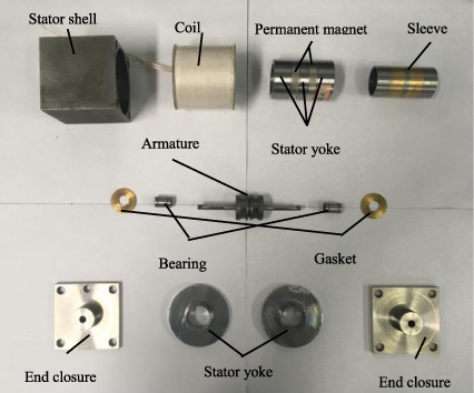
The actuator for investigation consists of end closures, stator yokes, sleeve, permanent magnets, stator shell, coil, armature, plunger, gaskets and bearings, etc. in Fig. 3. The sleeve is split into three parts by two separating rings and welded together. The armature is cut with three concentric square ring grooves, and is fixedly connected with the plunger by two pins. Two permanent magnet rings are arranged on the outer side of the separating rings, and placed opposite each other. Taking advantage of welding sleeve and slotted armature, the DWMF are formed as shown in Fig. 4(a), which consist of high wing magnetic flux (HWMF) and low wing magnetic flux (LWMF). When the coil is unenergized, both HWMF and LWMF has equivalent closed-loop polarized flux which passes through the permanent magnet, the stator yoke, the higher (or lower) part of the sleeve, armature, and the middle part of the sleeve, as shown in Fig. 4(a). When the coil is energized with a positive current, HWMF is strengthened, while LWMF is weakened, as shown in Fig. 4(b). Thus, upward force on armature becomes greater than downward force on that, which promotes the upward movement. Oppositely, the armature moves downward when the coil is energized with a negative current.

Actuator structure in a sectional view.
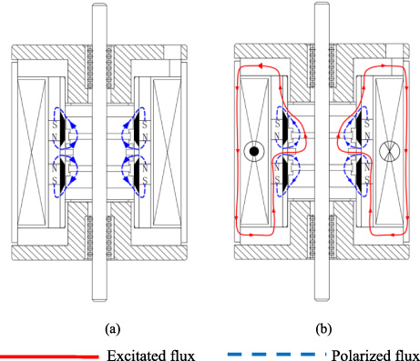
Working principle of DWMF. (a) Without current. (b) Positive current.
To estimate bistable performance of the actuator, according to electromagnetic field theory [11], electromagnetic model of the actuator can be simplified as a two dimensional problem. Based on modeling, magnetic flux distribution of the actuator at holding position is given in Fig. 5. F A represents attraction force at state “0” when the armature arrives at holding position with positive current; F H represents holding force at state “1” when the armature retains at holding position only by permanent magnets without current; F R represents restoring force at state “2” when the armature prepares to leave holding position with negative current.
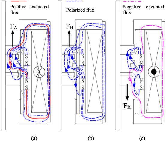
Magnetic flux distribution of the actuator at holding position (The armature displacement is 4 mm). (a) State “0” (Positive current). (b) State “1” (Without current). (c) State “2” (Negative current).
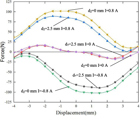
The simulation results show that the bistable performance could be explained by DWMF changes at holding position. At state “0” in Fig. 5(a), HWMF becomes stronger than the LWMF, resulting in upwards of the F A direction. At state “1” in Fig. 5(b), HWMF becomes weaker compared to state “0”, but is still stronger than LWMF, resulting in upwards of the F H direction, which represents stable holding function without current. At state “2” in Fig. 5(c), LWMF turns to be stronger than HWMF, resulting in downwards of F R direction, which is ready to transfer one holding position to another holding position. Figure 6 gives the effect of force characteristics under three different currents. The result shows no matter positive or negative currents, F R always keeps single force direction among the transfer process, so the actuator is able to transfer one holding position to another holding position, and can realize bistable performance based on DWMF.
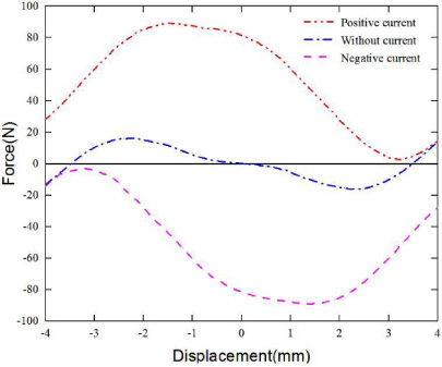
Effect of various current on force characteristics.
From the magnetic flux distribution, structural parameters of armature and sleeve around DWMF described in Fig. 7 have major effects on force characteristics in a limited space.
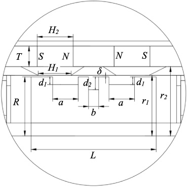
Structural parameters around DWMF.
The slotted armature includes two outer grooves and one inner groove, and the sleeve includes two separating rings. The three grooves and two separating rings are considered to be key factors to design DWMF, especially the inner groove. For example, the inner groove is help to distinguish HWMF and LWMF. The effect of inner groove on force characteristics can be analyzed based on modeling. When there is no inner groove, the holding force of F H is almost zero as show in Fig. 8, and the armature could not keep stable holding function without current. So DWMF formed by welding sleeve and slotted armature are helpful to realize bistable performance.
Comparison of displacement-force characteristics.
Besides, the influences of other structural parameters, such as depth d1 of armature’s outer groove, length b of armature’s inner groove, and thickness T of permanent magnet are analyzed to improve bistable performance based on modeling, which are omitted here. A prototype actuator could be obtained through the above process, as show in Fig. 9, and the detailed dimensions are shown in Table 1.
Main structural parameters of the actuator
Prototype of bistable permanent magnet actuator.
Figure 10 gives a test system for static and dynamic force characteristics of the actuator. The function generator (Tektronix AFG3021B) generates a control signal input to the actuator driver that provides control current for the actuator. The plunger of the actuator is connected to force sensor (CHLBS, accuracy 0.02%, range 50 kg), displacement adjusment mechanism, and a laser displacement sensor (optoNCDT ILd1700-50, sampling rate 2.5 kHz, range 10 mm) in order to keep in coaxial arrangement. Control box provides control signal for the motor which connect with displacement adjustment mechanism. The current, force and displacement are recorded on the Labview system. Thus, the static and dynamic force characteristics of the actuator can be calculated from the the obtained data or graph.
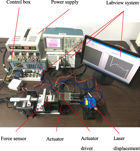
A test system for static and dynamic force characteristics of the actuator.
Figure 11 gives the static force-displacement characteristics of the actuator. The experimental results obtained under current of 0.8 A, 0 A and −0.8 A both have hysteresis curves. The hysteresis error is due to inevitable friction force existing in a moving armature. At the holding position of 4 mm and the current of 0.8 A, F A is 9.1 N. When the actuator is unenergized, F H is 8.2 N, and the armature is still able to remain at holding position. When the current is −0.8 A, F R is −31.7 N, so the armature would be pulled downward to another holding position of −4 mm. The situation is similar at holding position of −4 mm. The nominal value of the experimental curves is in accordance with the simulation one (marked as a dashed line), shows that DWMF proposed in the actuator is able to realize bistable performance.
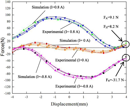
Comparison of simulation and experimental results of displacement-force characteristics in various current. (F A —Expermental attraction force, F H —Expermental holding force, F R —Expermental restoring force).
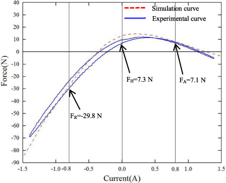
Comparison of simulation and experimental results of force-current characteristics (at displacement of 4 mm).
Figure 12 gives the static force-current characteristics of the prototype actuator at holding position of 4 mm. The hysteresis error is due to magnetic hysteresis existing in conducting material. The nominal value of the experimental curves is in accordance with the simulation one. The results show that under currents of 0.8 A, 0 A and −0.8 A, F A , F H , F R are respectively 7.1 N, 7.3 N, −29.8 N, and are accordance with DWMF function introduced in Section 3.2.
Dynamic response
In order to obtain the displacement response characteristics of the actuator, the displacement is measured in Fig. 13 under the DC step voltage drive of (25 V, 0 V, −25 V). The experimental results are in accordance with the simulation ones, except slightly lags behind the simulation curve, this is due to hysteresis effect not considered in simulation modeling. The experimental results show that the displacement response time within 8 mm is 28 ms, of which the actuation time is 16.5 ms, the movement time is 11.5 ms, the maximum current is 0.73 A during the restoring period. The dynamic response results also show that the actuator can realize the function of bistable performance under different polarity voltage.
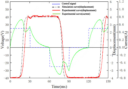
Dynamic response of actuator.
A bistable permanent magnet actuator based on DWMF is presented. Taking advantage of welding sleeve and slotted armature, DWMF consist of HWMF and LWMF. DWMF changes at holding position are able to realize bistable performance under different polarity voltage control strategy. Simulation model of the bistable permanent magnet actuator is established, and the magnetic flux distribution at holding position of 4 mm is compared with different drive currents. Parameters improvement around DWMF based on modeling shows that the structural parameters of slotted armature and welding sleeve are helpful to realize bistable performance, and provide theory basis for experimental development. The experimental and simulation results agree well and show that the prototype actuator can realize bistable performance under the DC step voltage drive of (25 V, 0 V, −25 V), with the holding force of 8.2 N (without current) and the restoring force of −31.7 N (with negative current). The dynamic results show that the displacement response time within 8 mm is 28 ms, of which the actuation time is 16.5 ms, the movement time is 11.5 ms, the maximum current is 0.73 A during the restoring period and the transient maximum power consumption of this period is 18 W.
Footnotes
Acknowledgements
This work was financially supported by key R&D Program Projects in Zhejiang, China (2019C02019).