
Abstract
This paper discusses the constants in various types Double Stator Permanent Magnet Brushless DC Motor (DSPM BLDC). Hybrid or electrical vehicles requires fast response motor that are capable of reacting as soon as possible. Thus, the motor should have a faster time response with lower electrical time constant, T e and mechanical time constant, T m . However, there are few literatures that reported the time response for a double stator topology. The time response relates to various constant parameters of the motor. It is known that double stator has high torque density which can be implemented for other applications in the future. For this research, various DSPM BLDC motors had been redeveloped. Finite Element Method (FEM) was used to simulate the characteristics of DSPM BLDC motor that considered the presence of the analytically calculated T e and T m . The results show that the Double Stator Slotted Rotor Permanent Magnet Brushless DC Motor (DSPM-SR) had good performance such as highest back emf, torque and good time response. A prototype of DSPM-SR had been manufactured and measured. The percentage differences between Analytical-FEM and Analytical-Mea for T e and T m were 4.2% and 9.1%, respectively. As a conclusion, this paper reveals the constants that could affect the performance of double stator topology.
Introduction
Permanent Magnet Brushless DC (BLDC) motor is widely used in many low cost applications due to its advantages, which are less noise, long life application, more efficient and many more [1–7]. The production of torque for BLDC motor can be improved by using a double stator because the conventional BLDC motor uses only the single stator. There are several important parameters that need to be considered in electric motor including constants. These constants will definitely affect the dynamic performance including the response of the motor. The parameters required in order to calculate the constants are coil resistance, inductance, back electromotive force (emf) and torque constant of the motor.
Due to the demand of applications that require fast response like hybrid or electric vehicles, a fast response motor is needed to provide essential acceleration when operating as a motor. Other than that, the engine of hybrid or electrical vehicle will be off while stopped at the traffic light and automatically restart the electric motor again when the driver releases the brake pedal. Faster initial response is required for better performance of electrical motor. For this condition, higher electrical time constant should be avoided to ensure good response between the driver and the car itself. Another condition that needs fast response is depends on the environment for the vehicle. For instance, when the car climbs the hill, low electrical time constant and low mechanical time constant are required. This is because, when the car climbs the hill, it will accelerate faster due to the response of motor towards the car. Meanwhile, when the car moves downhill, the response of braking will be more efficient because the inertia needed is low. Thus, a proper design of electric motor that could have a low electrical and mechanical time constant could contribute to better response between the driver and the car.
In addition, the time response for a double stator is unfamiliar among the researchers. Some of them studied time response on the single stator. Mikerov et al. stated that, the accentuation to the most important index depends on a servo drive application and design [8]. For a gear drive, the focus may be on the mechanical time constant, while for a gear- less (direct) drive, the electrical time constant becomes more important, which defines the servo drive bandwidth. Meanwhile, Han et al. stated that, to design BLDC Motor, it will be more accurate in both the time and frequency domains if the electrical time is considered constant [9].

Selected DSPM BLDC motor for comparison.
In an ideal case, the time response can be determined based on the motor itself. All the constants can be determined by using simulation by FEM and analytical equation. In the research by Bremner et al., they tested the performance and application of split rotor motor having variable voltage and torque constants [10]. The rotor was split into half. As the rotor halves were indexes relative to one another, the torque constant and voltage constants were varied. This increased the constants power speed range. During indexing, the torque and voltage constants were reduced. By reducing the voltage and torque constants at high speed, the back emf was reduced, allowing the motor to operate at a higher speed.
Kim et al. proposed a sensorless control algorithm of a three-phase BLDC motor. The back emf can be calculated from the electrical voltage equation but it had some errors at the commutation period. This error can be reduced by using the proposed sensorless control algorithm which is derived by using the mechanical and electrical equation simultaneously for the accurate estimation of the back emf constant [11]. Nakai et al. proposed a sensorless control by detecting the back emf. The back emf was detected by using a back emf estimation observer. The method was able to derive the estimated angle error and also estimate the angular velocity directly. To estimate the angular velocity, the disturbance observer was applied [12].
Besides that, Mizuno et al. had designed an optical scanner based on spring, damping, torque, electrical and mechanical time constants. A few methods were stated on how to decrease the mechanical time constant. The first method was by increasing the back emf constant and torque constant. In order to increase the back emf and torque constant, the size of the permanent magnet should be increased, thus increasing the magnetic flux. Meanwhile, to decrease the mechanical time constant, the inertia should be decreased by decreasing the mass of object [13].
Most of the literature studied time response on single stator but none for the double stator [14–16]. Previously, many researchers presume that the time constant will only affect the transient behavior of the machine and not the steady state behavior which is true if it is a brush DC motor. Meanwhile, for brushless DC motor electronic commutation of turning ON and OFF the discrete device such as MOSFET and IGBT for switching will provide continuous transient behavior periodically which will affect the steady state behavior. Therefore, this paper discusses in details about the consideration of various constants for dynamic torque in several types of DSPM BLDC motors that could affect the time response. It focuses on the parameters that influence the time response for a double stator topology. The structure and the motor sizing of various DSPM BLDC motors are shown in Section 2. The analysis method used is shown in Section 3. In Section 4, the effect of constant is presented and the best performance was selected for fabrication and measured experimentally. The result verification is shown in Section 5 and lastly, Section 6 concludes the constant in various types of DSPM BLDC motor.
There are three types of DSPM BLDC motor with different types of rotor structure developed based on other literature reviews [17–22]. They are the Double Stator Interior Permanent Magnet Brushless DC Motor (DSPM-IP), Double Stator Spoke Type Permanent Magnet Motor (DSPM-ST) and Double Stator Slotted Rotor Permanent Magnet Brushless DC Motor (DSPM-SR). All DSPM BLDC motor had designed for 18 slots 20 poles in three-phase systems. The fixed parameters are diameter of outer stator, stack length, total volume of magnet and mechanical air gap between outer and inner stator. The total number of turns for all models and the total volume of permanent magnet used are fixed to ensure equal magnetic energy by each model. Since some of the rotor of DSPM BLDC motor are made up from non-ferromagnetic material, the electromagnetic air gap is bigger compared to the rotor that made from ferromagnetic material. But, the mechanical air gap for all model is fixed which is 0.5 mm for both outer and inner stator. It is to ensure the stator and rotor do not touch each other. The structure of these DSPM BLDC motors can be shown in Fig. 1. Table 1 shows the motor sizing of a DSPM BLDC motor.
Parameters of DSPM BLDC motor
Parameters of DSPM BLDC motor
The outer and inner stators and rotor are made up from ferromagnetic material (Non-oriented silicon steel M250-35A). Figure 2 shows the B-H curve for non-oriented silicon steel M250-35A. It shows that the ratio of flux density to field strength (B/H) is not constant but varies with flux density for ferromagnetic materials. The flux density increases in proportion to the field strength until it reaches a certain value. This occurs if it stops increasing to the highest level and remains constant as the field strength continues to increase. The flux density maximum limit or being saturated for this material is about 2 Tesla. But to achieve an optimum result, 1.5 Tesla is the best selection. This B-H curve is imported into Ansys Maxwell properties.

Non-oriented silicon steel M250-35A B-H curve.
In this research, FEM was used to determine the constants of all DSPM BLDC motors using the ANSYS Maxwell software. Initially, every type of DSPM BLDC motor was modeled according to the motor sizing in Table 1. The electrical and mechanical parameters were set into FEM. The FEM condition that used is non-linear analysis with transient condition. There were five different sizes of copper diameter used in the analysis which are 0.4 mm, 0.6 mm, 0.7 mm, 0.8 mm and 1.0 mm. Table 2 shows number of turns since the diameter of copper used is different. Then, FEM is used to simulate in order to get the value of back emf and torque. The torque that does not consider the electrical time constant is known as the ideal torque, T ideal . The ideal torque refers to the amount of torque produces at some speed of rotation with load applied. Based on this result, the back emf constant and k e , torque constant, k t , were calculated in order to find the value of electrical time constant, T e , and mechanical time constant, T m . After that, the estimated input current that had considered T e was used in order to get the other torque known as the real torque, T ideal . The real torque is the torque produced after considering the time constants. Theoretically, the real torque produced is lower than ideal torque. The analysis was conducted after all three models were simulated. Figure 3 shows the flowchart of the analysis methodology.
Number of turns
Number of turns
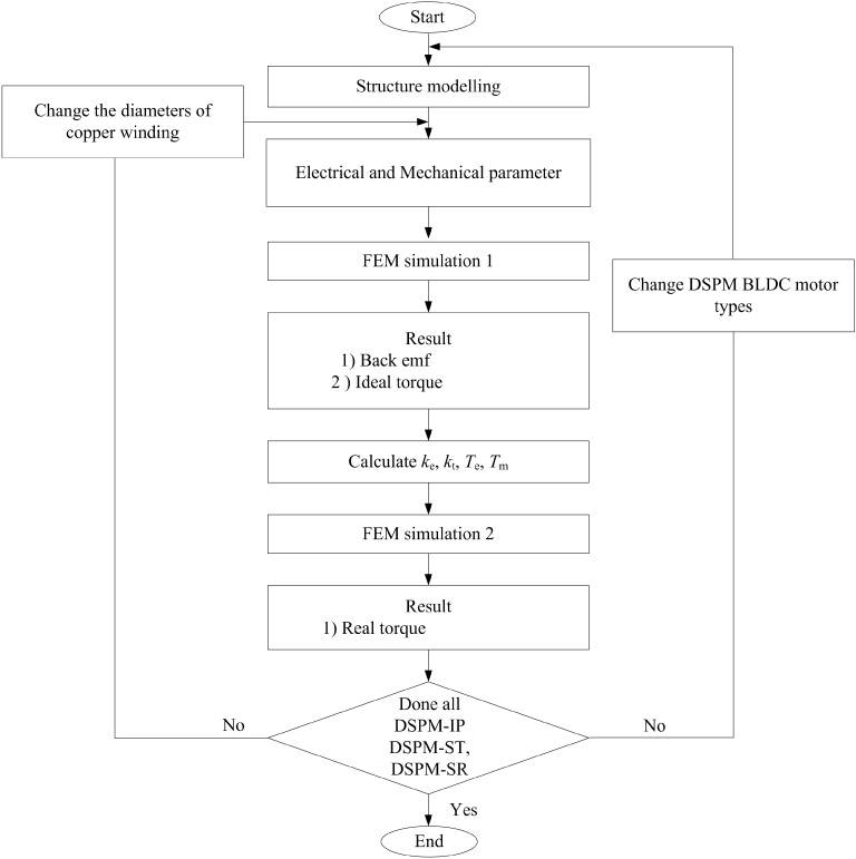
Analysis methodology.
The motor electrical time constant, T
e
is the time required for the current to reach 63.2% of its final value after zero source impedance stepped input voltage is applied to a motor [23–27]. There are two main parameters involved when calculating the electrical time constant, T
e
, which are total resistance, R
T
, and self-inductance, L, shown in ((1)). Since the DSPM BLDC motor has two stators, the value of resistance also should have two values which are resistance at the inner stator, R
inner
and resistance at outer stator, R
outer
. Both the values must be added to calculate the R
T
.
Analysis DSPM-IP.
Constants for DSPM-IP
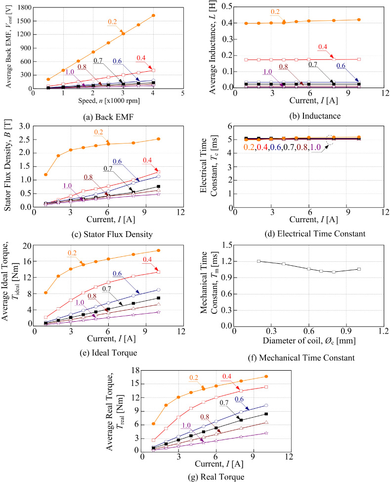
Figure 4 shows the characteristics of back emf, inductance, flux density, ideal torque, real torque, electrical time constant, and mechanical time constant of DSPM-IP. All the values plotted in this graph were taken from the data for various sizes of copper of DSPM-IP. For example, when the coil wire diameter is 0.7 mm, the number of turns is 55 while the electrical time constant and the mechanical time constant are 5 ms and 1.02 ms, respectively. From Fig. 4(a), the average back emf is gradually increased as the speed increases. It can be seen that the highest back emf is shown by 0.2 mm of coil wire diameter which is 1600 V for the speed of 4000 rpm. The lowest back emf is shown by 1.0 mm of wire diameter which is 55 V for 4000 rpm.
Figure 4(b) shows the inductance of DSPM-IP. The value of inductance produced is almost similar, even though the current is increased. The highest inductance is produced when 0.2 mm of coil wire diameter is used because the number of turns is the highest compared to other sizes of coil wire diameter.

Analysis DSPM-ST.

Analysis DSPM-SR.
The flux density produced at the stator of DSPM-IP does not reach the saturation level, even when 0.4 mm of coil diameter is used as shown in Fig. 4(c). This is due to the rotor material of DSPM-IP which is made from non-ferromagnetic material. Since the flux density does not reach the saturation level, the inductance will not change, even though the current is increased up to 10 A. Since the total number of each coil is different, the value of resistance will also be different. After obtaining the value of resistance and inductance, the next process is to find the electrical time constant, T e . From Fig. 4(d), the significant difference of T e is too small as the difference in inductance is very small.
Summarization of DSPM BLDC motor constant
The average ideal torque is increased when the current increases, as shown in Fig. 4(e). The average ideal torque is directly proportional to the current. The highest torque is produced by 0.2 mm, while the lowest torque is produced by 1.0 mm. Since the ideal torque increases, the flux density also increases as shown previously in Fig. 4(c). The 0.2 mm coil diameter has the highest T m as shown in Fig. 4(f). This is because it has a higher back emf, torque, and also resistance. On the other hand, the mechanical time constant decreases as the wire diameter increases. A smaller wire diameter makes the mechanical time constant higher compared to a larger wire diameter. In particular, the mechanical time constant is decreased from 1.2 ms to 1.0 ms when the coil size is changed from 0.2 mm to 1.0 mm. In order to minimize the value of the mechanical time constant, the size of copper needs to be increased.
Then, the real torque can be obtained after considering the values of T e and T m . The current injected to the real torque considers the switching characteristic of the driver. Figure 4(g) shows the average real torque of DSPM-IP. The real torque produced is lower than the ideal torque because the real torque has considered the existing inductance and the constant. As a conclusion, the DSPM-IP is not suitable for high torque applications because the torque produced is low.
Figure 5 indicates the analysis performance of DSPM-ST which includes the analysis of back emf and ideal torque, followed by inductance and flux density. The electrical time constant and mechanical time constant were analyzed and lastly, the real torque was obtained. Figure 5(a) shows the average back emf for DSPM-ST. The 0.2 mm coil wire diameter produces a higher back emf compared to other sizes of coil which is 500 V. When the 1.0 mm coil wire diameters is used, the back emf produced is about 30 V. The back emf is directly proportional to the speed. When the speed increases, the back emf will be increased.
The inductance was calculated after the ideal torque was obtained. It can be seen in Fig. 5(b) that the inductance produced by each size of coil is almost maintained. The highest inductance produced by the 0.2 mm coil wire diameter is 1.2 H. This is because the flux density exceeds the saturation level. Based on Fig. 5(c), the highest flux density produced is more than 2.0 T for the 0.2 mm coil wire diameter.
In order to obtain the electrical time constant, T e , the resistance of each size of coil must also be calculated. The value of T e is almost constant for all coil wire diameters as shown in Fig. 5(d). This is because when the inductance is higher, the value of resistance is also higher.
Based on Fig. 5(e), the average ideal torque is increased as the current is increased, but there is only a small significant difference of torque for each coil wire diameter. Since the number of turns for the 0.2 mm coil wire diameter is the highest, the ideal torque produced by the 0.2 mm coil wire diameter will also be the highest.
From Fig. 5(a) and (e), the mechanical torque constant, T m can be obtained. The 0.2 mm coil wire diameter has the highest T m as shown in Fig. 5(f). This is due to higher back emf, torque, and resistance. The resistance for 0.2 mm coil wire diameter is the highest because the number of turns is the highest. Fig. 5(g) shows the average real torque of DSPM-ST. The highest real torque produced is when the 0.2 mm coil wire diameter is used. As a conclusion, the DSPM-ST is not suitable for high torque applications because the torque produced is low. Even though the stator flux density achieved 1.5 T, the torque produced was low because there were more flux leakages circulated around the rotor of DSPM-ST.
Constants for DSPM-SR
Figure 6 shows the analysis performance of DSPM-SR motor. Figure 6(a) shows the back emf of each size of copper under various speeds. The back emf is directly proportional to the speed. When the 0.2 mm coil wire diameter is used, it produced the highest back emf which is 5000 V at 4000 rpm. This is because the number of turns used is the highest compared to others. Since the total number of turns for 1.0 mm coil wire diameter is the lowest, the back emf obtained is the lowest which is 200 V.
Figure 6(b) shows the average inductance. The inductance for coil wire diameter below 0.6 mm is decreased when the current is higher. This is due to the flux density saturation. When the flux density reaches the saturation level which is more than 1.5 T, the inductance will be decreased. As can be seen from Fig. 6(b) and (c), for 0.4 mm coil wire diameter with 3 A of current, the flux density is almost saturated, and the inductance is decreased.
From Fig. 6(d), the electrical time constant, T e is maintained until the flux density achieves the saturation level. Then, the T e starts to decrease as the inductance increases. The maximum electrical time constant is almost 12 ms. Figure 6(e) shows the average torque generated by DSPM-SR. The torque is simulated under various current values. At current 10 A, the highest torque will be produced for each size of copper. The highest torque produced is 29 Nm for wire diameter of 0.4 mm.
On the other hand, the mechanical time constant, T m decreases as coil wire diameter increases as illustrated in Fig. 6(f). Smaller coil wire diameter contributes to a higher mechanical time constant compared to larger wire diameter of coil. In particular, the mechanical time constant is decreased from 1.0 ms to 0.32 ms. In order to minimize the value of the mechanical time constant, the size of copper needs to be increased. The 0.2 mm coil diameter has the highest T m . This is because it has a higher back emf, torque, and resistance.
Figure 6(g) shows the average real torque of DSPM-SR. The real torque produced is lower than the ideal torque because the real torque considers T e and T m . As a conclusion, the DSPM-SR is suitable for high torque applications because the torque produced is high.
Analytical-Fem and Analytical-Measurement for fabricated DSPM-SR
Analytical-Fem and Analytical-Measurement for fabricated DSPM-SR
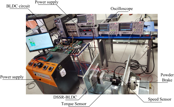
Experimental Setup for DSPM-SR.

Exploded view of DSPM-SR for fabrication.
Verification of DSPM-SR.
Based on the analysis in the previous section, there were three types of DSPM BLDC motor that can be selected in the selection of DSPM BLDC motor. In addition, there were several criteria such as the copper size and constant parameters of the DSPM BLDC motor. In terms of copper size, there were five different copper sizes used. The maximum flux density at the stator of less than 1.5 Tesla (T) was chosen for the coil selection. Meanwhile, in the fabrication selection, there are some parameters that must be fulfilled such as high back emf constant, high torque constant, low electrical time constant, and low mechanical time constant. Based on the analysis, it is confirmed that the suitable copper size is 0.7 mm. This is because when the rotor is made from ferromagnetic material, the maximum flux density achieved is about 1.5 T for 6 A of current.
Table 3 shows the summarization of various types of DSPM BLDC motors. The back emf constant for DSPM-SR is 0.1053 V which is the highest compared to others. The percentage between the highest and the lowest back emf constant is 89.8%. Meanwhile, the highest torque constant and the lowest are DSPM-SR and DSPM-ST, respectively. Each of them respectively produced 1.94 Nm/A and 0.1066 Nm/A. Besides that, the DSPM-IP produced the lowest electrical time constant which is 5.086 ms and DSPM-ST produced the highest electrical time constant which is 18.1555 ms. Finally, the last parameter constant that needs to be considered for fabrication is the mechanical time constant. The lowest mechanical time constant is 0.371 ms produced by DSPM-SR. To summarize, the DSPM-SR showed higher back emf constant, higher torque constant, and lower mechanical time constant; but, in terms of electrical time constant, the DSPM-SR was higher than DSPM-IP. Even though the electrical time constant for DSPM-SR was higher compared to others, it was chosen for fabrication because it fulfilled most of the criteria.
Result verification
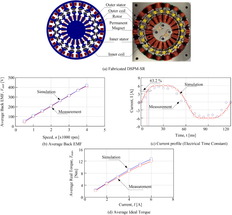
After selected DSPM-BLDC motor is chosen for fabricated, the motor is tested experimentally in order to verify its performance. The experimental setup is shown in Fig. 7. The experiments are conducted to validate the simulation result. Figure 8 shows the exploded view DSPM-SR for fabrication. It consists of shaft, casing, bearing, inner and outer stator, rotor, permanent magnet and rotor filler. The function of rotor filler is to make sure the rotor and permanent magnet is aligned with each other. Figure 9 shows the fabricated motor that used for simulation and result verification of DSPM-SR. The fabricated DSPM-SR is shown in Fig. 9(a). The stators and permanent magnet are made from non-oriented silicon steel M250-35A and Neodymium Boron Iron (NdFeB 42), respectively. The average back emf is directly proportional to the speed as shown as Fig. 9(b). The maximum average back emf (4000 rpm) for FEM simulation and measurement is 421.27 V and 412.88 V, respectively. The percentage different between them is 2%. Besides that, the back emf constant for FEM and measurement is 0.1053 V and 0.1059 V, respectively. Hence, the percentage difference is less than 1%.
The current injected to the DSPM-SR had considered the electrical time constant as shown in Fig. 9(c). It shows that the current from FEM and measurement has good agreement with each other. The values of T e and T m for fabricated DSPM-SR presented as shown in Table 4. Analytical-FEM means combinations of parameter values resultant from FEM into analytical equation. For example, to calculate electrical time constant the value of inductance is taken form FEM and resistance is calculated analytically. Meanwhile, Analytical-Mea means combinations of parameter values resultant from measurement into analytical equation. The Analytical-FEM and Analytical-Mea are 11.4 ms and 11.9 ms, respectively. The mechanical time constant by using Analytical-FEM and Analytical-Mea is 0.371 ms and 0.408 ms, respectively. The percentage error between them is 9.1%. Analytical-FEM means that the value from FEM was used to calculate the T e and T m . Meanwhile, Analytical-Mea means that the value from measurement was used to calculate T e and T m . The percentage difference is 4.2%.
The average real torque is as shown in Fig. 9(d). It is noted that the average real torque is directly proportional to the current. The minimum average torque produced by FEM is 2.34 Nm when 1 A of current is injected to DSPM-SR. Meanwhile, the minimum average torque produced for measurement is 2.25 Nm. The torque constant for FEM and measurement is 1.94 Nm/A and 1.89 Nm/A, respectively. The percentage difference is 2.58%.
Based on the all graph, it can be concluded that the simulation result and measurement result has good agreement with each other. However, to prove the result in details, it suggested that to assemble this DSPM-SR to the car and tested the DSPM-SR in real situation so that this DSPM-SR can be commercialized.
Conclusion
In this paper, the constant parameters of DSPM BLDC motor had been analyzed. The back emf constant, torque constant, electrical time constant, and mechanical time constant were compared between all types of DSPM BLDC motors. It was found that the DSPM-SR had fulfilled criteria such as higher back emf constant, higher torque constant, and lower mechanical time constant. However, in terms of electrical time constant, the DSPM-SR produced a higher value than the DSPM-IP.
Even though the electrical time constant for DSPM-SR was higher compared to others, it was chosen for further fabrication process because it fulfilled most of the criteria. The DSPM-SR was fabricated and verified experimentally. The back emf constant, torque constant, electrical time constant, and mechanical time constant for the fabricated motor were compared between FEM and measurement. The FEM and measurement results had good agreement with each other.
A good DSPM BLDC motor can produce a low electrical time constant, T e and mechanical time constant, T m . This is because when the T e is low, the coil will energise faster while the magnetic coil between the magnets will attract and repel faster. For T m , the inertia will be smaller if the T m is low. Such information is useful for designers to design the double stator with a desired response application in the future.
Footnotes
Acknowledgements
The authors would like to thank the Ministry of Higher Education Malaysia and Universiti Teknikal Malaysia Melaka (UTeM) for providing research grant of JURNAL/2019/FKE/Q00016 for this research.