
Abstract
India has enormous wind potential and average wind velocity is about 6 m/s, whereas the conventional wind turbine mechanism is operated at 7 m/s–12.5 m/s. It is necessary to design low speed wind energy conversion to harvest the electrical energy from wind. Mostly, Radial flux permanent magnet generator (RFPMG) is used for low speed wind turbine applications. This Conventional RFPMG has the drawbacks of low flux density and increase in weight due to large number of poles accommodation. In order to overcome the above setbacks, this paper proposes a double sided coreless axial flux permanent magnet generator (AFPMG) for low speed wind energy conversion applications. The performance analysis of the proposed AFPMG is carried out through finite element method using ANSYS Maxwell software. Finally the performance of RFPMG and AFPMG is compared based on the flux linkage, flux density, induced emf, stator current, moving torque, cogging torque, Total Harmonic Distortion (THD), material consumption, losses and efficiency. It is evident from the results that AFPMG gives the better performance than RFPMG in all such aspects.
Introduction
Electricity generation through renewable energy systems becomes popular due to its eco friendly nature and rapid depletion of fossil fuels [1–3]. Technology improvements in wind energy conversion systems (WECS) drastically increases the electricity generation through wind energy in worldwide [4]. Though WECS comprises sort of components, the generator is the vital part [5,6]. Designing a generator which is capable of providing more power with less wind velocity is suitable for urban areas for long run and reliable electricity production from WECS [7,8]. This can be achieved through permanent magnet generators (PMGs). The RFPMG and AFPMG are the two main topologies of PMGs [9]. The RFPMG classified into two type’s i.e. internal and external structured machines according to rotor arrangement. An internal rotor construction of RFPMG has higher output power, ease of installation, better cooling and torque. However the inner rotor RFPMGs has certain drawbacks such as more material consumption, low power density, less efficiency and higher cost. Mahmood and Amin [10] proposed the GA based optimization technique to improve the power density and efficiency of inner rotor RFPMGs. Lari et al. and M. Johnson et al. [11,12] have designed and analyzed a radial flux outer rotor permanent-magnet synchronous generator. An efficient method for selecting the optimal value of various parameters to improve the electromagnetic torque and minimizes the cogging torque also presented. Jianet et al. [13] presented the no load and load characteristics of outer rotor PM Generator. Tarimer and Ocak [14] were compared the both inner and outer rotor PMGs. The outer rotor configuration has lower weight, higher armature current density, higher armature thermal load and less cost. Also its performance is superior to inner rotor RFPMG configuration and hence the outer rotor RFPMGs is more suitable for low speed wind turbine applications. However accommodating large number of poles in RFPMG increases the total weight of its outer rotor RFPMG. Oussama et al. [15] compared the single sided RFPMG and AFPMG. Findings show that the AFPMG has less undulation and better torque. Also the volume of axial flux machine is nearly half that of the radial flux machine, which offers a higher torque-to-weight ratio. And hence the AFPMG is a good candidate for the replacement of RFPMG due its enhanced performance. Yicheng et al. [16] did the performance evaluation of the single sided and double sided AFPMGs with different power levels. The incorporation of coreless stator is not possible in single sided AFPMGs and therefore core loss cannot be nullified. The double rotor structure gives the provision of including the coreless structure of stator [17,18]. However the strong attractive force between the two opposing PM-rotor disks in double rotor AFPMGS can cause the bending of the rotor disks with the consequence of closing the running clearance between stator and rotor [19]. Thi Thi Soe and Hla Myo [20] presented the manufacturing process of double rotor AFPMGs. The spacers tapered arrangements at both ends of rotor disks eliminate the problem of zero clearance and ensure that the effective air gap between the two rotor disks. Dae-Won and Yong [21] proposed the coreless AFPM Generator. Coreless-stator AFPMG machine operates at a higher efficiency along with lower cogging torque. However an analysis on power quality, moving torque and losses were not taken into account in the work.
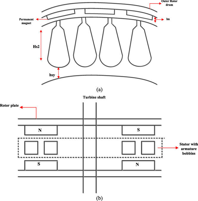
Configuration of permanent magnet generators (a) Outer Rotor RFPMG. (b) Coreless AFPMG.
As mentioned in the literature, the outer rotor RFPMG is better than inner rotor RFPMG in various aspects. However, certain drawbacks encountered in outer rotor RFPMG are mitigated through the axial flux machine. Even though the slot less (coreless) AFPMG has low magnetic flux than slotted (core) AFPMG, it has the advantages such as compact, high power density, natural cooling, less cogging torque, cheaper construction cost, higher moment values, sinusoidal phase waveforms, less material consumption, less core loss and weight, higher torque to weight ratio, higher power to weight ratio, adjustable air gap, less noise and vibrations. Apart, the double sided AFPMG offers the benefits such as better mechanical balance, double air gap and better cooling over the single sided AFPMG. In this work, the double sided coreless AFPMG has been modeled and the performance has been compared with RFPMG through finite element methods (FEM).
The performance parameters are flux linkage, flux density, induced emf, stator current, moving torque, cogging torque, material consumption and efficiency. Figure 1 shows the various components and its arrangement of outer rotor RFPMG and double sided coreless AFPMG.
Generator rating
In RFPMG the permanent magnets are placed in the outer periphery of the machine which gives the radial flux whereas in the AFPMG permanents magnets are placed in the back iron of the rotors such that the magnetic flux are in axial direction to the stator.
The below Table 1 shows the generator rating of RFPMG and AFPMG.

Slot dimensions of RFPMG.
Stator slot dimensions of RFPMG
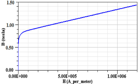
B-H curve of NdFeb.
The remaining part of the article is organized as follows, Section 2 of the article describes the design aspects of generator and Section 3 describes the electromagnetic analysis. The performance evaluation is given in Section 4 and the conclusion given in Section 5.
Design parameters of RFPMG and AFPMG
The permanent magnet generators must be properly designed to ensure the desired performance. The main dimensions of the generators should be calculated perfectly along with the number of slots and its dimensions, number of poles & coils, speed of the machine and the required output voltage and then the FEM analysis can be carried out using these calculated parameters. In this section calculation of design parameters have been done for 3 phase, 3 kW, 415 V, 50 Hz, RFPMG and AFPMG. The RFPMG is an outer rotor type and AFPMG is a coreless double rotor (outer rotor) type.
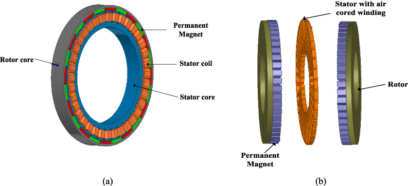
Structural overview of generators (a) RFPMG (b) AFPMG.
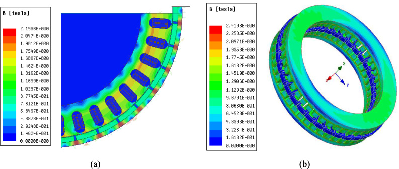
Magnetic flux distribution (a) RFPMG (b) AFPMG.
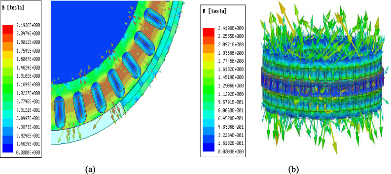
Vector direction of magnetic flux distribution (a) RFPMG (b) AFPMG.
The equations ((1))–((2)) shows the outer diameter of the RFPMG & AFPMG respectively [22]
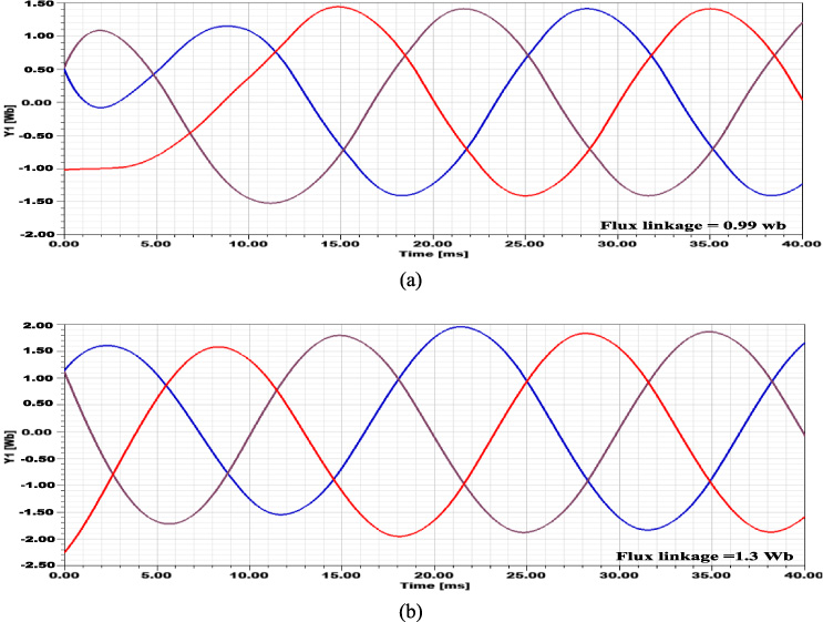
Flux linkage (a) RFPMG (b) AFPMG.
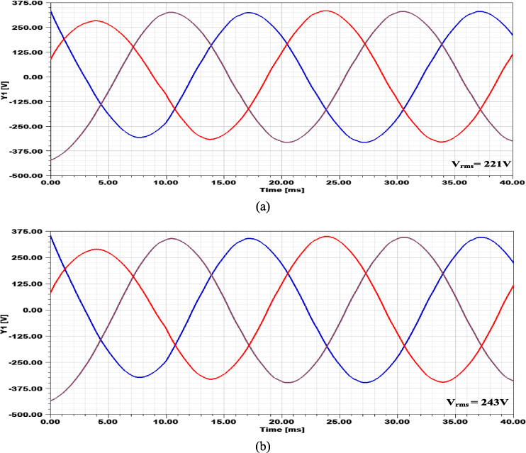
The induced emf at no load condition (a) RFPMG at 250 rpm (b) AFPMG at 125 rpm.
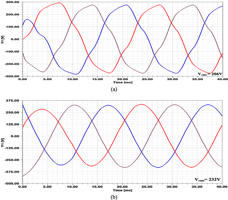
The induced emf at rated load condition (a) RFPMG at 250 rpm (b) AFPMG at 125 rpm.
By substituting the rated power, outer diameter and speed, the length of the AFPMG can be found [23].

The stator current at rated load condition (a) RFPMG at 250 rpm. (b) AFPMG at 125 rpm.

Moving torque (a) RFPMG at 250 rpm (b) AFPMG at 125 rpm.
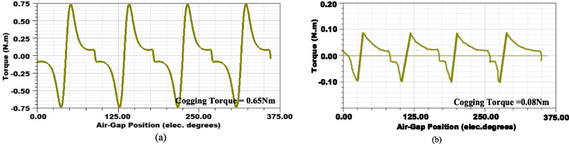
Cogging torque (a) RFPMG at 250 rpm (b) AFPMG at 125 rpm.
The rotor inner diameter and the stator outer diameter of RFPMG can be calculated using the below given Eqs ((5)) and ((6)).
Since the AFPMG has coreless stator, the number of slots need to be calculated only for RFPMG.
The number of slots of RFPMG is calculated using the equation ((7))
Figure 2 shows the slot dimensions of RFPMG.

Copper loss (a) RFPMG at 250 rpm (b) AFPMG at 125 rpm.
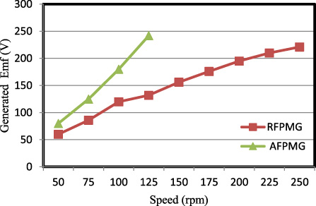
Speed vs Output voltage.

Speed vs Output power.

Load current vs Phase voltage.
The slot dimensions of RFPMG have been chosen based on rated voltage and the selected values are given in Table 2.
The equation ((8)) shows the inner diameter of the stator of RFPMG. By substituting the values given in Table 2 in Eq. ((8)), the inner diameter can be calculated
The inner diameter of AFPMG can be calculated using the Eq. ((9)) [24].
Due to axial flux configuration of AFPMG, the outer and inner diameter of stator and rotor will remain same.
The neodymium-iron-boron magnet (NdFeb) is chosen as permanent magnet in both the generators due to its high magnetic field, high coercitivity and high power to weight ratio. The B-H curve of the magnet is shown in Fig. 3.
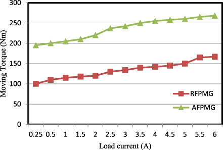
Load current vs Moving torque.
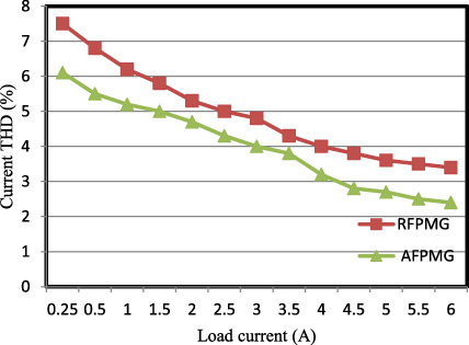
Load current vs Current THD.

Load current vs Voltage THD.
The trapezoidal shape of magnet is used because of high magnetic flux density over conventional circular magnet [25]. Thus it ultimately improves the performance of the permanent magnet generator over other types which uses the conventional shape of the magnets.
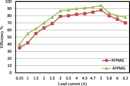
Load current vs Efficiency.
Material consumption of RFPMG and AFPMG
Comparison of output parameters between RFPMG and AFPMG
The expression for flux linkage of RFPMG and AFPMG is given in ((10)) and ((11)) respectively.
The generated emf of RFPMG & AFPMG is given in Eqs ((12)) and ((13)) respectively.
The air gap of the machine is taken as 1 mm. Double layer concentrated windings are used in the stator of RFPMG and AFPMG. Table 3 shows the design parameters of the generators.
The generators has been modeled using the parameter’s values given in Table 3 through the Maxwell software (electromagnetic suite 17.2) and their structural over view is shown in Fig. 4. Here both RFPMG and AFPMG are designed for the same power rating of 3 kW and hence no of slots and no of pole pairs of both the machines are different to satisfy the associated power rating. Apart in RFPMG, speed of the machine is limited since large no of poles results in increased core size of the machine and thus increases the weight of the machine. But in the case of AFPMG, the limitation of number of poles has been eliminated through the proposed coreless structure.
The performance of the generators can be analyzed through the finite element method. In this section, an outer rotor radial flux PMG and double-sided axial flux PMG are simulated through the modeled generators as given in Section 2. The performance of both the machines is analyzed by using either two dimensional (2D) or three-dimensional (3D) model to get the results. The performance parameters such as flux linkage, flux density, induced emf, stator current and torque has been presented in this section. The simulation results have been taken at different speed of generators from no load to full load. Figure 5 shows the magnetic flux distribution of RFPMG and AFPMG.
From Fig. 5, it is observed that the various range of flux linkage exist between the stator and rotor part of the PMG’s. The maximum flux linkage in RFPMG is 1.02 Wb whereas it is 1.32 Wb in AFPMG. The flux linkage in AFPMG has been improved through the usage of NdFeb48 magnetic material which exhibits better B-H characteristics than NdFeb30 as well as double-sided rotor structure. The vector direction of the magnetic flux distribution of RFPMG and AFPMG is shown in Fig. 6.
From Fig. 6, it is understood that the vector direction of the magnetic flux is radial in RFPMG and axial in AFPMG.
Figure 7 shows the flux linkage in the generator.
The maximum flux linkage in the airgap of AFPMG is more i.e 1.3 Wb/m2 than RFPMG i.e 0.99 Wb/m2. These simulated values of flux linkages matched with the calculated values from the expression (10) and (11) respectively.The maximum flux linkage of AFPMG is due to the shorter axial path of magnetic flux whereas in RFPMG the magnetic flux path is circular and there will be losses in each portion of that path.The induced emf of RFPMG and AFPMG at no load and rated load conditions at their rated speed is shown in Figs 8–9 respectively.
The output voltage of the RFPMG and AFPMG are 221 V and 243 V respectively at no load condition whereas at rated load condition the output voltage is 206 V and 232 V respectively. In both the load conditions, the voltage magnitude is higher in AFPMG. Even though the whole coiled winding is used in both the generators, the quantum part of the winding is inactive in RFPMG due tothe coil overhang. It affects the induced emf in its stator coil. However the coil overhang does not exist in AFPMG due to its unique structure. Also the absence of the coil overhang improves the nature of sinusoidal emf. Figure 10 shows the 3 phase current waveform of RFPMG and AFPMG respectively at rated load conditions.
From Fig. 10, it is observed that the AFPMG generates the current of 5.65 A whereas RFPMG current generation is 3.53 A. The capability of current generation of AFPMG is more due to its high generated emf. The Figs 11–12 shows the moving torque and cogging of RFPMG and AFPMG respectively.
From Figs 11–12, it is understood that the moving torque of AFPMG is high i.e 265 Nm than RFPMG. Both AFPMG and RFPMG produce the ripples in the torque. This is due to placing permanent magnets in the surface area of the generators. The cogging torque produced in AFPMG is minimum than RFPMG. This is due to the very minimum action of magnetic locking between the stator and rotor because of its coreless structure [26]. In generators copper loss are the more dominating phenomenon than iron loss [27] and hence the copper loss of generators has been analyzed here. Figure 13 shows the copper loss of RFPMG and AFPMG.
From Fig. 13 the copper loss (or solid loss) of RFPMG is 230 W whereas AFPMG is 190 W. Even though the current generated by the AFPMG is more, its winding length is comparatively very less due to which the resistance of the winding is drastically reduces and it contribute for reducing the copper loss (I2R). Apart, the concentrated winding is adopted in the stator of AFPMG and it avoids the coil overhang issue which is one of the cause for copper loss. The copper losses are increased in the generators when the different frequencies of harmonic current flows through the winding since the AFPMG offers less THD the harmonic current reduces due to which copper losses reduces. Hence it is concluded that less material consumption, concentrated type of windings and less THD are contributed for achieving less copper loss in AFPMG.
Performance evaluation of RFPMG &AFPMG
The performance evaluation of RFPMG and AFPMG has been carried out in various aspects such as induced emf, frequency, output power, THD and losses in order to exhibit the best generator for low speed wind turbine applications. The generator’s induced emf is varying with respect to the wind turbine speed. Figure 14 shows the speed vs induced voltage curve of RFPMG and AFPMG.
From Fig. 14, it is understood that the phase voltages of the generator’s keep on increasing with respect to the speed. The RFPMG gives the rated phase voltage at 250 rpm whereas the rated phase voltage is attained at 125 rpm in AFPMG. The attainment of rated voltage with minimum speed in AFPMG is due to possibility of accommodating of more number of permanent magnets in AFPMG [28] and low magnetic saturation effect rather than RFPMG. In RFPMG [29], the rated voltage can be achieved in less speed but it requires the more number of permanent magnet and ultimately it increase the total weight of the generator. It minimizes the torque to weight ratio of the machine. The rotor weight of AFPMG gets increased by the permanent magnets [30]. However it doesn’t contribute for total weight increment of the machine due to its coreless structure. The speed vs output power is shown in Fig. 15.
The speed vs output power curve is obtained by varying the speed at the rated load of 3 kW. Figure 16 shows the output voltage variation corresponding to the different loading conditions.
From Fig. 16, it is observed that voltage drop becoming more in RFPMG than AFPMG during minimum to maximum loading condition. Output voltage of RFPMG is dropped from 225 V to 160 V. In AFPMG it is from 245 V to 223 V. The moving torque value of generators for different loading conditions is shown in Fig. 17.
AFPMG offers better moving torque than RFPMG due to its more current generation capability as shown in Fig. 17. Figures 18 and 19 shows the THD versus load current of RFPMG and AFPMG respectively.
In both the generators, the current THD (I THD) is changing drastically with respect to load current. The current THD is indirectly proportional to load current due to which it decreases when load current increases as shown in Fig. 18. But the voltage THD (V THD) slightly reduces while load current increases since the voltage THD is the independent factor of load current. The voltage and current THD of AFPMG is less due to its improved sinusoidal wave shape. At rated load, in AFPMG the V THD is 3.5% and I THD is 2.8%. Figure 20 shows the efficiency of the generators for different loading conditions.
From Fig. 20, it is observed that efficiency of AFPMG is higher than the RFPMG since it has less copper loss as well as no core loss. Table 4 shows the details of material consumption of the generators.
The armature copper density and Permanent magnet density of the both generators are same as observed in Table 4. Since the double the amount of Permanent magnet’s used in AFPMG, it’s weight is more. However, the total material consumption of AFPMG is only 47.17 % of RFPMG, since the AFPMG doesn’t use the core for its stator and rotor. Also the cost of AFPMG is less due to active material consumption and less manufacturing cost than RFPMG. Table 5 shows the comparison of RFPMG and AFPMG at rated load condition.
From Table 5, it is observed that the AFPMG has the higher torque, less THD, loss and higher efficiency. Also, the AFPMG offers rated voltage and power at minimum speed. The above said qualities of AFPMG becoming more suitable for low speed wind turbine applications.
Conclusion
Based on the machine design calculation the simulation model of the RFPMG and AFPMG is carried out in ANSYS Maxwell software. The performance evaluation has been done on 3 kW RFPMG and AFPMG. From the simulation results, it has been concluded that AFPMG offers better flux linkage, flux density, high induced emf and current, high moving torque, low cogging torque, less volume, less loss and higher efficiency. These desirable characteristics of AFPMG make it more suitable for low speed wind turbine applications.