
Abstract
The main aim of this work is to determine the optimal shape design of a class of Interior Permanent-Magnet (IPM) motors for electric vehicles (EV), by means of many-objective optimisation which is an emerging area in the automated optimal design. As the case study, a 3-phase, 4-pole single-barrier IPM motor is modelled by means of using finite-element analysis. The goal is to optimise the motor’s performance in terms of a number of design criteria such as the power losses, running torque, torque ripple and material costs, by varying size and position of the permanent magnet and flux barriers.
Keywords
Introduction
In this paper, strategies for solving many-objective optimisation problems are studied under the framework of a class of motors with applications in electric vehicles. In particular, a shape design of an Interior Permanent Magnet (IPM) motor is considered. Due to their highly salient rotor structure and strong reluctance torque component, IPM motors are commonly characterised by high torque density, high power density and a wide speed range for during constant power operation and high efficiency. Therefore, IPM machines have been considered a good candidate for high-performance traction applications.
Extending the constant-power speed range (CPSR) for an EV motor is the key to operating at a wide speed range [1]. In IPM machines, because the permanent magnets are located inside the rotor, the field is directly short-circuited through the rotor iron core that leads to magnetic flux leakage. Therefore, the geometry of the permanent magnet significantly impacts the motor performances, e.g., the cogging torque and the iron losses as well as the constant-power speed range.
In order to improve the performances of this kind of motors, many requirements can be demanded. In particular, a lightweight, compact and efficient motor in terms of low iron loss, high running torque but low ripple torque, are only some of the desired design requirements. Hence, the design of such motors is naturally formulated as a many-objective optimisation problem that can be eventually solved by means of an objective-reduction strategy [2]. An attempt to solve the problem following a different approach is developed in this paper.
Wind-Driven Optimisation (WDO) is a population-based heuristic global optimiser inspired by the motion of air in the Earth’s atmosphere, where the wind attempts to balance, and it can be effective in solving multidimensional numerical optimisation problems [3].
In the literature, wind-driven optimisation has been recently used for several engineering problems such as antennas, solar photovoltaic systems, tracking applications and magnetic devices [4–10]. For instance, a hybrid invasive weed optimisation and wind-driven optimisation (IWO/WDO) is proposed in [6] to minimise the interference effect of a uniformly excited linear sparse array by position control. Interference minimisation is implemented in such a way that the linear sparse array pattern exhibits minimum side-lobe level (SLL) with a constraint on beam width. In [7] WDO is used to design a thinned array with a minimum number of transducers for multi-beam imaging sonar. In turn, WDO is used in [8] as a tool for parameter estimation of a 12p-DDM of solar PV. Similarly, WDO scheme was shown to be a useful tool in [9] for the design of high impedance surfaces with ultra-small interwoven unit cells. Likewise, WDO has been implemented for superconducting magnetic energy storage (SMES) device with eight free design parameters to obtain the desired stored energy with minimal stray fields [10]. In all the aforementioned works, a single objective function has been considered in the WDO algorithm.
The WDO algorithm, which was recently extended to the multi-objective case [11], is applied in the design of a switched reluctance motor [12]. In the paper, more than two objectives have been targeted for optimising simultaneously three objective functions, and subsequently extending the number of objectives to four. For each couple of objectives, the simulation results are compared with the Pareto ranked bi-objective optimisation in order to assess the effectiveness of the proposed many-objective WDO algorithm.
The interior permanent magnet motor
The structure of the three-phase targeted IPM motor is shown in Fig. 1. The motor sizing parameters and specifications are listed accordingly in Table 1.
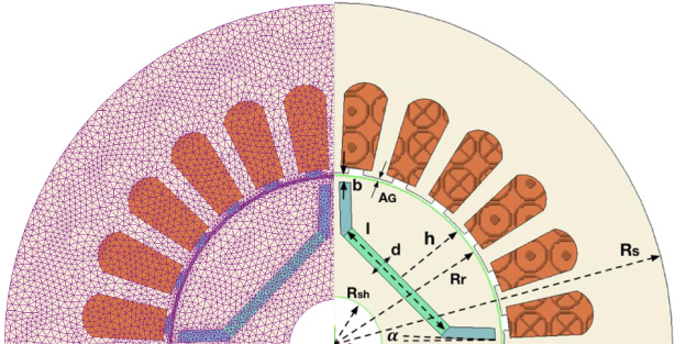
The three-phase IPM motor geometry and 2D mesh.
The IPM sizing
The motor is a 4-pole 24-slot brushless DC motor with round stator type and a rotor of IPM type with the rated power about 500 W. The external radius is 56 mm, and the permanent magnets are made of Neodymium Iron Boron (NdFeB) material while the rotor and stator are made of laminated steel. There are eight coils per each of the three phases, supplied by a sinusoidal current of 3 A that lag each other by 120°. A finite-element model of the motor has been developed; its 2D mesh is shown in Fig. 1. The field solution at 0° and 15° rotor positions are shown in Figs 2(a) and 2(b), respectively.
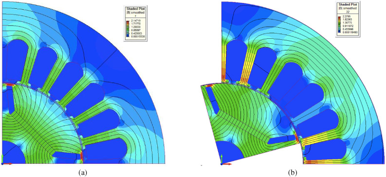
(a) The field solution at 0° rotor position. (b) The field solution at 15° rotor position.
In order to decrease the number of finite element analysis and the simulation calculation time, 1∕4 of the model is analysed taking advantage of the motor symmetry. The rotation of the rotor along the midline of the air gap has been simulated in discrete steps of 1° over the 90° polar pitch to determine the running torque, cogging (ripple) torque and iron losses. In order to ensure a good solution, different maximum mesh element sizes have been assigned to the different parts (0.5 mm in the rotor and permanent magnets and 1 mm in the stator). The mesh is refined with the maximum element size of 0.25 mm in the air gap regions for accurate machine analysis and calculations.
The plots of the iron loss, running torque and cogging torque versus rotor position over 32 degrees for the prototype are shown in Figs 3(a), 3(b) and 3(c).

(a) The cogging torque, (b) The running torque, (c) The iron loss, versus rotor position over 32 degrees for the prototype.
The cogging torque in the IPM motor is generated due to reluctances between the rotor and the stator teeth. The torque and power loss are derived based on the following equations.
Because the torque and iron losses in the motor are dependent on the rotor position, in order to calculate f 1, f 2 and f 3, several finite element solutions (FEA) have to be determined.
WDO is an optimisation algorithm designed for solving real-valued numerical problems. Similarly, in optimisation, the design points are moved from high-gradient to low-gradient positions. It is similar to other particle-based optimisation such as particle swarm optimisation (PSO) in updating the position and velocity; however, WDO has a high global searching ability and fast convergence due to its actual physical meanings in updating the equations. In the WDO algorithm, the air particles’ velocities and positions will change during each iteration to explore the new searching space. Therefore, the variable for velocity can be expressed as,
The following four terms characterise the right-hand side of Eq. (4):
The inertial term, where a is the fixed coefficient of friction whose value usually ranges between 0.8 and 0.9. The gravitational-like term, where g is the acceleration of gravity, ranging from 0.6 to 0.7 and is responsible for pulling towards the current particle position towards the centre of the gravity. The pressure-gradient, where x
∗ represents the optimal positions of the air particles in regard to the lowest pressure found in the previous iterations; 𝛽 is equal to R × T in which R is the universal gas constant, while T denotes the temperature. 𝛽 ranges in the interval of [1.0, 2.0]. The Coriolis-like acceleration term; which mimics the Coriolis force that provides the influence of air particles’ velocity by the orthogonal velocity of another, consequently enhancing the robustness of the algorithm. The constant c usually ranges in the interval of [0.05, 3.6] [12,14].
The position of the ith air parcel at iteration k +1 is then updated as in Eq. (5).
Moreover, to ensure that air not being stuck at or jumping out of the searching border, the boundaries should be set up according to the specific situation while their updating velocities also change in a certain range as follows:

The flowchart of the M-WDO pseudocode.
In the multi-objective version of the WDO, a new definition of pressure employing a generalised fitness is used. The generalised fitness takes into account simultaneously two or more objective functions by exploiting the concept of non-dominated ranking of solutions in the objective space. At the k-th iteration, air parcels are ordered according to two criteria: first, they are subdivided in locally non-dominated sub-fronts which, in turn, are ranked from the first to the last. Next, air parcels are ranked within the sub-front they belong to, taking into account their crowding distance; in fact, crowded air parcels are less preferred than air parcels which are regularly spaced. At the end of a step-by-step procedure, a fitness value is assigned to each air parcel; this makes it possible to sort the parcel swarm from the best air parcel to the worst one. In particular, j in Eq. (4) is the rank of the i-th solution based on the generalised fitness, while x ∗ is a non-dominated solution randomly selected out of the current Pareto front.
The design variables considered for the shape design are g = [d, l, h, b, 𝛼] in which, d represents for width, l for length and h for the position of the magnets (magnet-to-airgap radial distance), respectively. The thickness of the bridge (width of bridge between the flux barriers and air-gap) denotes as b and its orientation angle 𝛼, which is the angle of barrier outer-end to rotor centre (see Fig. 5).

The design variables.
The objective functions are the following:
The problem constraints imposing the geometrical limits and space boundaries are as follows:
The prototype IPM motor has initial width, length and position of the magnet of 3 mm, 20 mm and 12 mm, respectively. The bridge width is 1 mm, and the angle is 2 degrees.
In this work, the many-objective optimisation problem has been solved using a multi-objective wind driven optimisation (WDO) based on Pareto-optimal solutions [4]. WDO has been implemented by coupling a numerical computing environment [15] with a commercial Finite Element software [16]. As a consequence of rotor rotation, 86 non-linear field solutions were completed for a given device geometry. The computation of each non-linear field solution lasts about 3 s on a computer equipped with a CPU working at 3.6 GHz and with 16 GB of RAM. For each optimisation, 100 iterations were run with 15 air parcels, and hence 1,500 solutions are evaluated for each optimisation run and the WDO optimisation parameters are reported in Table 2.
WDO parameters
3D optimisation results (case A).

3D optimisation results (case B).
The simulation has been considered for 3D optimisation problem that results in four simulation cases, namely case A, B, C and D. Case A is referred to a 3D objective space where T r is the non-controlled objective and the rest of the objectives are controlled. Accordingly, M, P and T c are the non-controlled objectives in case B, case C and case D, respectively. The 4D optimisation, all four objective functions are considered.
WDO solutions in 3D objective space
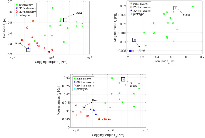
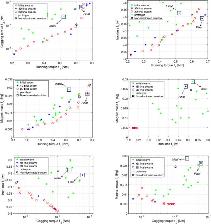
The objective space in many-objective optimisation handles more than two objective functions which are in conflict. In particular, the developed WDO algorithm for this work is considered for three and four objective functions which result in 3D and 4D objective spaces, respectively. The objective space solutions for 3D are shown in Fig. 6 to Fig. 9 while Fig. 10 illustrates the 4D objective space.
3D optimisation results (case C).

3D optimisation results (case D).
4D optimisation results.
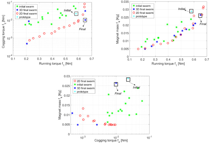
WDO solutions in 4D objective space
Furthermore, the solutions are shown in the 2D projections of the objective space. In each projected space resulted from employing the WDO methodology, the Pareto front which obtained by means of 2D optimisation is considered as the reference (red circles). The latter is compared with the non-dominated solutions obtained by 3D (or 4D) cases.
Apparently, in some of the figures, there are numbers of non-dominated solutions in the bi-objective Pareto optimal algorithm that have been dominated by 3D or 4D solutions. The earlier mentioned remark can be explained by considering the nature of the problem which aims at improvement of more than two objective functions while it has not been taken into account in bi-objective optimisation. Therefore, there are solutions to the device dimensions in the search space which can satisfy several objectives at the same time.
The set of non-dominated solutions on the Pareto front (marked by red circles and blue stars) are examples of best compromise solutions between conflicting design criteria, i.e., the running torque, the cogging torque, loss and magnet mass [17,18]. In order to show the specific improvements, the comparison of one selected solution for each 3D and 4D solutions with the initial design (prototype) are reported in Tables 3 and 4, respectively.
It can be noted that in the 2D and 3D cases the optimised solution corresponds to the simultaneous improvement of the relevant objective functions; in contrast, in the 4D case, the optimised solution improves three out of four objective functions, while deteriorates the cogging torque. Moreover, a non-dominated solution has been found during the 4D optimisation which improves all the four objective functions with respect to the initial point (prototype), although the algorithm did not converge to it as the final solution. This could be due to an insufficient number of iterations in the optimisation process. Therefore, during the optimisation process, it has been found at least one device which corresponds to a device globally better than the initial one for all the four objective functions.
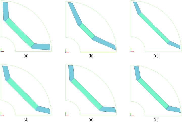
The comparison of the PM geometry related to the final solutions, (a) The prototype, (b) Final solution A in 3D space, (c) Final solution B in 3D space, (d) Final solution C in 3D space, (e) Final solution D in 3D space, (f) Final solution in 4D space.
For the sake of comparison, the PM physical size and geometry in each 3D and 4D objective space are depicted in Fig. 11.
The wind-driven optimisation algorithm was generalised to the many-objective case. It was applied to obtain the Pareto front of shape design problems characterised by more than two conflicting criteria. The families of non-dominated solution trade-offs between the running and cogging torques, iron loss and the magnet mass of an IPM were successfully identified. The increasing dimensionality of the objective space (OS) limits the possibility of improving the prototype solution in the Pareto sense.