
Abstract
An experimental approach is proposed to study the influence of the punching on the magnetic behavior of a stator core strips. Specimens of a non-oriented M330-A35 punched lamination sheet are picked up from a real manufacturing process. The proposed approach is based on the use of two types of specimens; one is a closed magnetic circuit while the second one is split into two parts. Magnetic measurements are performed on both types and compared with those made on specimens cut by WEDM which has a lower impact on the magnetic behavior. The specific purpose of this paper is to investigate the impact of punching in presence of an air gap that exists in electrical machines between rotor and stator. Therefore a dedicated device, optimized by FEM simulations, is developed in order to account accurately the air gap.
Introduction
The punching process, based on a shearing phenomenon with a precisely shaped tool, is a very fast cutting process well adapted for mass production. However, as any manufacturing process, it affects the material properties and leads to magnetic behavior degradation [1,2]. Globally, it leads to a reduction of the magnetic permeability and an increase of the iron losses. Several studies have investigated the identification of the impacted zone with different methods. The results show that punching could impact the material, depending on the cutting parameters, up to 1.6 mm from the cut edge [3].
As a first approach, existing studies address the impact of punching on the magnetic behavior considering normalized characterization devices. Nevertheless, the extrapolation of the results to real application is not necessarily straightforward, since the effect of punching strongly depends on process parameters [4,5] as well as the magnetic flux path with regard to the cut edge. This is particularly the case of the magnetic flux flowing through the air gap between the stator and the rotor that plays an important role on the electrical machine performances.
In this paper, we propose an approach to characterize samples, collected from a slinky stators manufacturing process, under conditions which are very close to the real operating ones of the electrical machine (similar flux path, air gap…). This approach enables to estimate the effect of punching on the magnetic behavior of the stator for the considered electrical machine.
Experimental conditions
Sample geometry
Two types of punched samples are considered: the first type (denoted C_sample for Closed sample) represents a closed magnetic path (without airgap), the second one (denoted O_sample for Open sample) consists of two parts, which represent the upper and the lower parts of the first sample cut in the middle. In fact, the slinky stator yoke fabrication is performed in several steps that allow extracting these two types of samples. 1 summarizes the characteristics of the studied material.
Chemical composition and informations about M330-35A
Chemical composition and informations about M330-35A
Each characterized sample consists of 5 stacked laminations of the same type (with or without airgap). In order to estimate the impact of punching, the electromagnetic behavior of samples are compared with reference samples having the same geometry and extracted from the same lamination sheet. These reference samples are obtained from the Wire Electrical Discharge Machining (WEDM) cutting process. This process is well known for its precision and also its limited impact on the magnetic behavior [6]. Thus, the magnetic behavior of these samples will be considered as a reference in the following.
The same magnetic measurement method is applied on both sample types obtained by punching and WEDM. Primary and secondary windings are placed around teeth as shown in Fig. 1. The considered samples form a closed magnetic flux path, but with a non-constant cross-section. Thus, the estimation of the magnetic flux density is not straightforward as the section of the flux path is not constant. Therefore, it is chosen to consider the evolution of the magnetic flux and the imposed magnetomotive force (Um) in order to evaluate the impact of the process. In addition, for a more convenient comparison, we will consider in some results the average magnetic flux density calculated from the average section of the magnetic circuit.
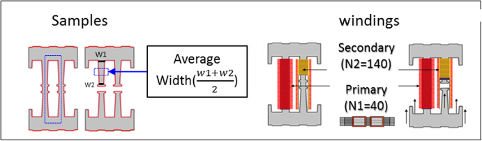
Extracted samples and the schematic of the teeth magnetic characterization.
Measurements have been performed with sine waveforms in the frequency range [10 Hz–1.5 kHz] with an average flux density from ∼0.2 to ∼1.5 T for the C_samples and ∼0.2 to ∼1.2 T for the O_samples.
In order to investigate accurately the impact of punching on the magnetic behavior in the presence of air gap, a specific characterization device has been developed (Fig. 2). It enables to control the airgap between the two parts of the O_ sample within a tolerance of a μm. We have to note that the airgap between the rotor and the stator of the considered machine is about 300 μm. During measurements, one part is clamped and the position of the second part is adjusted via a micrometric screw. The displacement of the moving part is measured directly using an LVDT (Linear Variable Differential Transformer) displacement sensor according to Abbe principle [7].
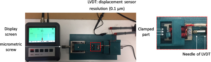
The experimental device for open samples.
When both parts are in contact, the airgap is considered null. However, the contact between surfaces is not perfect. In fact, the cut specimens for both techniques, WEDM and punching, are stacked manually by sticking the sheets together. Therefore, the surface of the stack facing the air gap is not perfectly plane. Some profile measurements, using an optical roughness meter, has been performed on the O_sample parts. The measurements show that deviation between the sheets could reach 50 μm for WEDM samples and 100 μm for the punched ones.
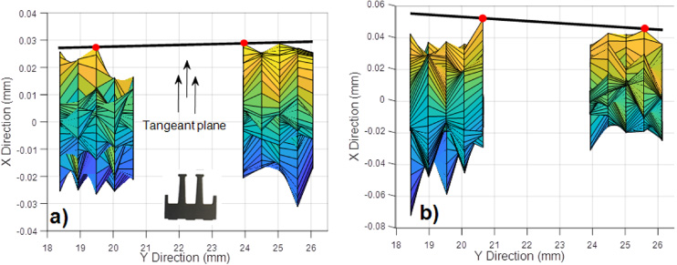
(a) The profile of WEDM sample, (b) The profile of the Punched sample.
In order to be more accurate, an effective measurement strategy was set up. WEDM and Punched samples are placed as they are during the magnetic characterization, and 3D measurements are realized using a ZEISS Coordinate-measuring machine (CMM) (Fig. 3). The parasitic air gap between parts is calculated as follows:
We obtain two reference plans corresponding to both facing parts using the least square method. The deviation of points from the reference plans is calculated. Summing the deviations of the two parts points. Define a plane perpendicular on (xy) and tangent on the sum of deviations using a constrained least square algorithm. Calculate the difference between the plans and deviation points.
In order to evaluate the impact of the effect of the imperfections of the stacking (parasitic air gap) on our measurements, the problem is simulated using a 3D FEM model. Scattered points corresponding to each sample are imported into a computer-aided design software (CAD) to take into account the misalignment of sheets (Fig. 4). Geometries including parasitic air gap are simulated with ANSYS (Maxwell). The properties of the raw material (before being processed) have been measured using the Single Sheet Tester (SST ‘50 × 200’ mm2).
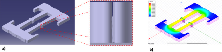
The CAD geometry taking account the parasitic airgap corresponding to the punched sample, (b) The FEM simulation on the punched sample.
The SST sample width is high enough, thus the impact of cutting on the magnetic behavior is considered negligible. The measured characteristics are considered those for raw material and are imported in a finite element model. The simulation does not take into account the effect of punching or WEDM. The purpose is to quantify the maximal error due to the geometry difference.
We have simulated for the two parasitic air gaps (WEDM and punched) the evolution of the magnetic flux in function of the current in the primary coil. In Fig. 5, we present the evolution of the generated flux for different electrical current levels imposed in the primary winding at 50 Hz. We notice that the generated flux in WEDM sample is higher than the punched ones due to the fact of surface quality. Simulated results show that the highest difference peak is around 13% of the generated flux. As far as we are closer to the saturation level the difference will decrease and will be lower than 0.5%. After quantifying the impact of the parasitic airgap, we can now focus on the effect of the punching.
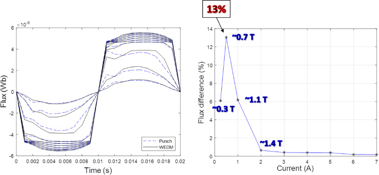
The impact of parasitic air gap on the magnetic behavior.
In Fig. 6, we present the hysteresis loops (Um) corresponding to the single core samples at 50 Hz, Punch_C for punched samples and WEDM_C for wire cut samples. It is clear that punching has a drastic effect on the magnetic properties, a significant degradation of the permeability is observed. Thus, extra magnetomotive force is needed in case of punched samples to reach the same magnetic flux level. For example, to reach 3.3 μWb in case of punching, we need 3 times more Um than in the WEDM case. Also, punching effect is well pronounced on the total losses. In Fig. 7 we present the total losses evolution with frequency for different magnetic flux magnitudes. The total losses difference between punched and WEDM samples decreases with frequency and reaches 90% at 50 Hz (at ∼1.1 T) while for higher frequencies the difference it is almost constant around 25% (at ∼1.1 T).
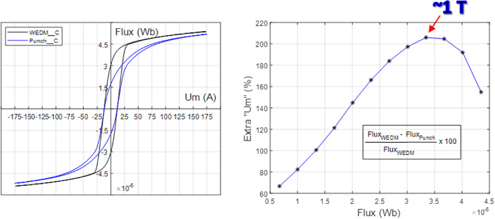
Impact of punching on hysteresis loop for closed samples.
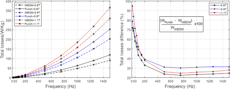
Impact of punching on total losses for closed samples.
This phenomenon can be explained by the fact that punching affects mainly the hysteresis behavior related to the quasi-static losses. Regarding the classical eddy current losses, they are expected to be similar, as the electrical conductivity is mainly defined by the material composition. These dynamic losses become more and more predominant with increasing frequency, total losses tend to be closer between both cases.
Magnetic measurements are performed on O_samples for different positions of the moving part (0–300 μm with 0 when parts are in contact). The Fig. 8a presents the hysteresis loops 𝛷 (Um) corresponding to the O_samples when they are in contact (parasitic airgap exist) at 50 Hz. We can notice that the magnetic behaviors of the O_samples worsen in comparison with C_samples (Fig. 6) due to the parasitic air gap (Fig. 3). Nevertheless, the impact of punching is clearly emphasized when compared with the WEDM sample. In order to quantify this impact, a procedure to separate the effect of the cutting technique from the effect of parasitic air gap is described in the following.
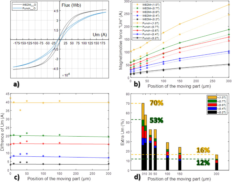
Impact of punching on magnetic behavior for open samples.
The Fig. 8b represents the evolution of the required magnetomotive force Um to reach different magnetic flux levels, in function of the position of the moving part. Figure 8c represents the difference between the magnetomotive forces required with punched and the WEDM samples required to reach a given magnetic flux. We can notice that this difference remains almost constant for different air gap values. In Fig. 8d the extra Um for punched samples in comparison to the WEDM ones are plotted for different magnetic flux density magnitudes:
We notice that, the global impact of punching decreases as the position of the moving part increases and it could reach 16% at about ∼1 T. This result could be expected because a higher Um is needed to magnetize the air gap region in order to impose the same magnetic flux in the samples, as the position of the moving part increases. We can see that the needed magnetomotive force Um, to magnetize the ferromagnetic circuit in presence of air gap is not negligible versus the ones in contact (postion 0) (Fig. 8b). Moreover, there is a significant difference of behavior between the samples obtained by punching and WEDM showing that the process has an impact that should be considered (Fig. 8c). For example for ∼1 T, if we take into account the maximum effect of the parasitic air gap (13%, Fig. 5), the difference of Um at position 0, in Fig. 8d, becomes 64% instead of 70% (2). At 300 μm the difference will be around 14.5% instead of 16%.
This paper presents an approach for studying and quantifying the effect of punching on a specific stator strips geometry. Magnetic measurements were performed directly on samples realized from punched lamination sheets, which are picked up from a real production line. In order to emphasize the effect of punching on the generated magnetic flux taking into account the gap between the rotor and the stator, a specific device allowing to control the air gap has been developed. Results showed that in presence of ∼300 μm air gap at least 14.5% of additional current is needed in order to reach the same magnetic flux level in comparison with the WEDM cutting technique which is known to have a low impact on the magnetic behavior. Finally, this study emphasizes that it is worthy to investigate more deeply the impact of the punching process in order to improve the efficiency of the electrical machines.