
Abstract
The static B-H relationship is a very important parameter, used in the characterization of magnetic materials. In the paper is presented a novel laboratory equipment that has an “8” figure shaped magnetic circuit, which is made from a negligible hysteresis soft alloy. The experimental set-up consists of two DC coils, in which the currents i 1 and i 2 are set, to obtain a null value of the magnetic flux in the median yoke that has an “O” shaped figure, with two AC coils. A stationary magnetic field inverse problem is solved, starting with a couple of DC currents (i 1, i 2) and a piecewise linear normal magnetization curve is computed. The nonlinearity of B-H relationship is treated by polarization fixed-point iterative method, while for each iteration the Green function is engaged. The static magnetization curve is compared, with the B-H relationship measured, using a high precision metrological device, on a toroidal sample made from the same material.
Keywords
Introduction
The static B-H relationship is important in electromagnetic field computation and electrical equipment performance.
The classical standard devices for the characterization of the magnetic materials are the Epstein frame [1,2], the Single Sheet Tester (SST) [3] and the hysteresis graph set-ups that are based on AC magnetizing current method [4]. They have a closed magnetic circuit, made from strips, arranged in a square configuration (Epstein), a double C laminated yoke with one strip inside (SST), or a toroidal sample with two coils, wounded around it (hysteresis graph). In the case of soft magnetic material characterization, these methods are regulated through IEC standards [2,3] and it has been recognized that the methods generate a systematic measurement uncertainty [4]. The soft magnetic materials behave as efficient magnetic flux multipliers and they are usually characterized as a function of the magnetizing frequency [5]. Standardized measuring equipment, when is used in AC conditions, presents the following disadvantages: specific sample shape, uniform magnetic field, time variable excitation current, which lead to the presence of the eddy currents in the tested material that generate supplementary energy losses [6–8]. These facts are not found in the case of DC measurements. If the B-H relationship is analyzed in a soft magnetic material, by using inductive methods, it can be considered that the constitutive law is determined in quasi-static conditions and the time-dependent phenomena are considered irrelevant. Some relaxation processes can be noticed, leading to time constants, comparable to the measurement time. Such an important effect is the Barkhausen noise that has a negative influence on the accuracy and reproducibility of the measuring results. The measurement of the magnetization curve is made in quasi-static conditions through two procedures, in which the magnetizing field strength is increased in a step-like way or by increasing the amplitude of the periodical magnetizing field with a reasonable slow frequency, in order to avoid eddy currents effects. In the first method, the B-H relationship is obtained through a point by point procedure and in the second approach the dependence is generated by connecting the maximum values of the symmetrical minor hysteresis loops.
In the paper an “in house” laboratory set-up and a measuring procedure are developed, to determine the B-H dependence, in magneto-static conditions. The set-up consists of an “8” shaped magnetic circuit with two DC current coils connected, so that the magnetic flux in the “O” shaped median yoke to have zero value. In order to detect the imposed zero value of magnetic flux it was used a MuMETAL (Fe15Ni80Mo5) piece (Vacuumschmelze GmbH), with 0.8 T saturation magnetic flux density and 0.55 × 10⁻⁶ Ωm electrical resistivity, which has two parallel-connected AC current coils.
Device and measuring procedure description
Usually, closed magnetic circuits are used as first option [5], to characterize soft magnetic materials, because if they are tested, through open magnetic circuits, the demagnetizing field could have a higher value than the effective field and the retrieval of the effective field leads to a measuring uncertainty.
The base configuration of the proposed device (Fig. 1) consists of an “8” shaped magnetic circuit, in which the columns and the horizontal yokes are made from an isotropic material with negligible remanence (1). Two coils (5, 6) are connected in such a way, that the magnetic flux 𝜑0 in the median yoke (2), may be cancelled. In order to reduce the influence of the technological air-gaps on the measurement, the junctions between the columns and yokes are greased with a ferro-fluid. The upper yoke has an air-gap (3). It has a benefic effect on the procedure stability. On the lower yoke the analyzed sample (4) can be inserted. The two DC coils are powered by BK Precision 9600 30V, 5A DC Power Sources.
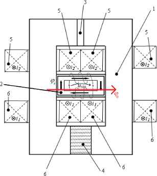
Measuring set-up description: 1 - magnetic circuit; 2 - “O” shaped median yoke; 3 - auxiliary air-gap; 4 - sample; 5 - DC coil 1; 6 - DC coil 2.
The method to determine the static B-H relationship is described as it follows: a given DC current value i 1 is supplied through the coil (6) and the current i 2 in the coil (5) is modified until the flux 𝜑0 is null. This operation is repeated, by increasing the value of i 1. Finally, a set of currents (i 1, i 2) are obtained and are used as input data in an inverse magnetic field problem.
The detection of the null magnetic flux is done through the “O” shaped piece, made from a soft magnetic material that has high relative magnetic permeability, which determines a high slope value of the B-H dependence, followed by a rapid decrease of the slope at the saturation point (Fig. 2).
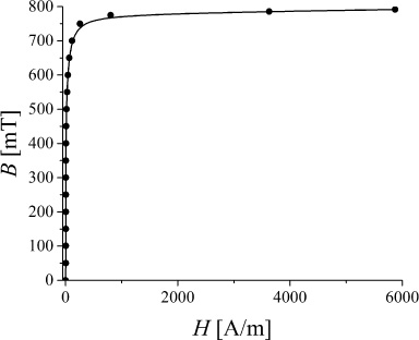
B-H relationship for the MuMETAL “O” shaped piece.
The “O” shaped piece coils are supplied by a 50 Hz AC variable power source and they generate a circular magnetic flux 𝜑 S in the “O” piece branches. When the sum between the two fluxes 𝜑0 and 𝜑 S that magnetizes the “O” shaped piece is above its saturation point, the value of the AC current is reduced.
At the beginning of measurement process, for i 1 = i 2 = 0, the magnitude of the sinusoidal voltage of the “O” coils, is set so that the value of magnetic flux density is immediately under the MuMETAL saturation point. Now, the AC current is almost sinusoidal and, for a small increase of the “O” coils’ voltage, AC current becomes non-sinusoidal. In the measuring procedure, it is not necessary that the “O” shaped piece magnetic characteristic to be known by the user. To observe the voltage and current waveforms on the AC coils, it is used a LeCroy WaveSurfer 422 Dual Channel Oscilloscope (channel C1 measures the current and channel C2 measures the voltage) and a shunt resistor (1 Ω).

Voltage (C2) and current (C1) variation in the AC coils for a non-null magnetic flux (i 1 = 70 mA, i 2 = 160 mA).
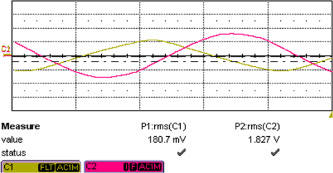
Voltage (C2) and current (C1) variation in the AC coils for a null magnetic flux (i 1 = 70 mA, i 2 = 210 mA).
Increasing the value of the DC currents (i 1, i 2) determines the “O” piece coil current to become non-sinusoidal (Fig. 3). In this case, when the median yoke magnetic flux is not zero, the “O” piece magnetic flux density is higher than the saturation value. The value of i 1 is kept constant and the value of i 2 is increased until the AC current becomes sinusoidal again (Fig. 4). At this point, the (i 1, i 2) currents are retained in order to compute the sample normal magnetization curve.
When the flux 𝜑0 is zero in the median yoke, the entire magnetic flux in the device magnetic core circulates through the inferior yoke, sample, columns, superior yoke and auxiliary air-gap and it should have almost the same value. In addition, the magnetic reluctance of the median yoke does not influence the magnetic field distribution. It was chosen the MuMETAL alloy, because it has a low remanence and a very strong nonlinearity [9]. The “O” shaped piece, was made of strips with 0.1 mm thickness, stacked together and cut through electro-erosion, to limit the influence of the mechanical stresses [10].
The proposed set-up does not have any kind of restrictions regarding the magnetic field uniformity, coils currents are constant, and the sample does not need to have a standard shape, although two plan parallel faces are necessary, to fit properly into the set-up magnetic circuit.
In the case of a cubic shaped sample, the B-H relationship may be obtained using a magnetic circuit model, where the magnetic flux 𝜑 [Wb] is function of the magnetomotive force u m [A]. A circuit diagram, using magnetic reluctances and magnetomotive forces can be associated to the laboratory set-up magnetic core (Fig. 5), where: R 1, R 3 and R core are the nonlinear reluctances of the yoke, R 2 is the nonlinear reluctance of the sample, R δ is the auxiliary air-gap reluctance, E 1 = Ni 1 and E 2 = Ni 2 are the magnetomotive forces of the two DC coils. When 𝜑0 is null through the median yoke, the other branches of the magnetic circuit have the same flux distribution 𝜑’.

The associated circuit diagram for the magnetic circuit of the device.
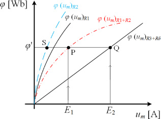
Graphical dependencies 𝜑 (u m ) used to determine the nonlinear characteristics of the magnetic circuit reluctances.
The dependence 𝜑(u m ) is approximated, supposing that the cross-sectional area S and the length of R 1 and R 3 are known. The 𝜑(u m ) dependence of R δ, is linear.
The reluctances R 3 and R δ are connected in series, so 𝜑(u m ) R 3+R δ can be computed. For each value of i 2 current, the magnetic flux 𝜑’ can be calculated (Q). The 𝜑(u m ) R 1+R 2 dependence is determined (P), using the 𝜑’ and E 1 values, previously computed. In order to obtain the 𝜑(u m ) R 2 characteristic of the sample (S), the known 𝜑(u m ) R 1 is subtracted from the 𝜑(u m ) R 1+R 2 data (Fig. 6). The B-H relationship of the sample is calculated as: B = 𝜑 ′ ∕S and H = (u m ) R 2 ∕l sample where l sample is the length of the sample.
Using the polarization fixed point method (PFPM) [11,12] the nonlinear relationship H = F (B) is replaced by:
In the case of an isotropic material, in each point the dependence between the modulus of
For each m iteration, the magnetic field is computed, through the following relations:
After the measuring procedure, a set of currents
The following equation must be solved:
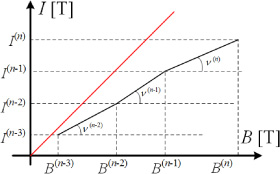
Reconstruction example of arbitrary segments of I-B dependence.
The magnetic circuit of the device is made from low remanence iron, with the B-H dependence presented in Fig. 8.
The columns have a 20 mm × 20 mm cross-sectional area and 100 mm height, with a yoke distance of 40 mm. The auxiliary air-gap was set at 1.5 mm. To take into account the technological air-gaps, four small paper sheets, of 0.1 mm thickness, were placed between the column and yoke joints. The two DC coils have N = 1620 turns.
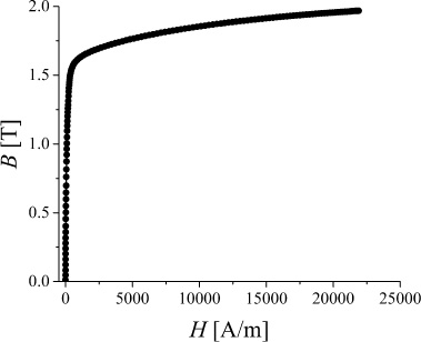
B-H relationship for the magnetic circuit material.
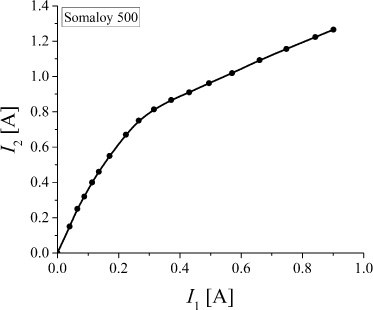
Variation of i 2 versus i 1 currents measured with the proposed device for Somaloy 500 cubic sample.
The material used for the validation of the experimental procedure and developed set-up is a commercial soft magnetic composite (Somaloy 500). Two samples were involved in the study. The B-H relationship of the first sample that was prepared as a cubic one with a 20-mm side, was determined, using the proposed experimental device. As a reference a toroidal sample of 50 mm mean diameter and with a cross-sectional area of 5 mm × 5 mm, was characterized, using a metrologically calibrated hysteresis graph-wattmeter with digital control of the magnetic flux density waveform.
The measurements were performed at 1 Hz, having a 200-winding field coil connected to a NF HSA4101 power amplifier, controlled by an Agilent 33210 A arbitrary function generator. The magnetic flux coil has 20 windings and the form factor of the secondary voltage was equal to 1.1102 ± 0.4% [5,20]. The measuring frequency of 1 Hz was considered low enough, because, in the case of this composite magnetic material, that has the magnetic permeability 𝜇 r = 500 and the electrical resistivity 𝜌 = 70 μΩm, the electromagnetic field skin depth is about 18 cm, value that is much higher than 5 mm [5,21].
In Fig. 9 are presented the (i 1, i 2) pair of currents, in the case of cubic sample, measured with the developed device. Using the magnetic circuit model and the numerical computation of the inverse problem, the B-H relationships, presented in Fig. 10, are obtained. Two 0.2 mm air-gaps were used to take into consideration in the numerical computation the technological air-gaps. Unlike the finite element method, the GFM permits a simple and easy consideration of these air-gaps, however small they may be.
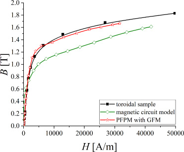
B-H relationship obtained for toroidal and cubic samples.
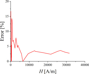
Error variation versus magnetic field strength between the B-H relationships of toroidal and cubic samples.
It can be observed from Fig. 10 and Fig. 11 that a low error computed according to Eq. (6):
The magnetic circuit model in comparison with the inverse magnetic field problem method has some important advantages: the analysed structure is 3D, reduced computation time, very good stability, because the (B, H) pairs are calculated independently without taking into account the previous values. The inverse magnetic field problem computation permits a field distribution as close to the real configuration. It can be applied to different sample shapes, although the computation time is relatively long (8 hours on a notebook with 2 GHz Intel processor), and it is not recommended to extend the procedure to 3D structures.
Footnotes
Acknowledgements
The work of V. Manescu (Paltanea), G. Paltanea and P.C. Andrei has been funded by U.P.B., through “Excellence Research Grants” Program, UPB-GEX 2017. Identifier: UPB-GEX2017, Ctr. No. 04/25.09.2017 (OPTIM-IE4), Ctr. No. 02/25.09.2017 (ANIZ-GO) and Ctr. No. 06/25.09.2017 (STATIC-BH). The measurement on the toroidal sample, was done at Istituto Nazionale di Ricerca Metrologica (INRIM), Turin, Italy. Dr. Fausto Fiorillo and Dr. Enzo Ferrara are acknowledged for providing the instrumental apparatus at INRIM and discussing experiments and results. The work of I. F. Hantila and C. Grumeza has been funded by a grant of CNCS/CCCDI – UEFISCDI, Project Number 10PTE/2016, within PNCDI III “Brushless servo-motors series utilizing soft magnetic composite materials”.