
Abstract
Permanent magnet machine adopting Halbach array has more sinusoidal air-gap flux density distribution and higher air-gap flux density magnitude. Compared with the equal segmented Halbach array, the fundamental magnitude of air gap flux density can be higher and distortion rate can be lower by reasonably designing each segment width in unequal segmented Halbach array. Thus, in this paper, the permanent magnet machine adopting unequal segmented Halbach array is researched. Firstly, an analytical model is established for PM machine adopting Halbach array to improve the calculation efficiency. This analytical model can be applied to the Halbach array having arbitrary pole pair number, arbitrary number of segments per pole, arbitrary segment width and arbitrary gap width between segments. Further, the calculation results for air gap flux density between analytical model and finite element method are compared to verify the analytical model. In addition, the method to determine each segment width in the unequal segmented Halbach array is proposed firstly in this paper. On this basis, effects of the gap width between segments and each segment width under one pole on air gap flux density are researched. The research conclusions will provide guidance for the design and fabrication of unequal segmented Halbach array.
Keywords
Introduction
The Halbach array is firstly proposed by Halbach in 1980s [1]. Compared with the permanent magnet (PM) machine adopting other magnetizing patterns, the PM machine adopting Halbach array has some advantages, such as better assembled magnetic effect, more sinusoidal air gap flux density distribution, and more sinusoidal back electro motive force (back EMF) etc. [2,3]. The Halbach array can be divided into two categories according to the manufacturing method, that is the ring Halbach array and the segmented Halbach array. Special magnetizing device is needed for manufacturing ring Halbach array, which makes the manufacture of ring Halbach array difficult. The segmented Halbach array can be achieved by assembling the magnetized blocks in a certain order. Compared with the ring Halbach array, the manufacture of segmented Halbach array is relatively easy, so it is commonly used in the engineering field.
Halbach array has been widely used in the machine field to achieve excellent electromagnetic performances. In recent years, many scholars have proposed many new geometries aiming at Halbach array in order to optimize the electromagnetic performances of machine further. Reference [4] proposes a kind of Halbach array whose segments under one pole have different heights. Effects of each segment height on air gap flux density, electromagnetic torque and torque ripple are researched in this reference. On this basis, reference [5] further researches effects of different combinations of height and material in segments under one pole on air gap flux density, electromagnetic torque and torque ripple. Reference [6] proposes a kind of new two-segmented Halbach array structure whose magnetizing directions are different from the common two-segmented Halbach array. Compared with the common two-segmented Halbach array, this new two-segmented Halbach array can effectively improve the fundamental magnitude of air gap flux density. Reference [7] proposes a new kind of two-layer Halbach array, which can effectively improve the air gap flux density and electromagnetic performances. On the basis of reference [7], a kind of trapezoidal Halbach array is proposed in reference [8]. Reference [9] proposes a kind of segmented eccentric Halbach array. Compared with the common three-segmented Halbach array, when the PM machine adopts this new Halbach array, the average electromagnetic torque is larger, the torque ripple is lower and the usage of PM is decreased. Aiming at the multi-phase PM machine, a new kind of Halbach array geometry which can add the third harmonic content of air gap flux density is proposed in reference [10]. Compared with the common Halbach array, the torque density of machine is significantly improved after adopting the new Halbach array. In the above different kinds of Halbach arrays, each segment width per pole is almost the same. There are few researches aiming at the unequal segmented Halbach array. Reference [11] establishes the analytical model for permanent magnet machine adopting unequal segmented Halbach array. However, the relationships among each segment width are not derived, and effects of each segment width on air gap flux density are not analyzed. Hence, in this paper, the magnetic field in machine adopting unequal segmented Halbach array will be researched in detail, which will provide guidance for the design and fabrication of unequal segmented Halbach array.
It is necessary to establish the analytical model for PM machine adopting unequal segmented Halbach array to research effects of related parameters in unequal segmented Halbach array on air gap flux density efficiently and conveniently. Among many analytical methods, sub-domain model method is a fast and accurate analytical modeling method, which is widely used in the surface mounted PM machine. Based on the sub-domain model method, reference [12] establishes analytical model for permanent magnet machine with nonuniform slots, and researches effect of nonuniform slot on cogging torque. Reference [13] establishes analytical model for PM machine adopting two-segmented Halbach array whose magnetizing directions are radial and tangential respectively under one pole. Meanwhile, effects of width ratio between two segments on torque ripple and maximum torque are analyzed by using the established analytical model. Reference [14] establishes analytical model for PM machine adopting segmented Halbach array. It is worth mentioning that the established analytical model can be used for both external rotor PM machine and internal rotor PM machine topologies. Further, optimal design for PM machine is conducted by using the analytical model in reference [14]. References [15,16] establish analytical models for PM machines adopting some kinds of typical Halbach array. References [17,18] establish analytical models for PM machines adopting modular Halbach array considering the gap between poles. Reference [19] establishes analytical model for permanent magnetic bearing adopting Halbach array with arbitrary segmented magnetized angle. However, above references do not consider the effect of gap between segments under one pole. Aiming at this question, reference [20] establishes analytical model for PM machine adopting segmented Halbach array considering the gap between segments under one pole.
In this paper, unequal segmented Halbach array is proposed to apply to surface mounted PM machine. Firstly, analytical model for PM machine adopting unequal segmented Halbach array is established to improve the calculation efficiency. The established analytical model can be applied to the Halbach array that has arbitrary pole pair number, arbitrary number of segments per pole, arbitrary segment width, and arbitrary gap width between segments. Meanwhile, air gap flux density is calculated by analytical method and FEM respectively to verify the established analytical model. Simultaneously, the method to determine each segment width in unequal segmented Halbach array is firstly proposed in this paper. On this basis, effects of the gap width between segments and segment widths under one pole on air gap flux density are researched, which will provide guidance for the design of unequal segmented Halbach array.
Unequal segmented Halbach array and analytical modeling
Unequal segmented Halbach array
In the segmented Halbach array, the Halbach array will present three types when each segment width under one pole takes different values, as shown in Fig. 1. Among them, Type1 represents a kind of Halbach array that the middle segment width under one pole is the maximum, and the widths of other segments decrease gradually from the middle to two sides. Type2 represents a kind of Halbach array that each segment width under one pole is equal, that is, it is the equal segmented Halbach array. Type3 represents a kind of Halbach array that the middle segment width under one pole is the minimum, and the widths of other segments increase gradually from the middle to two sides.
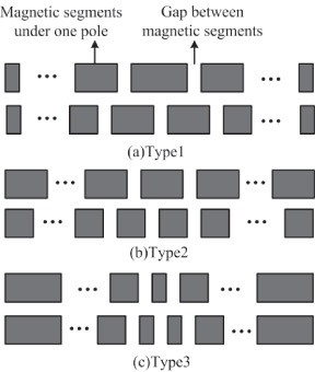
Different types of segmented Halbach arrays.
In the PM machine adopting unequal segmented Halbach array, p represents the pole pair number, and l represents the number of segments per pole. 𝛼pa represents the ratio between the gap width between segments and pole pitch. The ratio between each segment width and pole pitch is represented by 𝛼pc(1), 𝛼pc(2), …, 𝛼pc(l) respectively under one pole. The relationships among 𝛼pc(1), 𝛼pc(2), …, 𝛼pc(l) and 𝛼pa satisfy the formula (1).
When the number of segments per pole l is odd number, the position of θ = 0 corresponds to the middle of the (l +1)∕2-th segment under one pole, that is the middle of one pole, as shown in Fig. 2(a). Further, 𝛼p(1), 𝛼p(2), …, 𝛼p(l) are introduced to make the Fourier decomposition easy, and they are corresponding to 𝛼pc(1), 𝛼pc(2), …, 𝛼pc(l) one by one, as shown in formula (2).
Correspondingly, when the number of segments per pole l is even number, the position of θ = 0 corresponds to the middle of gap between the l∕2-th segment and the (l +2)∕2-th segment, which is also the middle of one pole, as shown in Fig. 2(b). Similarly, 𝛼p(1), 𝛼p(2), …, 𝛼p(l) are introduced to make the Fourier decomposition easy, and they are corresponding to 𝛼pc(1), 𝛼pc(2), …, 𝛼pc(l) one by one, as shown in formula (3).

Variables diagram in unequal segmented Halbach array.
It is necessary to establish the analytical model for PM machine adopting unequal segmented Halbach array in order to research magnetic field fast and accurately. In the modeling process, the PM machine adopting unequal segmented Halbach array is divided into three regions to establish the analytical model, as shown in Fig. 3. In Fig. 3, region I and region III are the air gap regions, and region II is the unequal segmented Halbach array region. When the PM machine is the internal rotor topology, region I is the effective air-gap region, and region III is iron-cored rotor when R mi = R i or air-cored rotor when R i → 0. Similarly, when the machine is the external rotor topology, region III is the effective air-gap region, and region I is iron-cored rotor when R mo = R o or air-cored rotor when R o →∞.

Sub-domain model diagram of PM machine.
To simplify the analysis process of magnetic field, some assumptions are made as follows: The demagnetization curve of permanent magnet is linear; The gap widths between segments under one pole are the same; The permeability of ferromagnetic material is infinite; End effect is ignored, that is, the machine is infinitely long; The effects of stator slots are ignored.
The analytical model is established for PM machine adopting unequal segmented Halbach array under no-load condition. The current density is zero in the whole solution domain, so the magnetic field is an irrotational field, and the scalar potential φ is introduced to solve no-load magnetic field.
In region I and region III, the scalar potential satisfies the following equations as shown in formula (4) and formula (5) respectively:
In region II, the scalar potential satisfies the following equation as shown in formula (6):
The expression of the scalar potential in each region can be achieved by solving formula (4)–(6) combining with the boundary conditions between every two subdomains. Further, the flux density expression in each region can be obtained according to the relationship between the scalar potential and flux density [14,20]. In the solving process for flux density distribution in each region, the key is to solve the expressions of the nth radial and tangential harmonic components M rn and M θn of the residual magnetization vector.
Each segment in the Halbach array has its specific magnetizing direction, as shown in Fig. 3. θm, i
represents the angle between θ = 0 and the magnetizing direction of the ith (i = 1, 2, …, 2pl) segment under one pole, and the corresponding calculation formula is shown in formula (7).
Period of the radial component M
r and the tangential component M
θ of the residual magnetization vector is 2π∕p. When the number of segments per pole is odd number, the expressions of M
r and M
θ are shown as formula ((10)) and formula ((11)) in the range of [0, π∕p], and the expressions of M
r and M
θ are shown as formula ((12)) and formula ((13)) in the range of [π∕p, 2π∕p]. Further, the expressions of M
rn
and M
θn
are shown as formula ((14))–((15)).
When the number of segments per pole is even number, the expressions of M
r and M
θ are shown as formula (16) and formula (17) in the range of [0, 2π∕p]. Further, the expressions of M
rn and M
θn are shown as formula (18)–(19).
In this section, a 4-pole internal rotor PM machine adopting unequal segmented Halbach array is set as an example to verify the established analytical model. The related parameters of the machine are shown in Table 1 in detail.
Parameters of machine
Parameters of machine
Firstly, the number of segments per pole is set to 4, and the arc angles corresponding to each segment width under one pole are set to 14.49°, 26.91°, 26.91°, and 14.49° respectively. The arc angle corresponding to the gap width between segments is set to 1.8°. The air gap flux density waveforms calculated by the finite element method (FEM) and the established analytical model are shown in Fig. 4.
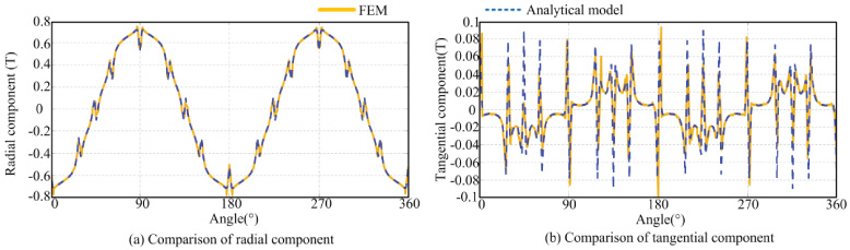
Comparison of air gap flux density between two methods when l is 4.
Similarly, the number of segments per pole is set to 5, and the arc angles corresponding to each segment width under one pole are set to 11.34°, 16.2°, 25.92°, 16.2°, and 11.34° respectively. The arc angle corresponding to the gap width between segments is set to 1.8°. The air gap flux density waveforms calculated by the finite element method (FEM) and the established analytical model are shown in Fig. 5.
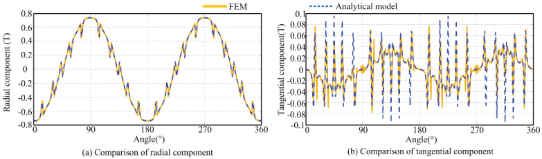
Comparison of air gap flux density between two methods when l is 5.
Meanwhile, the fundamental magnitudes and distortion rates of air gap flux density waveforms achieved by FEM and established analytical model are listed in Table 2.
Fundamental magnitudes and distortion rates of air gap flux density waveforms by two methods
It can be seen from Fig. 4, Fig. 5 and Table 2 that when the number of segments per pole takes odd number and even number respectively, the calculated results of air gap flux density by the established analytical model are well consistent with the results by FEM. Therefore, the established analytical model for PM machine adopting unequal segmented Halbach array is verified.
In this section, effects of related parameters in unequal segmented Halbach array on fundamental magnitudes and distortion rates of air gap flux density are researched based on the established analytical model. The related parameters of machine used in this section are listed in Table 1.
The calculation formula for distortion rate THD of air gap flux density is shown as formula (20)
In this section, when the number of segments per pole takes different values, effects of the gap width between segments on air gap flux density are researched in three types of Halbach arrays shown in Fig. 1.
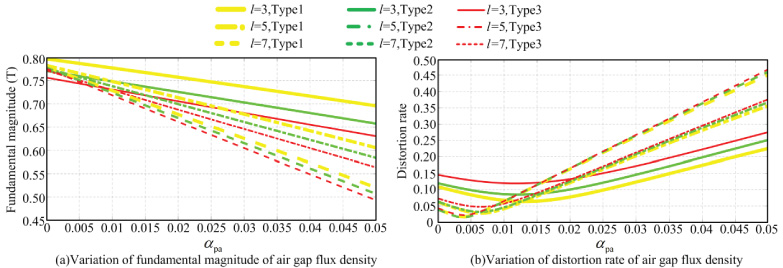
Figure 6 and Fig. 7 show the effects of the gap width between segments on fundamental magnitude and distortion rate of air gap flux density in three types of Halbach arrays. It can be seen from Fig. 6 and Fig. 7 that under different numbers of segments per pole and different Halbach array types, the fundamental magnitudes of air gap flux density all show a decreasing trend with the increase of the gap width between segments. This is because the total width of permanent magnet per pole decreases with the increase of the gap width between segments, which results in the decrease of flux area provided by permanent magnet. In addition, distortion rates decrease first and then increase with the increase of the gap width between segments. When the numbers of segments per pole take the same values and the Halbach arrays take different types, the gap widths between segments to make distortion rate of air gap flux density minimum are the same. In addition, the gap width between segments to make distortion rate of air gap flux density minimum decreases with the increase of the number of segments per pole, and the specific values are shown in Table 3. The reason may be that the total gap widths under one pole to make distortion rate minimum should remain unchanged or show a decreasing trend. Hence, with the increase of number of segments per pole, the gap width between segments to make distortion rate of air gap flux density minimum decreases.
Variation of air gap flux density with variation of the gap width between segments when l is odd number.
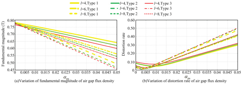
Variation of air gap flux density with variation of the gap width between segments when l is even number.
The gap width between segments 𝛼 pa to make distortion rate of air gap flux density minimum under different numbers of segments under one pole
In addition, it can be seen from Fig. 6 and Fig. 7 that under certain number of segments per pole and certain gap width between segments, the air gap flux density waveform under the Type1 unequal segmented Halbach array is better (larger fundamental magnitude and lower distortion rate) than that under the Type2 equal segmented Halbach array. Because the middle segment in one pole is corresponding to the amplitude position of air gap flux density under one pole, larger middle segment width can make fundamental magnitude of air gap flux density larger. Therefore, when the number of segments per pole takes different values, the air gap flux density waveform under unequal segmented Halbach array can be better than that under equal segmented Halbach array by reasonably designing each segment width per pole.
Each segment width per pole needs to be firstly determined in order to research their effect on air gap flux density. In this section, a method to determine each segment width per pole is proposed firstly.
When the number of segments per pole is odd number, the middle segment width 𝛼pc((l + 1)∕2) needs to be given firstly, and then the widths of other segments satisfy the formula (21).
In the research process, an assumption is made that the values from 𝛼pc(1) to 𝛼pc((l − 1)∕2) are a series of equal difference numbers, and the variance is represented by d. Hence, 𝛼pc(1), …, 𝛼pc((l − 5)∕2), 𝛼pc((l − 3)∕2) can be expressed as formula (22).
Substituting formula (22) into formula (21), formula (23) can be achieved.
When the middle segment width 𝛼pc((l + 1)∕2) takes different values, the values of K and k 1 change correspondingly. When the value of 𝛼pc((l + 1)∕2) is less than k 1, which illustrates that the middle segment width is smaller, the widths of other segments increase gradually from middle to two sides. That is, d is positive value. At this time, the value of 𝛼pc((l − 1)∕2) needs to satisfy the relationship: 𝛼pc((l + 1)∕2) < 𝛼 pc((l − 1)∕2) ≤ k 1.
Correspondingly, when the value of 𝛼pc((l + 1)∕2) is greater than or equal to k
1, which illustrates that the middle segment width is larger, the widths of other segments decrease gradually from middle to two sides. That is, the value of d is negative. At this time, the value of 𝛼pc((l − 1)∕2) needs to satisfy the relationship: k
1 ≤ 𝛼pc((l − 1)∕2) < min(𝛼pc((l + 1)∕2), y
max), and the value of y
max needs to satisfy the following expression
After giving the values of 𝛼pc((l + 1)∕2) and 𝛼pc((l − 1)∕2), the variance d can be obtained by formula (23). Then, the widths of other segments can be achieved.
Similarly, when the number of segments per pole is even number, the middle segment width 𝛼pc(l∕2) needs to be given firstly to achieve each segment width under one pole, and then the widths of other segments satisfy the formula (24).
Similarly, the values from 𝛼pc(1) to 𝛼pc((l − 2)∕2) are a series of equal difference numbers, and the variance is represented by d. Hence, 𝛼pc(1), …, 𝛼pc((l − 6)∕2), 𝛼pc((l − 4)∕2) can be expressed as formula (25).
Substituting formula (25) into formula (24), formula (26) can be achieved.
When the middle segment width 𝛼pc(l∕2) takes different values, the values of K and k 1 change correspondingly. When the value of 𝛼pc(l∕2) is less than k 1, which illustrates that the middle segment width is smaller, the widths of other segments increase gradually from middle to two sides. That is, the value of d is positive. At this time, the value of 𝛼pc((l − 2)∕2) needs to satisfy the relationship: 𝛼pc(l∕2) < 𝛼pc((l − 2)∕2) ≤ k 1.
When the value of 𝛼pc(l∕2) is greater than or equal to k
1, which illustrates that the middle segment width is larger, the widths of other segments decrease gradually from middle to two sides. That is, the value of d is negative. At this time, the value of 𝛼pc((l − 2)∕2) needs to satisfy the relationship: k
1 ≤ 𝛼pc((l − 2)∕2) < min(𝛼pc(l∕2), y
max), and the value of y
max needs to satisfy the following expression
After giving the values of 𝛼pc(l∕2) and 𝛼pc((l − 2)∕2), the variance d can be obtained by formula (26). Then, the widths of other segments can be achieved.
When the number of segments per pole is 3, the value of 𝛼pc(1) can be achieved according to the corresponding value of K after giving the value of 𝛼pc(2). Meanwhile, the value of 𝛼pc(3) is equal to 𝛼pc(1) according to formula (1). Similarly, when the number of segments per pole is 4, the value of 𝛼pc(1) can be achieved according to the corresponding value of K after giving the value of 𝛼pc(2). Meanwhile, the value of 𝛼pc(3) is equal to 𝛼pc(2) and the value of 𝛼pc(4) is equal to 𝛼pc(1) according to formula (1).
Based on above derived expressions, effects of the middle segment width on air gap flux density is firstly researched when the number of segments per pole takes 3 and 4 respectively, as shown in Fig. 8. Another point to make is that in the research process, the values of 𝛼pa are selected to the values making distortion rate of air gap flux density minimum under different numbers of segments per pole, that is, the values listed in Table 3.
It can be seen from Fig. 8(a) that when the number of segments per pole is 3, the fundamental magnitude of air gap flux density increases gradually, and the distortion rate decreases first and then increases with the increase of the middle segment width. The reason may be that the wider the middle segment width is, the wider the width corresponding to the amplitude position of air gap flux density will be. Hence, wider middle segment width may make fundamental magnitude of air gap flux density larger and distortion rate lower. However, when the middle segment width is too large, the air gap flux density waveform will be close to trapezoidal wave, which may make the distortion rate of air gap flux density higher. Similarly, when the number of segments per pole is 4, it can be seen from Fig. 8(b) that with the increase of middle segment width, the fundamental magnitude of air gap flux density increases first and then decreases, and the distortion rate decreases first and then increases.
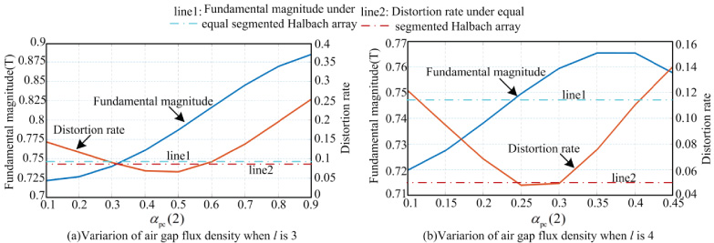
Variation of air gap flux density with the variation of the middle segment width when l is 3 and 4.
When the number of segments per pole is odd number and larger than 3 or the number of segments per pole is even number and larger than 4, each segment width under one pole is determined according to formula (21)–formula (26).
When the number of segments per pole l takes 5 and 7, effects of segment widths on air gap flux density are researched respectively, as shown in Fig. 9 and Fig. 10.
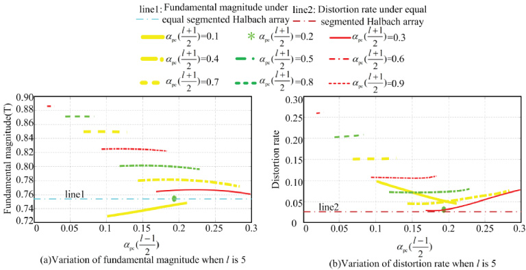
Variation of air gap flux density with the variation of the segment width when l is 5.

Variation of air gap flux density with the variation of the segment width when l is 7.
It can be seen from Fig. 9 and Fig. 10 that with the increase of the middle segment width 𝛼pc((l + 1)∕2), the fundamental magnitude of air gap flux density increases gradually, and the distortion rate decreases first and then increases. The variation trend is in accordance with that when l is 3. When the value of 𝛼pc((l + 1)∕2) is 0.1, 𝛼pc((l + 1)∕2) is less than the corresponding k 1, and the variance d is greater than 0, that is, the type of Halbach array is corresponding to Type3 in Fig. 1. At this time, with the increase of the 𝛼pc((l − 1)∕2), the fundamental magnitude of air gap flux density increases gradually, and the distortion rate decreases gradually. When the value of 𝛼pc((l + 1)∕2) takes value from 0.2 to 0.9, 𝛼pc((l + 1)∕2) is larger than the corresponding k 1, and the variance d is less than 0, that is, the type of Halbach array is corresponding to Type1 in Fig. 1. At this time, with the increase of 𝛼pc((l − 1)∕2), the fundamental magnitude of air gap flux density increases first and then decreases, and the distortion rate decreases first and then increases.
Correspondingly, when the number of segments per pole l takes 6 and 8, effects of segment widths on air gap flux density are researched respectively, as shown in Fig. 11–Fig. 12.
It can be seen from Fig. 11 and Fig. 12 that with the increase of middle segment width 𝛼pc(l∕2), the fundamental magnitude of air gap flux density increases first and then decreases, and the distortion rate decreases first and then increases. The variation trend is in accordance with that when l is 4. When the value of 𝛼pc(l∕2) is 0.1 or 0.15 when l is 6 and is 0.1 when l is 8, 𝛼pc(l∕2) is less than the corresponding k 1, and the variance d is greater than 0, that is, the type of Halbach array is corresponding to Type3 in Fig. 1. At this time, with the increase of 𝛼pc((l − 2)∕2), the fundamental magnitude of air gap flux density increases gradually, and the distortion rate decreases gradually. When the value of 𝛼pc(l∕2) takes value from 0.2 to 0.45 when l is 6 and takes value from 0.15 to 0.45 when l is 8, 𝛼pc(l∕2) is larger than the corresponding k 1, and the variance d is less than 0, that is, the type of Halbach array is corresponding to Type1 in Fig. 1. At this time, with the increase of 𝛼pc((l − 2)∕2), the fundamental magnitude of air gap flux density increases first and then decreases, and the distortion rate decreases first and then increases.

Variation of air gap flux density with the variation of the segment width when l is 6.

Variation of air gap flux density with the variation of the segment width when l is 8.
On the whole, whether the number of segments per pole l is odd number or even number, the variation laws of fundamental magnitudes and distortion rates of air gap flux density with the segment widths are almost the same. Meanwhile, the fundamental magnitudes and distortion rates of air gap flux density have a greater change with the variation of the middle segment width compared with the widths of other segments under one pole. Therefore, the middle segment width has a greater effect on the air gap flux density compared with the widths of other segments. The main reason may be that the middle segment in one pole is corresponding to the amplitude position of air gap flux density under one pole.
In addition, it can be seen from Fig. 8–Fig. 12 that when the number of segments per pole takes different values, there are unequal segmented Halbach arrays to make both the fundamental magnitude and distortion rate of air gap flux density better than that adopting the equal segmented Halbach array. Meanwhile, it is found by analysis that the unequal segmented Halbach arrays to make air gap flux density waveform better are all the Type1 unequal segmented Halbach array. This is because the larger middle segment width may make air gap flux density waveform better according to above analysis, and the middle segment width is larger in Type1 Halbach array. Thus, under arbitrary number of segments per pole, the unequal segmented Halbach array to make air gap flux density waveform better can always be achieved by reasonably selecting each segment width under one pole.
In this paper, the unequal segmented Halbach array is applied to the PM machine. Analytical model for PM machine adopting unequal segmented Halbach array is established, and its validation is verified by FEM. In addition, the established analytical model can be applied to the Halbach array that has arbitrary pole pair number, arbitrary number of segments per pole, arbitrary segment width, and arbitrary gap width between segments. Simultaneously, the method to determine each segment width in unequal segmented Halbach array is proposed firstly. Based on this, effects of the gap width between segments and segment widths under one pole on the fundamental magnitude and distortion rate of air gap flux density are researched. Some conclusions are drawn as follows: With the increase of the gap width between segments, the fundamental magnitude of air gap flux density decreases gradually, and the distortion rate decreases first and then increases; Under the same number of segments per pole, the gap widths between segments to make distortion rate of air gap flux density minimum are the same under different types of Halbach arrays; With the increase of the number of segments per pole, the gap width between segments to make distortion rate of air gap flux density minimum decreases gradually; Compared with widths of other segments, the middle segment width has a greater effect on air gap flux density waveform; Under different numbers of segments per pole, with the increase of middle segment width, fundamental magnitudes of air gap flux density show an increasing trend, and the distortion rates decrease first and then increase. Under arbitrary number of segments per pole, the unequal segmented Halbach array to make air gap flux density waveform better is always the Type1 unequal segmented Halbach array.
Footnotes
Acknowledgements
This work was supported in part by the project supported by Major Program of National Natural Science Foundation of China under grant 51991384, in part by the project supported by Tianjin Natural Science Foundation under Grant 19JCYBJC21800, and in part by the Tianjin College Innovation Team Training program of China under grant TD13-5039.