



Abstract
This work presents the development of an optimal segmented-rotor switched reluctance machine (SSRM) for the application as belt-driven starter/generators in hybrid electric vehicles. Different from conventional switched reluctance machines, the stator of the SSRM consists of two types of poles, i.e., exciting and auxiliary poles, and the rotor consists of a series of discrete segments. The initial design of this new SSRM is obtained based on the specifications of the belt-driven starter/generators. To improve the steady-state and dynamic performances in the practical operation, six important parameters, including two coefficients of stator and rotor poles, the stator inner diameter, radial height of rotor segment, and the turn-on and turn-off angles are optimized to maximize the output torque and minimize the core loss. Then, the overall performances before and after optimization are compared. It is found that the obtained optimal SSRM exhibits better flux linkage and inductance characteristics, and higher torque and output power within the whole speed range. Moreover, for the generator performance, the SSRM after optimization exhibits higher power and efficiency under the same speed. Finally, to validate the analysis method, a prototype is built and its steady-state and dynamic performances are verified by the experimental results.
Keywords
Introduction
The technological transition from conventional vehicles to battery electric vehicles has triggered an extensive research activity in the field of hybrid electric vehicles (HEVs) [1–6]. The belt-driven starter/generator (BSG), as a cost-effective solution, has been widely employed in HEVs to improve the performance of the system and reduce the fuel consumption [7–10]. The idle start-stop function of the BSG can significantly benefit the HEVs in the areas with heavy traffic like urban streets. The engine operation is ceased to eliminate fuel consumption and emissions when the vehicle stops temporarily. Then the engine restarts automatically by the BSG machine [11,12].
Electrical machine is the heart of the BSG system, which is functioned as motor and generator. Induction machines (IMs) and permanent magnet (PM) machines are popular alternatives to the BSGs. However, the conventional IMs suffer from low power factor and high operation temperature [13–18]. For PM motors, the high material cost of PMs and demagnetization under high temperature limit their promotion [19–23].
On the other hand, switched reluctance machines (SRMs) have some advantages for application in BSG, such as simple and robust structure, independent control of each winding, low cost, and high starting torque [24–26]. However, conventional SRMs have some inherit drawbacks, such as high torque ripple and insufficient torque [27–30]. During the last decades, some researches have been presented to solve these problems. In [31], different combinations of the stator-rotor poles of SRMs were investigated to produce higher torque and lower torque ripple. Segmented-rotor SRMs were firstly proposed in [32], and it is found that this type of motor can produce over 40% more torque than the conventional SRM with the same dimensions. Furthermore, in [33], a novel SSRM was proposed and the stator poles were classified into exciting and auxiliary poles to increase the electrical utilization and torque density. In [34], a novel segmented type SRM with a 2-steps slide or skew rotor was proposed to reduce the torque ripple, but the average torque is reduced as well. Moreover, segmented-stator SRMs were also investigated for the application in industry. A novel high-torque stator-segmented SRM using distinct concepts was designed in [35], and it is proved that the proposed SRM exhibits higher torque density than the conventional SRM. In [36], an E-core 6/10 SRM has been modified to an improved 9/12 two-phase E-core SRM to further improve the average torque. The results show that the torque of the modified SRM can be improved by about 35% under the same dimensions. In [37], a novel axial field SRM with single tooth stator and segmental rotor was developed to increase the output torque and the operation efficiency. Besides, the iron loss and the weight of the rotor have been reduced. In [38], an axial flux segmented rotor SRM was designed to reduce torque ripple without any axial forces exerted on the stator. These works mainly focus on the development of new motor structures rather than parameter optimization.
In [39], an optimization method was presented to acquire the best structural parameters to maximize the torque per unit loss based on the static finite-element analysis (FEA). However, this optimization approach does not take into account the estimation of the dynamic performance, making the assessment of torque per unit loss and efficiency difficult to be achieved. In [40], the optimization of the conventional SRMs has been investigated to improve the machine performance. Optimization parameters include the ratio of the tooth width to the pitch, the ratio of the rotor diameter to the stator outer core diameter, and the core width. However, the torque performances of these SRMs are limited by the differential of dL∕dθ (the difference of inductance between the aligned and unaligned positions to the half cycle angle).
To solve these problems, a new SSRM was proposed in our previous work [41]. Different from those conventional SRMs, the stator of the SSRM consists of two types of poles, i.e., exciting and auxiliary poles. The width of the exciting pole is twice as large as that of the auxiliary pole. In addition, the rotor consists of a series of discrete segments. Based on FEA, it is found that this motor has lower mutual inductance and better fault-tolerance ability compared with conventional SRMs [42,43]. However, the preliminary simulation analysis only focused on concept design and fundamental characteristics. In this paper, the overall performances of the machine are investigated in terms of the design specifications and optimization. Furthermore, the simulation results are verified by the experimental results.
To achieve these goals, this work aims to present the comprehensive design and optimization of this new SSRM to improve its steady-state and dynamic performances for BSG application in HEVs. The optimization concerns include the maximization of torque, dL∕dθ, and the minimization of the core loss as well as the assessment of the dynamic performance. The remainder of this work is organized as follows. Section 2 presents the design analysis, steady-state and dynamic performances of an initial design of the SSRM. Section 3 investigates the optimization method and results for the SSRM. Section 4 presents the comparison of the detailed steady-state and dynamic performances for the initial and optimized motors. The prototype, test results and discussions are presented in Section 5, followed by the conclusions.
Initial design
Initial specification
Figure 1 shows the structure of the BSG system. As shown, the BSG machine is connected to the engine by the belt in the front of the engine to replace the original generator. Thus, the BSG machine integrates the starter and generator.
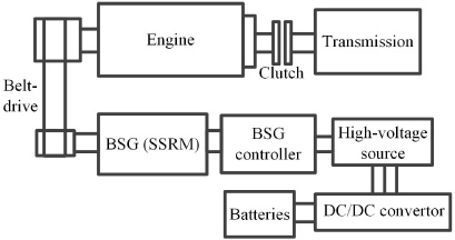
Structure of the BSG system.
Table 1 lists the specifications of the BSG machine. The rated torque T can be calculated by
Specifications of the BSG machine
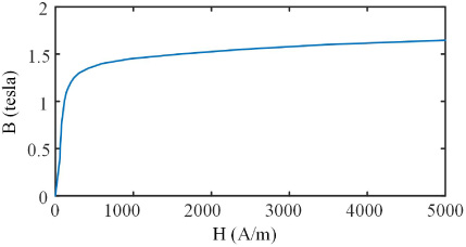
The BH curve of the material DW310.
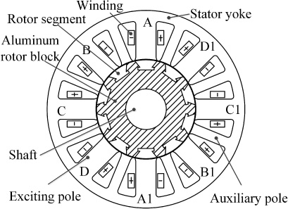
A cross-sectional view of the SSRM1.
Parameters of the Initial SSRM (SSRM1)
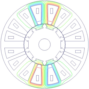
Flux distribution at aligned position.
The topology and operation principle of the BSG machine can be seen in [41]. The initial design can be determined based on the specifications listed in Table 1 and the limited space according to experience. The initial machine topology is shown in Fig. 3. The stator has two types of poles: exciting poles and auxiliary poles. The exciting poles are wound by windings, while the auxiliary poles are only functioned as flux return paths without any windings. The rotor contains ten discrete segmented rotors, and each component is embedded in the nonmagnetic isolator. The 2D simulation model is established in Ansoft/Maxwell, The control method is angle position control (APC) and the voltage is set as 60 V. Then, mesh generation, boundary conditions and analysis setup are determined.
Table 2 lists the main parameters of the initial design SSRM (SSRM1). The flux distribution at aligned position is shown in Fig. 4. At the aligned position, the magnetic flux flows down from the exciting stator pole, through the segmented-rotor and returns via the adjacent auxiliary poles.
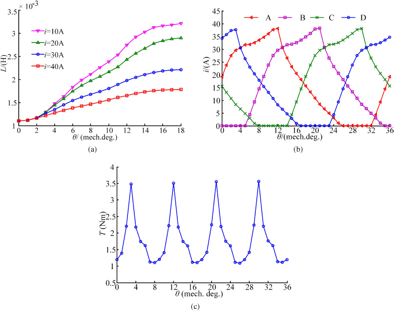
Steady-state and dynamic performances of the SSRM1: (a) Inductance characteristics, (b) current waveform, and (c) output torque waveform.
Figure 5(a) shows the phase inductance characteristics of the SSRM. As shown, the ratio of the maximum inductance to the minimum inductance is small, which results in insufficient output torque. The performance of SSRM1 is analyzed by coupled simulation of FEA and asymmetric half-bridge power circuit. The excitation windings are alternately distributed with N and S, and the phase windings are in parallel. The turn-on angle θon is −4° and the turn-off angle θoff is 12°, referred to the unaligned position (0°). Figures 5(b) and (c) show the four-phase current and synthetic torque of the SSRM1 at the rated speed, respectively. As shown, the average torque of the initial machine (SSRM1) is 1.82 Nm, lower than the specification (2.865 Nm). Therefore, this initial design should be improved through an optimization process.
Optimization
Figure 6 shows the flowchart of the proposed optimization process. It can be divided into the following five steps.
Step 1: Build the optimization models both in motor and control levels for the SSRM applied in BSG system.
Step 2: Carry out the sensitivity analysis for all the parameter in the drive system, including the motor and control parameters.
Step 3: Select the optimization parameters according to the results of sensitivity analysis.
Step 4: Optimize the motor parameters in sequence.
Step 5: Optimize the control parameters in sequence.

Optimization flowchart.
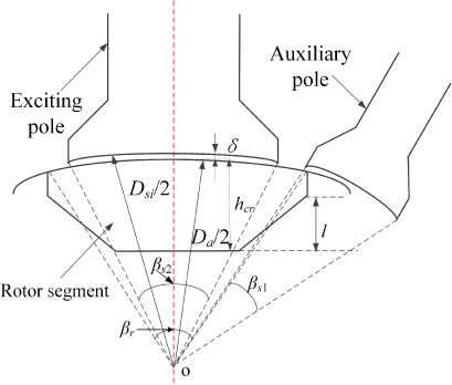
Model for illustration of the main optimization factors.
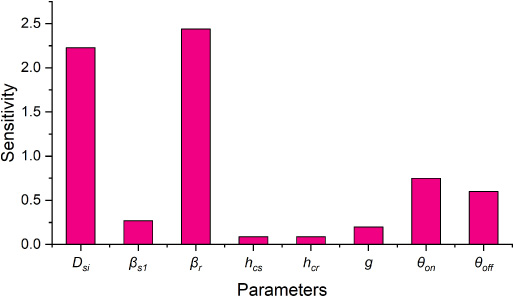
Sensitivity results of torque.
For the optimization of this SSRM, all the motor parameters including the exciting stator pole and rotor pole angles, 𝛽 s2 (𝛽 s2 = 2𝛽 s1, 𝛽 s1 is the auxiliary stator pole angle) and 𝛽 r , the inner diameter of the stator D si , the radial height of the rotor segment h cr , and air gap g, will be investigated in this work, as shown in Fig. 7. In addition, the control parameters turn-on angle θon and turn-off angle θoff are included in this optimization method.
To divide all the design parameters into the proposed subspaces, the local sensitivity analysis [44,45], which can reflect the influence/sensitivity of each parameter on the performances, are performed. Mathematically, the sensitivity of the ith parameter x
i
at the point
The whole sensitivity analysis is based on the FEA, and there is no accurate analytical expression of the objective function. Thus, in this case, a differential form is taken to calculate S
i
.
It should be noted that the sensitivities of different parameters calculated by (3) have different units. Thus, a normalization step considering absolute value is carried out as follows.
Figure 8 shows the local sensitivity analysis results of all the eight parameters. According to the results, D si , 𝛽 s1, 𝛽 r , θon and θoff are selected as the optimized parameters.
As the arcs of stator and rotor are related to the numbers of poles, two coefficients (𝛼
s2 and 𝛼
r
) are defined, which are the exciting stator pole arc coefficient and rotor pole arc coefficient, respectively, and they are given by
Based on linear assumption, the output torque of the SSRM can be expressed as
Therefore, the torque T is proportional to ΔL. The ratio of L
max and L
min is an important index to describe the performance of the SSRM, and it is defined as K in this work.
Therefore, six parameters, 𝛼 s2, 𝛼 r , D si , h cr , θon and θoff, will be investigated in the optimization to improve the motor performances.
For the optimization of motor parameters, the value of K is selected as the optimization objective. Since it is based on the static performance, the computational cost is smaller compared with the dynamic simulations. Besides, the static simulation does not require the extermal circuit, which reduce the complexity of process. The optimizaiton model can be defined as
For the optimization of control parameters, since it is based on the dynamic performance, the optimization model can be defined as
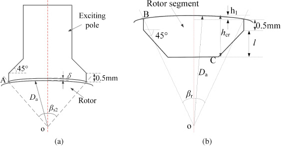
Parametric models: (a) Exciting pole, and (b) Rotor segment.
Figure 9 illustrates a parametric model of an exciting tooth and a rotor segment to show more details for the structural design parameters 𝛽
s2, 𝛽
r
, and h
cr
. Based on this figure, the coordinates of a point (A) at the pole shoe of the stator exciting tooth are
Similarly, the coordinates of a point (B) at the pole tip of the rotor are
Then a 2D FEA model can be developed based on (9) and (10).
Responses of K in terms of 𝛼 s2 and 𝛼 r .
Responses of K versus different inner diameters of the stator.
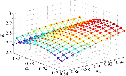
Figure 10 shows the responses of K (ratio of the maximum to the minimum inductance) in terms of different values for parameters 𝛼 s2 and 𝛼 r . As shown, for a given 𝛼 s2, the value of K increases first with the increase of 𝛼 r and then decreases with further increase of 𝛼 r . It can be seen that the difference between the two adjacent values in the ordinate of Fig. 10 is very small. That means even there is a little jump where when 𝛼 r is larger than 0.82, the error between the adjacent values is subtle. The main reason of this jump can be explained by the nonlinear characteristic of the SRM, especially for the calculation of inductance since the motor exists the saturated phenomena. It would reach the maximum when 𝛼 r is equal to 0.74. When the rotor pole coefficient is 0.74, the value of K increases with the enlargement of 𝛼 s2 (up to 0.95). Thus, the maximal K can be obtained when 𝛼 s2 is 0.95 and 𝛼 r is 0.74.
The parametric modeling method in Ansys Maxwell 2D is used to establish the parametric model of the inner diameter of the stator. When optimizing the stator inner diameter, the other stator variables remain static. As 𝛼
s2 = 0.95 and 𝛼
r
= 0.74 are fixed, then the coordinates of point A at the pole shoe of stator’s exciting tooth shown in Fig. 9 can be given as
Similarly, the coordinates of point B at the pole tip of the rotor segment can be written as
The other points can be expressed and adjusted appropriately in accordance with this point. Then, the parametric model of the inner diameter of the stator is established.
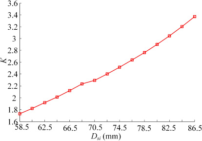
To meet the design specifications, the range of the inner diameter of the stator is 58.5 mm ∼ 86.5 mm. Figure 11 shows the responses of K versus the stator’s inner diameter D si . As shown, a linear relationship can be observed. The bigger the D si is, the higher the K can be obtained. However, considering the space of stator slots where the windings are embedded, the inner diameter of the stator is selected as 82.5 mm. Therefore, the optimal D si is selected as 82.5 mm, and then the corresponding K is 3.05.
Due to the large change of the stator slot, the length of the stator winding changes accordingly and the number of winding turns needs to be adjusted.
The optimized groove area (S
w
) can be given as
The stator groove depth d
s
can be expressed as
Therefore, the value of S
w
is 99 mm2, and the slot factor (k
s
) preset value is 0.53, and the relationship between k
s
and number of winding turns (N) can be given as
In order to meet the requirement of the slot factor, N is set to 24, and the number of parallel strands (N st ) is taken as 9.
The cross sectional area of the bare conductor of the winding (S
a
) can be calculated by
The one-phase windings of the studied SSRM are connected in parallel, and the total length of the windings (l
total) on each stator tooth can be given as
Therefore, the resistance of branch winding (R
A1) can be expressed as
In summary, the optimized parameter k s , N and R A1 values are 0.5, 24 and 0.061 Ω, respectively.

Current and output torque versus different θ on when θ off is 12°: (a) Current and (b) Output torque.
Based on the obtained optimal structural parameters (𝛼 s2 = 0.95, 𝛼 r = 0.74, and D si = 82.5 mm), the waveforms of phase current and output torque under different turn-on angles θon and turn-off angles θoff are investigated in this subsection to find their optimal values. It is not easy to determine the range of turn-on and turn-off angles since their ranges are wide normally. And they are usually determined according to the simulations and researchers’ experience.
When θoff is fixed at 12°, the current and output torque are compared respectively in terms of different turn-on angles as shown in Figs 12(a) and (b). As shown, the current and output torque increase with the increase of the turn-on angle (absolute value). When θon is −3°, the average of output torque T avg is 2.941 Nm, which is close to the rated output torque of 2.865 Nm.
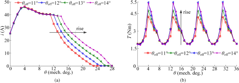
The current and output torques are compared in the Fig. 13 with a fixed turn-on angle θon (−3°) and different turn-off angles. As shown in Fig. 13(a), the interval of the current increases with the increase of θoff, which is beneficial to improve the output torque. As shown in Fig. 13(b), the average of output torque is close to the rated output torque when θoff is 12°. Thus, the optimal turn-on and turn-off angles are −3° and 12° respectively.
Current and output torque versus different θ off when θ on is −3°: (a) Current and (b) Output torque.
Table 3 lists the main parameters of the initial designed machine (SSRM1) and the optimized machine (SSRM2). After optimization, the torque density is improved by about 70%, the torque ripple is reduced by 42%, and the efficiency is improved by 6.26%.
Parameters of two SSRMs
Parameters of two SSRMs
Flux density at aligned position when one phase is excited with 30 A. (a) SSRM1 and (b) SSRM2
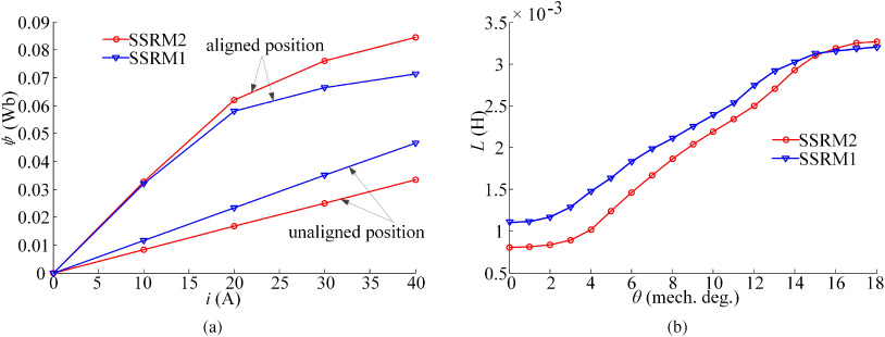
Flux linkage and inductance characteristics of SSRM1 and SSRM2: (a) Flux linkage curves, and (b) inductance characteristics.
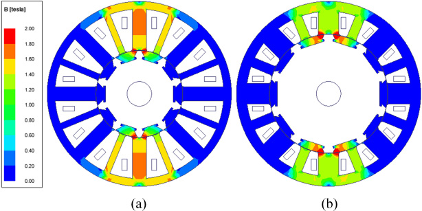
Figure 14 illustrates the flux density of two motors at aligned position when one phase is excited with 30 A. As shown, the two SSRMs have similar flux distribution. At the aligned position, the magnetic flux flows down from the excited stator pole, through the segmented-rotor and returns via the adjacent auxiliary poles. All the conductors in each slot only couple with the flux driven by their phase windings with a few mutual couplings between adjacent slots, which can increase the electrical utilization.
Figure 15(a) shows the comparison of the flux linkage characteristics of the two machines. As shown, compared with the initial design, the flux linkage of the optimized machine at the aligned position is increased and that at the unaligned position is decreased. Therefore, the output torque of the optimized machine will be higher. Figure 15(b) shows the comparison of the inductance for the two machines with the same excitation current (10 A). As shown, the maximal inductance of SSRM2 (after optimization) is higher than that of the SSRM1 (initial machine), and the minimal inductance of the SSRM2 is much lower than that of the SSRM1. The L max∕L min of the SSRM2 and SSRM1 are 4.084 and 2.918, respectively. Thus, the L max∕L min of the SSRM has been increased by 39.96% after optimization. Therefore, the output torque of SSRM2 should be higher than that of SSRM1, which will be confirmed in Fig. 16.
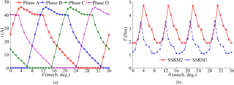
(a) Current of SSRM2, and (b) Output torque comparison.
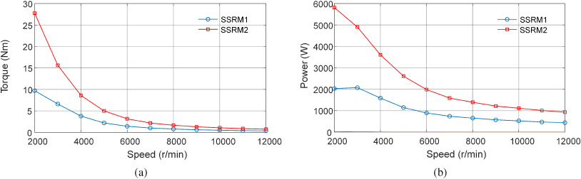
(a) Torque and (b) power versus speed characteristics.
Figure 16(a) illustrates the current waveform of SSRM2 operated at the rated speed. As shown, the current waveform is a standard waveform under the angle position control and the target of optimization is achieved. The output torque waveforms of SSRM1 and SSRM2 are compared in Fig. 16(b). As shown, the output torque of the optimized machine (SSRM2) is significantly higher than that of SSRM1. The average output torque of SSRM2 is 2.941 Nm, which is slightly higher than the requirement and greatly higher than that of the initial SSRM1.
In addition, for further comparison, the torque and power versus speed of the two SSRMs under the same condition are carried out, as shown in Fig. 17. It can be seen that the SSRM2 can provide more torque and power under the whole speed range. The power generation performances of the two SSRMs under braking mode are shown in Table 4. It can be seen that the SSRM2 can provide higher generated power and efficiency than the SSRM1.
Power generation performance of two SSRMs
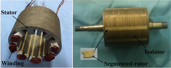
The prototype.
Test platform for the static characteristics of SSRM2.
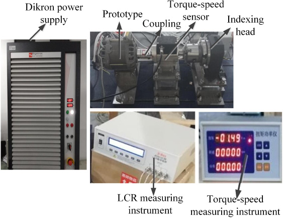
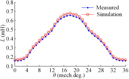
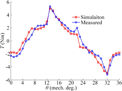
To illustrate the effectiveness of the design and optimization methods for the SSRM, a prototype of the optimized motor (SSRM2) is fabricated with the obtained optimal parameters. Figures 18 and 19 show prototype and the test platform for the static characteristics of the prototype, respectively. As shown in Fig. 19, phase A of the prototype is connected to the LCR measuring instrument. In the measurement, 37 inductance values are obtained by fixing indexing head from 0 to 36 degrees with step size of 1 degree. Similarly, the torques are measured by the torque-speed sensor and torque-speed measuring instrument. Figure 20 shows the measured and simulated phase inductance. Figure 21 shows the measured and simulated torque when phases A and B are excited by 20 A. As shown, there are only small differences between the measured and simulated values. In the measurement of static torque performance, the shaft is locked by the indexing head. Since it hardly for the indexing head to completely lock the shaft, the measured values of torque are slightly influenced, which illustrates the main error between the values of simulation and measurement in Fig. 21.
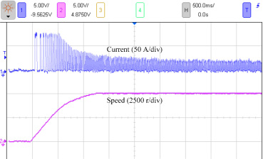
Figure 22 shows the test platform for the dynamic characteristic experiment of the prototype. Figure 23 shows the experimental results for the startup performance. The voltage is 60 V and the load torque is 1 Nm. The rise-up time is about 1.3 s and the steady speed can finally reach over 5000 r/min.
Comparison of static inductance between test and simulation.
Comparison of static torque between test and simulation when the phases A and B are excited by 20 A.

Test platform for the dynamic characteristics of SSRM2.
Figure 24 shows the current and torque curves with CCC mode at 600 r/min and APC mode at 3000 r/min, respectively. The turn-on and turn-off angles are with the optimal values (−3° and 12°), respectively. The reference chopping current in CCC is 75 A and the average torque under this operation is about 25 Nm. The measured average current and torque with APC mode at 3000 r/min are about 25 A and 8 Nm, respectively. Figure 25 shows the measured and simulated output torque of the prototype at the rated speed. As shown, the maximum error between them is 5.03%. Therefore, the applied analysis method and simulation results are credible, and the optimized motor (SSRM2) can meet the design requirement to realize the normal operation.
Current and speed curve during startup.
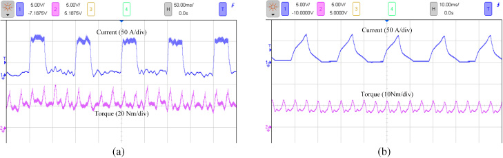
Torque and current curve of phase A: (a) CCC mode at 600 r/min, and (b) APC mode at 3000 r/min.
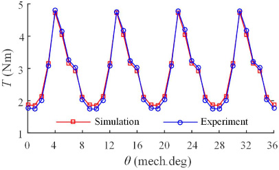
Output torque comparison of the experimental and simulation results.
This paper investigated the detailed design, optimization, and analysis of a new SSRM used as BSG in HEVs. The steady-state and dynamic performances of the initial machine are analyzed by FEA. The initial design cannot meet the requirements of BSG, and thus an optimization method is presented to further improve the output torque and other objectives to meet the design requirements. Then, the performances of the SSRM before and after optimization are compared by simulation. It is found that the SSRM after optimization exhibits better static characteristics, such as better flux linkage and higher static torque, torque ripple, and higher dynamic torque and efficiency. Besides, it also exhibits higher output power and efficiency under the generator mode. Finally, test platforms for both static and dynamic performances of the optimized SSRM are established. The SSRM exhibits good startup performance, and it can operate under CCC at the low speed and under APC at the high speed. Besides, good alignments between the measured and simulated results like inductance, torque and efficiency, verify the accuracy of the analysis method.
Footnotes
Acknowledgements
This work was supported by the National Natural Science Foundation of China under Projects 51875261, 51875255, U1664258, and U1762264, the Natural Science Foundation of Jiangsu Province of China under Projects BK20180046, BK20170071, and BK20180100, the “Qinglan project” of Jiangsu Province, the Key Project of Natural Science Foundation of Jiangsu Higher Education Institutions under Project 17KJA460005, the National Key Research and Development Program of China under Project 2017YFB0102603, the Six Categories Talent Peak of Jiangsu Province under Projects 2015-XNYQC-003, 2016-GDZB-096, and 2018-TD-GDZB-022, the Development of Strategic Emerging Industries of Jiangsu Province under Project 2016-1094, and the Postgraduate Research & Practice Innovation Program of Jiangsu Province under Project CXLX13_668.