
Abstract
As for the inverse decoupling control system of a bearingless induction motor (BL-IM), in order to eliminate the influence of rotor resistance variation on its control performance, on the basis of the reactive power calculation of torque system, a novel fuzzy model reference adaptive (MRAS) identification method of rotor resistance is proposed. The reference model and adjustable model of instantaneous reactive power are derived in detail. In order to improve the identification performance of rotor resistance, a fuzzy PI adaptive law based on popov super stability theory is constructed. On this basis, a rotor resistance identifier is constructed, and it is used to on-line correct the rotor resistance parameter in the inverse system mathematical model of a BL-IM system. Based on the inverse decoupling control system of a BL-IM, the simulation experimental analysis and verification are carried out. The simulation experimental results have shown that when the proposed identification method of rotor resistance is used, not only the identification- and tracking-speed of rotor resistance can be effectively improved, but also the identification accuracy of rotor resistance can be improved; as for the BL-IM system, after the rotor resistance parameter is on-line corrected, not only the inverse dynamic decoupling control performance can be effectively improved, but also the robustness of BL-IM system to the variation of rotor resistance parameters can be improved.
Keywords
Introduction
The AC motor supported by mechanical bearing is widely used in industrial field, but it cannot meet the needs of high-speed and long time running [1]. Then the AC motor supported by magnetic bearing is widely developed [1–4], but it still has some disadvantages, such as more power consumption of magnetic suspension system, limited critical speed, etc. [1,5–7]. The bearingless motor (BLM) is a new type of AC motor [1,8–15], which is proposed based on the structure similarity between the magnetic bearing and common AC motor stator. Normally, there are two sets of windings in the stator slots, include the torque windings (pole pair number p 1, angular frequency ω1 of current) and the suspension windings (pole pair number p 2, angular frequency ω2 of current), when the pole pair numbers and current frequencies of two sets of stator windings meet the qualification of “p 2 = p 1 ±1, ω2 = ω1”, it can produce electromagnetic torque and controllable magnetic suspension force simultaneously [1,9,11,16–19]. Comparing with the AC motor supported by magnetic bearings, the BLM has many advantages, such as a shorter shaft, a higher critical speed and more compact structure, etc. [1,5,20,21], therefore it has broad application prospects in high-speed motorized spindle drive, centrifugal equipment, large-capacity electromechanical energy storage, military and space fields [1]. In all kinds of BLMs, because of a series of advantages, such as robust rotor structure and larger magnetic suspension force stiffness, the bearingless induction motor (BL-IM) has become a research hotspot [1,5–7,22–28]. The accuracy of BL-IM parameters would directly affect its magnetic suspension control performance. In particular, the rotor resistance parameter has a greater impact on the dynamic decoupling control performance of a BL-IM system. In references [5–7], in order to overcome the influence of rotor induction current, some induction compensation methods for the BL-IM system is proposed, which can effectively improve the magnetic suspension decoupling control performance; however the time-varying characteristics of the rotor resistance in actual operation were not discussed. In the normal operation of a BL-IM system, the motor parameters change with the operating environment. In particular, the rotor resistance is greatly affected by the temperature. This kind of situations would directly lead to the observation error of rotor flux-linkage and then affects the induction compensation effect of rotor windings, which would indirectly affect the computation accuracy of air-gap flux-linkage, and would indirectly affect the dynamic decoupling control performance of a BL-IM system [16,24–26]. Therefore, the research on the identification method of the BL-IM rotor resistance has great theoretical significance.
About the rotor resistance identification of ordinary induction motor, much research progress has been made. In references [29–32], the recursive least squares method is used to realize the rotor resistance identification in steady state; but the least squares method is sensitive to the measurement noise, and the identification error is greater in the large speed-fluctuation case [29]. In reference [32], the extended Kalman filter (EKF) method is used to realize the rotor resistance identification, but the calculation is heavy and the algorithm is complex, and then the EKF identification method is not convenient for engineering application [32,33]. Based on the genetic algorithm and neural network optimization algorithm, an identification method is studied in references [34,35], which can be used for the identification of motor state and parameters, and has strong robustness to noise interference; but their algorithms are also complex and difficult to apply in practice. As for the model reference adaptive (MRAS) identification method, it has the advantages of simple algorithm and easy implementation, and has been widely used in the motor parameter identification of ordinary induction motors. For most of the existing MRAS identification methods, the rotor flux observation model and MRAS theory are combined to identify the rotor resistance and motor speed [30,31,36–40]; among them, a direct calculation method of rotor flux-linkage is studied firstly in reference [39], and then the identification of resistance parameters based on MRAS theory is carried out, and it has the characteristics of small calculation and short adaptation time.
The BL-IM is a new type of AC motor suitable for high speed operation. Aiming at BL-IM system, and according to the effect of rotor resistance on the air gap flux-link of torque system, an rotor resistance identification method based on the magnetic suspension force command is proposed in reference [41], but the identification method can only be applied to the special case that the external radial force load is known. Now, although few studies have been reported about the rotor resistance identification of a BL-IM, some enlightenment can be obtained from the existing rotor resistance identification methods of ordinary induction motor.
In this paper, a BL-IM is taken as the research object. So as to overcome the influence of rotor resistance on the control performance of a BL-IM system, a fuzzy MRAS rotor resistance identification method based on the instantaneous reactive power theory is researched, which can effectively avoid the influence of stator resistance variation and pure integral link on the identification accuracy of rotor resistance. In order to improve the dynamic decoupling control performance of a BL-IM system, the rotor resistance identification method is organically combined with the inverse system dynamic decoupling control method. The simulation results have shown that the proposed identification method has higher identification accuracy and tracking response speed, and can effectively improve the dynamic decoupling control performance of a BL-IM system.
Fuzzy MRAS rotor resistance identification based on reactive power
Mathematical model of the rotor flux-linkage of a BL-IM
As for the torque system of a BL-IM, the rotor resistance can be approximated to a fixed value in a sampling period. In the stationary 𝛼-𝛽 coordinate system, the voltage- and current-model of rotor flux-linage can be expressed as Eqs (1) and (2) respectively.
From Eqs (1) and (2): the voltage-type model of rotor flux-linkage is affected by the stator resistance R s1, moreover the pure integral link will bring about the problems of initial value and cumulative error, which would have an impact on the identification accuracy of rotor flux-linkage especially at low speeds; The current-type model of rotor flux-linkage is applicable in the full speed range, but it is greatly affected by the parameter drifts of R r1, L r1 and L m1, especially greatly affected by the parameter drift of rotor resistance R r1. As for a BL-IM, the variations of these parameters would lead to the observation errors of rotor flux-linkage, include the amplitude- and phase-error. Furthermore, the calculation accuracy of air gap flux-linkage, and the decoupling control performance of a BL-IM system would be affected inevitably.
The BL-IM generally works at high speed. Relatively speaking, the voltage-type model can obtain a relatively higher calculation accuracy of rotor flux-linkage. In order to avoid the influence of stator resistance and pure integral link, and so as to improve the identification accuracy of rotor resistance, based on the calculation method of reactive power of bearingless induction motor [42], a fuzzy MRAS identification method of rotor resistance would be studied in this paper, which is based on the instantaneous reactive power of torque system in the stationary 𝛼-𝛽 coordinate system.
In the stationary 𝛼-𝛽 coordinate system, the stator flux-linkage, rotor flux-linkage and stator voltage equation of torque system can be expressed as follows respectively:
From Eq. (3), the rotor current components can be expressed as follows respectively:
The expressions on both sides of Eq. (10) present two calculation ways of the reactive power. The left side of Eq. (10) is the reactive power expressed by the stator current components and stator voltage components, it does not include motor parameters. The right side of Eq. (10) is the reactive power expressed by the stator current components and rotor flux-linkage components; hereinto, it include motor parameters. On the right side of Eq. (10), the required 𝜓 r1𝛼 and 𝜓 r1𝛽 variables can be calculated from Eq. (2).
Subscripting Eq. (2) into Eq. (10), then following equation can be derived.
Selecting the expressions on the left- and right-side of Eq. (11) as the reference model Q and adjustable model
From Eq. (12), it can be seen that the reference model of reactive power does not contain stator resistance parameter. Therefore, the rotor resistance identification based on reactive power has stronger robustness to the variation of stator resistance. In addition, there is no pure integral operation link in the reference model of reactive power. Naturally, there is no problems of integral initial value and cumulative error caused by the pure integral operation. Therefore, the identification method of rotor resistance based on the reactive power is an effective way to improve the identification robustness of rotor resistance.
Defining the observation error of reactive power as follow:
When the observation error e
Q
equals to zero, in order to make the adaptive mechanism still work, the adaptive law should include an integral unit with memory function. Generally, the adaptive regulation law with proportional integral link is adopted. Then based on Popov’s superstability theory, and according to the instantaneous reactive power of torque system, the adaptive law of the MRAS identification mechanism of rotor resistance can be constructed as follow:
By replacing the rotor resistance parameter R
r1 in Eq. (2) with its observation value
The rotor flux-linkage in the adjustable model of reactive power can be obtained according to Eq. (16). When the observation value
The conventional PI adaptive law in Eq. (15) cannot realize the on-line self-tuning of relevant parameters, which would affect the identification effect of rotor resistance to a certain extent. The fuzzy controller does not rely on the accurate mathematical model of controlled object, and has the advantages of stronger adaptability and robustness. And then, in order to improve the parameter self-tuning ability of the PI adaptive law, during the identification process of rotor resistance based on the reactive power, the fuzzy control technology is used to on-line adjust the k p and k i parameters, and then a fuzzy PI adaptive law is constituted.
The fuzzy PI adaptive law is composed of PI adaptive law and fuzzy controller. The input of the fuzzy controller include the observation error e Q of reactive power and its change rate e Qc ; the output include Δk p and Δk i , i.e. the parameter correction values of PI adaptive law. According to the observation error e Q and its change rate e Qc , and combining the fuzzy control rules, the fuzzy controller produces corresponding fuzzy output that is used to correct the parameters of PI adaptive law in real time.
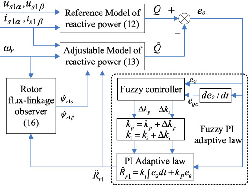
Principle structure diagram of fuzzy MRAS rotor resistance identification method based on reactive power.
Figure 1 gives the principle structure diagram of the proposed fuzzy MRAS rotor resistance identification method that is based on reactive power. In this paper, the error signal e Q between the reference model and the adjustable model of reactive power is taken as the input of fuzzy adaptive law. As for the fuzzy controller, the fuzzy linguistic variables E and E C are obtained by fuzzing the input error signal e Q and its change rate e Q ; and the ΔK P and ΔK I are the fuzzy linguistic variables of the output parameter corrections Δk p and Δk i respectively. The fields of input variables are selected as [−3, 3], the fields of output variables are selected as [−1, 1]. The fuzzy linguistic variables E, E C , ΔK P and ΔK I are all adopt seven fuzzy subset, i.e. [PB, PM, PS, Z, NS, NM, NB]. Where, NB adopts the Z-type membership function, PB adopts the S-type membership function, and other fuzzy subsets adopt the triangular membership functions. The same membership functions are adopted by the fuzzy linguistic variables as shown in Fig. 2.
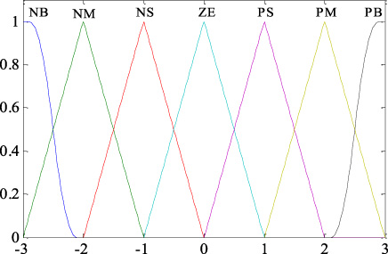
Adopted membership functions.
The fuzzy control rules are a summary of expert knowledge and practical experience. Tables 1 and 2 are the tables of fuzzy control rules formulated for the ΔK P and ΔK I . According to the fuzzy control rules, and by Mamdani fuzzy reasoning method, the fuzzy reasoning results for ΔK P and ΔK I can be derived. Then the defuzzification is carried out by the barycenter method (weighted average method), and then the accurate output of Δk p and Δk i can be obtained. The Δk p and Δk i are used to correct relevant parameters of PI adaptive law in real time.
Fuzzy control rules of ΔK P
Fuzzy control rules of ΔK I
Subscripting (12), (13) into (14), following equation can be derived:
Because the adaptive mechanism adopts a proportional integral form, the whole identification system can be equivalent to an equivalent model composed of a linear time-invariant feedforward module and a linear time-varying feedback module, as shown in Fig. 3.

System equivalent module.
From Fig. 3: the input of feedforward module changes with the feedback module, and there is no external input signal, so the input and output of linear time invariant system can be expressed as “u = ϵ” and “v = Dϵ” respectively. From Fig. 3, following expressions can be obtained:
According to the adopted adaptive law, the identification value
From the Popov hyperstability theory, the following integral inequalities should be satisfied:
Subscripting (18), (19) into (20), then:
In order to make “
For inequality (22), supposing that there is a function f (t), and the function has the first derivative to time.
Then, selecting the function φ1(v, t, τ) to satisfy the following equation:
Then inequality (22) is transformed into the following inequality:
It can be seen that Eq. (26) satisfies the Popov integral inequality. Therefore, the expression of φ1(v, t, τ) can be obtained from Eq. (25) as follow:
For inequality (23), if the integrand on the left side is positive, then Eq. (20) holds when –
By substituting the obtained φ1(v, t, τ) and φ2(v, t) into the Eq. (18), then following equation can be obtained:
By sorting out the above formula, the identification formula of rotor resistance can be obtained as shown in (15), where k p = k 2∕𝜌2, k i = k 1𝜌2. The final adaptive law is a PI controller with initial value. On the basis of PI controller, the system is still stable after the k p and k i parameters are corrected in real time by fuzzy PI control rules. Therefore, the adaptive law of MRAS rotor resistance identifier based on reactive power satisfies the Popov inequality, and the identification system is asymptotically stable.
Setting d−q is the rotor flux orientation coordinate system of torque system. Then the controllable magnetic suspension force components of a BL-IM can be expressed as follows [43]:
Where, K
m
is the magnetic suspension force coefficient, and it can be expressed as follow:
In Eqs (30) and (31): F 𝛼 and F 𝛽 are the controllable magnetic suspension force components along the 𝛼- and 𝛽-coordinate axes respectively; i s2d and i s2q are the stator current components of suspension windings along the d- and q-coordinate axes respectively; 𝜓1d and 𝜓1q are the air gap flux-linkage components of torque system along the d- and q-coordinate axes respectively; μ0 is the air gap permeability, l and r are the length internal diameter of stator core respectively, L m2 is the single-phase excitation inductance of suspension windings, N 1 and N 2 are the effective turn numbers in series of torque windings and suspension windings respectively.
From the mechanical dynamics principle, the radial suspension motion equation of the rotor can be expressed as follow:
Where, m is the rotor mass; f
𝛼 and f
𝛽 are the components of unilateral magnetic pull along the 𝛼- and 𝛽-coordinate axes respectively, and their expressions are as follows:
According to the relationship between air-gap flux-linkage and rotor flux-linkage, the air-gap flux-linkage components of torque system can be obtained as follows [43]:
On the basis of the rotor resistance identification, Fig. 4 gives the schematic diagram of the inverse dynamic decoupling control system of a BL-IM. In Fig. 4:
(1) Connecting the inverse system in series before the original system of a BL-IM [43], then the BL-IM system is decoupled into four second-order pseudo-linear integral subsystems, i.e. the motor speed subsystem, rotor flux-linkage subsystem, 𝛼- and 𝛽-displacement component subsystems. The specific inverse system model of the original BL-IM system can refer to references [43], and no further details are given here.

Inverse decoupling control system of bearingless induction motor based on rotor resistance identification.
(2) Then, each linearized subsystem is equipped with a PD regulator that has a first-order inertial filter, and then the overall control system structure of a BL-IM is constituted.
(3) In order to effectively improve the dynamic decoupling control performance of BL-IM system, the rotor resistance parameters in the inverse system model and rotor flux-linkage observation model are corrected in real time according to the identified rotor resistance values.
To verify the effectiveness of the proposed rotor resistance identification method, a four-pole BL-IM is taken as the controlled object, according to the inverse dynamic decoupling control system structure in Fig. 4, the Matlab/Simulink simulation model is established, and the proposed fuzzy MRAS identification method of rotor resistance is simulated and analyzed in detail. The parameters of a BL-IM are given in Table 3.
Parameters of a BL-IM
Parameters of a BL-IM
Setting of simulation experimental conditions: the initial given signal
Under the given simulation experimental conditions, adopting the proposed fuzzy MRAS identification method based on reactive power, Fig. 5 gives the identification response curves of rotor resistance after the BL-IM system starts. At the same time, in order to facilitate comparative analysis, the identification response curves of rotor resistance are given also when the ordinary PI adaptive law is adopted. From the fuzzy MRAS identification process of rotor resistance shown in Fig. 5, the simulation research results are as follows:
(1) When the ordinary PI adaptive law is adopted, the identified rotor resistance reaches its steady-state value at about 0.65 s, and the overshoot of the identified rotor resistance is about 12.1%.

Identification response curve of rotor resistance.
(2) When the fuzzy PI adaptive law is adopted, the identified rotor resistance can reach its steady-state value within 0.4 s, and the overshoot of identified rotor resistance is about 6.8%. I.e. compared with the case that adopts the ordinary PI adaptive law, the identification response time is advanced by 0.15 seconds, and the overshoot of identification response is reduced by about 5.3%.
(3) The simulation results have shown that when the Fuzzy PI adaptive law is adopted, the identification process of rotor resistance has a faster response speed and a smaller overshoot.

Identification response curve of rotor resistance when the rotor resistance varies.
In order to further verify the identification effect when the rotor resistance changes, the actual value of rotor resistance is increased to 1.5 times at 1.5 s, i.e. the rotor resistance is changed from 1.423 Ω to 2.1345 Ω at 1.5 s, Fig. 6 gives the identification response curves of rotor resistance. From Fig. 6, following simulation research results can obtained:
(1) No matter the fuzzy PI adaptive law or the ordinary PI adaptive law is adopted, the identification value of rotor resistance can be reliably converged to its steady-state actual value, the identification response process has high robustness to parameter variation.
(2) Compared with the case that adopts the ordinary PI adaptive law, if the proposed fuzzy PI adaptive law is adopted, the peak time of the identification response is about 0.05 s ahead of time, and the rotor resistance can reach its steady-state actual value about 0.1 s ahead of time. Therefore, when the proposed fuzzy PI adaptive law is adopted, a relatively faster response speed can still be obtained.
(3) Compared with the case that adopts the ordinary PI adaptive law, if the proposed fuzzy PI adaptive law is adopted, the steady-state identification error of rotor resistance is reduced by about 0.06 milliohm, and a relatively higher steady-state identification accuracy can be obtained.

Rotor flux-linkage response curves before and after the rotor resistance being corrected.

Motor speed response curves before and after the rotor resistance being corrected.
The simulation response waveform of the rotor flux-linkage before and after the change of rotor resistance is shown in Fig. 7, and that of the motor speed is shown in Fig. 8. For the convenience of comparison, the simulation response waveforms before and after correcting the rotor resistance value of the BL-IM inverse system model are also given. From Fig. 7 and Fig. 8, there are following research results:
(1) Due to the change of rotor resistance, the actual rotor flux-linkage also changes accordingly, which results in the fluctuation of observed rotor flux-linkage; After the rotor resistance in the BL-IM inverse system model and that in the rotor flux-linkage observer are real-time corrected, under the action of rotor flux-linkage closed-loop, the rotor flux-linkage can return to its stable state within 0.5 seconds, the steady-state error is less than 1.5%, and then the high precision control of rotor flux-linkage is achieved. On the contrary, when the rotor resistance is not corrected in real time, a steady-state error about 6.7% of rotor flux-linkage is generated.
(2) After the change of rotor resistance, if the rotor resistance is not online corrected, the motor speed shows a weak speed-up trend; although the increase of motor speed is relatively small, the influence of rotor resistance change on the motor speed is obvious. If the rotor resistance is online corrected, the motor speed can quickly return to its previous stable state after a short adjustment process. The simulation results have shown that if the rotor resistance is corrected in real time, the operation control performance of a BL-IM system can be effectively improved.

Response curves of radial displacement before and after the resistance correction.
After the rotor resistance in the inverse system model and that in the rotor flux-linkage observer are online corrected, the response waveforms of radial displacement components and those of magnetic suspension control current components are given in Figs 9 and 10 respectively. In order to facilitate comparative analysis, the response waveforms of relevant variables without rotor resistance correction are also given.
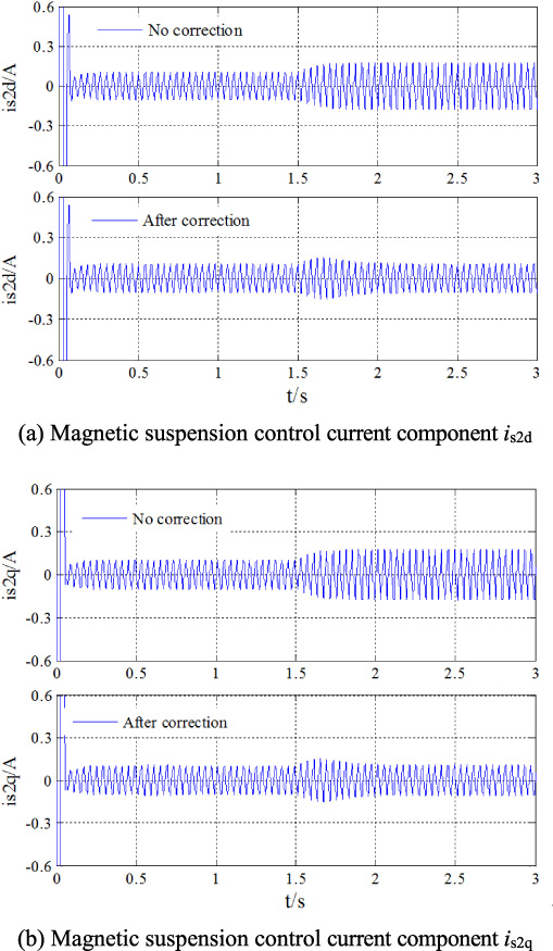
Response curves of the suspension current before and after rotor resistance correction.
From Figs 9 and 10, there are following research results:
(1) After the change of rotor resistance, if the rotor resistance parameter is not corrected in real time, the inaccuracy of observed rotor flux-linkage leads to that of air-gap flux-linkage, the decoupling control performance between the 𝛼- and 𝛽-displacement components is decreased, the fluctuation amplitude of the 𝛼- and 𝛽-displacement components increases by about 50%, and then the magnetic suspension control accuracy of the rotor is seriously decreased. At the same time, the amplitude of the magnetic suspension control current is increased by about 50%.
(2) After the rotor resistance parameters in the inverse system model and rotor flux-linkage observer is corrected in real time, the 𝛼- and 𝛽-displacement components can return to their stable state within 0.5 s after a short adjustment process, and the magnetic suspension control accuracy of the rotor is basically the same as that before the change of rotor resistance. Similarly, after a short adjustment process, the magnetic suspension control current can return to its stable state within 0.5 s, and the amplitude of the magnetic suspension control current is basically the same as that before the change of rotor resistance.
(3) The simulation results have shown that after the rotor resistance parameter is identified and corrected in real time, not only can the steady-state magnetic suspension control accuracy of a BL-IM system be improved effectively, but also the stability and the robustness to the variation of motor parameters can be effectively improved.
In order to eliminate the influence of rotor resistance on the control performance of a BL-IM system, on the basis of inverse system decoupling control, a fuzzy MRAS rotor resistance identification method based on the reactive power is proposed. Firstly, in the stationary 𝛼-𝛽 coordinate system, the reference model and adjustable model of reactive power are derived in detail. Then, in order to improve the parameter self-tuning ability of the adaptive law, the fuzzy PI adaptive law based on the Popov superstability theory is constructed, and by fuzzy control technology, the k p and k i parameters in PI adaptive law is real-time adjusted. At the end, in order to improve the dynamic decoupling control performance of the BL-IM inverse system, the rotor resistance parameter in the inverse system model and that in the rotor flux-linkage observation model are corrected in real time according to the identified rotor resistance value.
According to the MRAS identification algorithm of rotor resistance and the simulation experimental results of a BL-IM system, the following research conclusions can be obtained:
(1) When the rotor resistance is MRAS identified according to the adjustable- and reference-model of reactive power proposed in this paper, whether the proposed fuzzy PI adaptive law or the PI adaptive law is adopted, the identification value of rotor resistance can reliably converge to the steady-state actual value, and the BL-IM system has high stability and robustness to the parameter variation.
(2) Adopting the proposed fuzzy MRAS identification method of rotor resistance based on the reactive power, not only can the identification and tracking speed of rotor resistance be effectively improved, but also the steady-state identification accuracy of rotor resistance can be effectively improved.
(3) After the proposed “fuzzy MRAS identification method of rotor resistance based on reactive power” is combined with the inverse dynamic decoupling control method, by real-time identifying and tracking the rotor resistance parameter, and by real-time correcting the value of rotor resistance in the inverse system model and that in the rotor flux-linkage observer, the dynamic decoupling control performance and steady-state magnetic suspension control accuracy of a BL-IM system can be obviously improved; at the same time, the amplitude of the steady-state magnetic suspension control current can be obviously reduced.
(4) The proposed fuzzy MRAS identification method of rotor resistance based on reactive power in this paper is effective and feasible.
As for a BL-IM system, the reference model of reactive power presented in this paper does not include the stator resistance parameter and pure integration, so the influence of stator resistance and pure integral link on the identification accuracy of rotor resistance can be effectively avoided; this is a significant characteristic or advantage of the proposed identification method. Secondly, by combing the proposed fuzzy MRAS identification method based on reactive power with the analytical inverse decoupling control method, the problem that the analytical inverse dynamic decoupling control performance of a BL-IM system depends on the accuracy of motor parameters is effectively overcome, thus a useful idea for the high performance dynamic control of a BL-IM system is provided. Thirdly, the fuzzy control technology is used to improve the adaptive law of MRAS identification method in this paper, which effectively improves the identification response speed and steady-state identification accuracy; while there should exist other better ways to improve the parameter self-tuning ability of adaptive law, this is also the problem to be explored in the future.
Footnotes
Acknowledgements
The support of the National Natural Science Foundation of China (51277053) and the Key scientific and technological project in Henan province (202102210095) is acknowledged.