



Abstract
As a renewable energy, ocean wave energy is exploited with infinite potential to solve the energy crisis. In this study, we develop a novel two-body direct-drive wave energy converter (DD-WEC) to surmount the problems associated with low power density, low direct-drive speed of the buoys, seawater corrosion and maintenance in the existing two-body WEC. Its prototype consists of two cylindrical buoys that float horizontally at sea level and the Halbach permanent magnet linear generator (HPMLG) that is employed in the power take-off (PTO) system. The energy is extracted from the relative motion between two buoys oscillating. Compared with the existing WEC, the proposed WEC has more vigorous motion between buoys, higher conversion efficiency and little extra underwater structure, due to the utilization of the horizontal buoys and the HPMLG. First, the motion equations of buoys are derived on the basis of linear wave theory. And depending on the motion equations, the structure of buoys and the HPMLG is designed. And we found that compared with the existing WEC, the proposed WEC has more vigorous motion between buoys in the seawater waves oscillation. Then, based on finite-element method (FEM), the performance of the HPMLG is evaluated, and it can generate 19% more power than the traditional permanent magnet linear generator (TPMLG) based on the same wave motion. Finally, the DD-WEC prototype is manufactured based on the designed parameter. The manufactured prototype is tested in the test platform and the wave tank. The measured output voltage is highly consistent with the observed variation trends in FEM simulation data. The results show that the proposed DD-WEC is well suited for wave energy conversion.
Introduction
In recent years, non-renewable energy like oil, natural gas and coal will be exhausted in the near future due to the increasing costs by human beings, many renewable energy sources have been developed, such as wind, geothermal, and solar energy, which have been well established and optimized within industry manufacturers [1,2]. In particular, ocean wave energy [3,4] has huge potential to exploit as a kind of clean, pollution-free and renewable energy.
In order to absorb wave energy and convert it to electricity, research on wave energy converters (WECs), such as Oscillating Water Column devices [5–7], Overtopping devices [8–10] and Oscillating body devices [11–13], have been being carried on since 1970s [14]. Most of them employ the complex mechanical structure as their power take-off (PTO) system, such as gearboxes, hydraulic or pneumatic systems [15]. However, the mechanical interfaces have the disadvantages of complicated mechanical structure, low conversion efficiency, poor impact corrosion resistance, etc [16]. In recent years, direct-drive wave energy converter (DD-WECs) [17,18] which is aimed at improving conversion efficiency and stability have attracted attention to many researchers. DD-WECs can directly convert mechanical energy into electrical energy with no intermediate steps between the primary interface and the electrical machine by using a linear generator [19].
A variety of DD-WECs have been developed for extracting wave energy. The first DD-WEC was the Archimedes wave swing (AWS) [20]. A floater is completely under water and connected to translator of the linear generator which is placed in a chamber of compressed air mounted on seabed. The waves move the floater vertically with respect to the fixed lower part that leads to converting wave energy to electrical energy. A prototype of the AWS was deployed and tested at the northern coast of Portugal in the second half of 2004 [21]. Moreover, Waters et al. [22] developed another DD-WEC floats at sea level whose body is connected to the linear generator installed on the seabed by chain. The oscillating body drives the generator to generate electricity. Its prototype was installed at a depth of 25 mm, 2 km off the Swedish west coast in the proximity of Lysekil.
However these single-body DD-WECs have some problems like mooring, seawater corrosion, and access for maintenance. To eliminate them, two-body DD-WEC was designed. Two-body DD-WECs consist of a heaving buoy and a submerged buoy, which are statically suspended in water. The two-body DD-WECs extract the energy from the relative movement between two bodies oscillating differently [23]. The hydrodynamic characteristics of the two-body DD-WEC in the frequency and time domain were theoretically analyzed in detail by Engstrom et al. [24].
In fact, low power density is one of disadvantages of existing two-body DD-WECs owing to the low direct-drive speed of the buoys. In order to enhance the power density and the relative speed of the buoys, we tentatively put forward a novel two-body DD-WEC as an alternative. Unlike the existing two-body DD-WEC, the proposed one purposely utilizes the cylindrical bodies that float horizontally at sea level, and a HPMLG is employed in the PTO system. The proposed WEC is much like Pelamis [25], but its structure is simple without intermediate complicated hydraulic systems. Although the energy is also extracted from the relative motion between two bodies oscillating, the motion of the cylindrical bodies that float horizontally at sea level is more vigorous than the motion of the bodies in the existing two-body WECs. The Halbach permanent magnet linear generator (HPMLG) PTO system improves the power density, decreases the weight of translator and the cogging force of linear generators compared with traditional permanent magnet linear generator (TPMLG) [26–28]. In addition, the structure of the entire proposed WEC floats at the water level, and has little underwater parts. Therefore, it is easy to be repaired. This paper is devoted to study the fabrication and test the feasibility of this DD-WEC prototype.
The remainder of this paper is organized as follows: In Section 2, the two-body DD-WEC in this paper is simply explained, and the motion equations of the buoys are analyzed. In Section 3, the design of buoys is described. In Section 4, and the performances of the HPMLG are illustrated. In Section 5, a prototype is manufactured. HPMLG is measured in the test platform and the proposed DD-WEC is tested in the wave tank. Finally, the conclusions are provided in Section 6.
Two-body DD-WEC structure and analysis
Two-body DD-WEC structure
The proposed two-body DD-WEC, shown in Fig. 1(a), is composed of two same cylindrical buoys, a HPMLG and linear slides. A HPMLG PTO system is employed, whose secondary is fixed on a buoy’s lateral surface and the primary is fixed on the other buoy’s lateral surface. Linear slides are also installed on the two ends of buoys’ lateral surface. As illustrated in Fig. 1(b), two bodies float at sea level and are driven to oscillate in the vertical (z) direction through linear slides by the wave. h is water depth, 𝜆 is the wavelength, z A and z B are buoy A and buoy B vertical displacement, H is the wave height. The length L of the buoys is less than the wavelength 𝜆 that causes a phase difference between buoy A and buoy B . Then, a relative movement between the HPMLG primary and secondary is produced, and the relative motion between the two buoys could induce a voltage in the coils. The direct-drive speed can be higher due to the utilization of two horizontal bodies, because the relative motion between two horizontal bodies on the wave could be more vigorous. The system is also equipped with end stop springs to protect it from mechanical shock loads in waves, when the wave height is too high.
The proposed two-body DD-WEC utilizes the horizontal cylindrical buoys as the oscillating bodies, but the existing two-body WEC employed the vertical cylindrical or spherical buoys [29–31]. And the existing two-body WEC is either up-down structure [29,30] or internal and external structure [31]. For the proposed WEC, because the length L of the buoys is less than the wavelength 𝜆 that causes a phase difference between buoys, the relative motion between buoys is more vigorous than existing two-body WEC within a the seawater waves oscillation. The frequency domain is determined by the length of the buoys.

(a) Structure of the proposed WEC, (b) motion diagram of the oscillating buoys in the wave.
In order to derive the motion equation of the two-body DD-WEC, some assumptions are taken into considerations:
The fluid is non-viscous and irrotational. The motion equations are based on linear wave theory [32]. All buoys oscillate only in the vertical direction, and other degrees of freedom are neglected. The width of the buoys is far less than the width of wave. The radiation damping force is ignored. The HPMLG is modeled as a viscous damper.
As shown in Fig. 2, according to the force analysis of the buoys, dynamic equations can be expressed as:
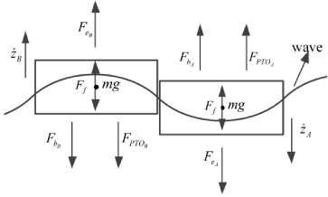
Schematic diagram of buoys force analysis.
Under regular waves, wave force of buoys in the linear wave can be represented as follows:
The electromagnetic damping force is considered linear and proportional to the relative velocity of the buoys but with the opposite direction [34]. The expressions of electromagnetic damping force are:
Take Eqs ((3)) and ((4)) into Eq. ((2)), Eq. ((2)) may then be re-written as
Proper dimension of the oscillating buoys helps to capture energy from the wave. The buoys are designed as a cylinder that floats horizontally at sea level in Fig. 3. The buoy is constructed of ultra-high molecular weight polyethylene (UHMWPE) to provide extra buoyancy. The magnetic materials should not be applied to the structure of the buoy. Because the HPMLG generates electricity according to the Faraday’s law of induction, and the magnetic materials can possibly interfere with the magnetic field lines generated by the Halbach array. In addition, magnetic materials are easy to corrode in salt water. However, UHMWPE does not corrode in salt water, and have a good impact resistance making it a prime material for DD-WEC. The HPMLG translator and primary are installed on a buoys’ lateral surface, respectively. According to the experimental environment (stated in the Section 5.2) and the dimension of HPMLG (stated in the Section 4), the diameter of buoys is designed as 0.5 m.
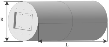
Schematic structure of the buoy.

Compassion the maximum speed of two WECs (P-WEC is the proposed WEC, E-WEC is the existing WEC).
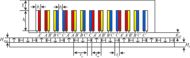
The two-dimensional structure of the HPMLG.
The WEC in this paper is a two-buoy system, buoys’ relative motion causes a relative movement between the HPMLG primary and secondary that successively generates electricity. The average absorption power extracted from the HPMLG can be calculated by the time average of the instantaneous power:
The proposed two-buoy DD-WEC extracts wave energy from the relative motion between two buoys oscillating. In order to maximize the time average of the instantaneous power, the relative velocity of motion between buoys is maximized in the case that the HPMLG damping coefficient is not changed. According to the Eq. (9), the absolute value of the relative speed between buoys can be expressed by:
According to the equation ((10)), the value of the relative speed between buoys attains its maximum, when
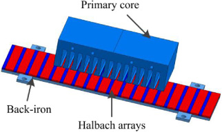
The schematic structure of the HPMLG.
Main parameters of the proposed DD-WEC

Arrow plot of magnetic flux density under two cases. (a) The tooth faces the main magnet, (b) The slot faces the main magnet.
HPMLG which is fixed on a buoys’ lateral surface between buoys consists of two components: primary and secondary; the former includes primary core and winding, and the latter includes flat Halbach permanent magnet arrays and back-iron. As indicated in Figs 5 and 6, the HPMLG primary is facing the secondary, thereby providing a path for the flux to flow in. When the buoys are in a straight line, the primary is in the middle of primary. The HPMLG primary and secondary had a relative motion leading to the electric power generation by linear slides in wave. The HPMLG primary winding adopted the structure of 8 poles and 12 slots depending on the diameter of buoys and Halbach permanent magnet arrays for more electricity generated.
In order to provide a strong magnetic field, the permanent magnet NdFe35 is adopted in HPMLG for its relatively higher coercivity and remanence. The material of primary core and back-iron is made of silicon lamination D23, which is a kind of commonly used magnetic material with many advantages such as low cost and relatively high saturation point. The HPMLG primary and secondary covered by the rubber are isolated from the sea water. The main design parameters of the proposed DD-WEC are given in Table 1.
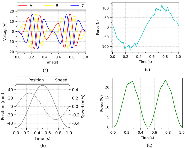
Output performance under rated load (a) Output voltage, (b) Speed and displacement of the HPMLG secondary, (c) Electromagnetic force, (d) Output power.

Two types of permanent magnet linear generator (PMLG) (a) HPMLG, (b) TPMLG.

Comparison of two linear generators the on-load output voltage, (b) Output power at different loading resistances.

Manufactured the proposed two-body DD-WEC prototype (a) The cylindrical buoy, (b) The HPLMG secondary and primary.
Based on the geometric parameters of the HPMLG shown in the Table 1, the COMSOL Multiphysics package has been used to construct a finite element model of the HPMLG. The finite element method (FEM) is used to solve Maxwell’s equations.
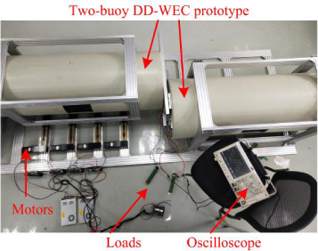
The prototype of two-buoy DD-WEC in the test platform.
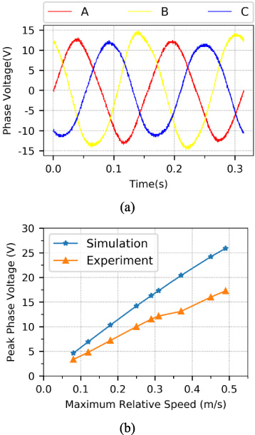
Measured in the test platform. (a) Three-phase output voltage under load at constant speed of 0.37 m/s, (b) Single-phase output voltage under load at different constant speed.
Figure 7 illustrates the arrow plot of magnetic flux density distribution in the cross section of the HPLMG. We observed that in the case where the tooth faces the main magnet, magnetic flux density of the tooth is highest, around 0.85 T, and magnetic flux density of teeth on both sides of that are about 0.32 T and 0.54 T, respectively. In the other case where the slot faces the main magnet, the magnetic flux mainly goes through two teeth on both sides of the slot, with flux density of about 0.54 T and 0.27 T, respectively.
Load performance analysis of HPMLG
The relative displacement between HPMLG secondary and secondary is z
A
− z
B
= 0.05cos(2πt+π), and the HPMLG primary is still. Figures 8a–d illustrate the output voltage, HPMLG secondary displacement, electromagnetic force and power under a load of 20 Ω. As is shown in Fig. 8, the three-phase output voltage matches the inverter waveform of the three-phase linear generator, then, the electromagnetic force, the HPMLG secondary speed and the power are almost consistent with the equation;
To show the advantages of the HPMLG with more power density, it is compared with the TPMLG by using FEM simulation. As shown in Fig. 9, two generators have the same machine parameters, including pole pitch, the length, width and thickness of the PMs, air gap, and turns of coils, as well as same material performance. Figure 10a shows the on-load voltage of the phase A at a speed of 0.5 m/s by FEM. It can be seen the output voltage of the HPMLG is more than the TPMLG. Figure 10b shows the average output active power under different resistances, when the motion of the HPMLG secondary is z A − z B = 0.05cos(2πt + π). As shown in Fig. 10b, the HPMLG and TPMLG both tend to increase first and then decrease as the load increases and they both attain their maximum average power in the case that the load is about 11 Ω. However, the HPMLG can generate 19% more power than the TPMLG. Therefore, the utilization of the HPMLG can effectively increase the power density.
As shown in Fig. 11, a prototype of two-body DD-WEC proposed in this paper was fabricated, whose detailed key dimension parameters are designed depending on Table 1.
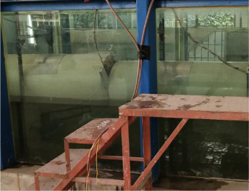
The test on the prototype in the wave tank.
The wave parameters
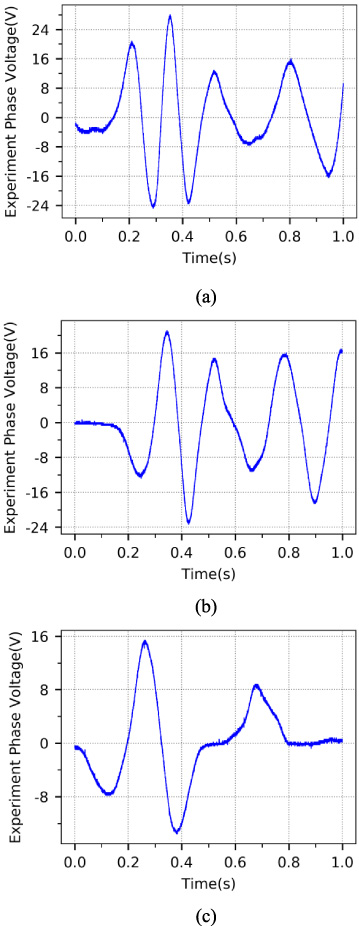
The no-load single-phase output voltage tested in the wave tank (a) T = 1.4 s, H = 0.12 m, (b) T = 1.4 s, H = 0.1 m, (c) T = 1.6 s, H = 0.1 m.
When the prototype is manufactured, the performance of the proposed HPMLG is measured on the test platform. The test platform consisted of four motors, four crankshafts connecting rods, prototype, oscilloscope, loads and some aluminum frames, etc. The ocean wave is a linear motion while the motor is rotary. In order to convert the motion to linear movement, crankshafts with a stroke of 0.4 m was used to connect the proposed DD-WEC and motors. Furthermore, the velocity of the driving motors is too high to simulate the actual ocean wave motion, and only one of the buoys on the test platform makes linear motion, the other buoy is stationary. Therefore, the relative speed between the buoys is replaced by a single buoy’s speed, which also can analyze the performance of the proposed HPMLG, and the one of buoys makes linear motion at different constant speeds. Figure 12 shows the prototype of two-buoy DD-WEC is tested on the test platform.
The measured three-phase output voltage waveforms on the test platform at constant speed of 0.37 m/s with three-phase symmetrical resistance load of 20 Ω are given in Fig. 13a. It can be found that the three-phase output voltage of the HPMLG varies sinusoidally with time and the value of the three-phase output voltage is almost same. Figure 13b shows the variation of the experiment and simulation output voltage with different constant speed at resistance load of 20 Ω. According to Fig. 13b, when the damping is same, the DD-WEC can generate more electrical power with a higher relative speed between buoys, and the output voltage of the simulation and experiment are both proportional to the speed of the buoys. The measured output voltage is almost 70% of the calculated value in the FEM simulation. Because the FEM calculation is carried out under ideal conditions, ignoring various factors such as linear slides friction, churn loss and stray loss [36,37]. In addition, the performed FEM simulation was 2D one, whereas a more accurate representation of the structure would require a 3D geometrical model to take into consideration for the final effect. Under the premise of neglecting the above factors, the measured peak output voltage values have an agreement with the FEM results.
Test in the wave tank
After the HPMLG tested, the tests of the proposed D-D WEC were conducted in the wave tank to verify its conversion performance based on the wave motion, as shown in Fig. 14. The length, depth, and width of wave tank are 50 m, 1 m and 1 m, respectively. From a wave maker at the end of the tank, monochromatic waves with a given wave height and wave period are produced to simulate the ocean waves. And the wave maker can simulate different monochromatic waves in each experiment. The designed D-D WEC floats horizontally at the water level. And two tensioned moorings shackle on the one of the buoys’ lateral surface. Incident ocean waves drive the buoys to move in the vertical direction with a phase difference, causing a relative movement between the HPMLG primary and secondary fixed on a buoys’ lateral surface between buoys.
In each experiment, monochromatic waves with a given wave height and wave period are made in the wave tank. Because the length of the buoys in this paper is designed as 1.35 m, which is based on T = 1.4 s. We choose the test conditions according to the designed period of 1.4 s. The selected wave heights H and periods T were listed in the Table 2. Figure 15 shows the single-phase no-load output voltage waveforms with three sets of H and T listed in the Table 2. When T = 1.4 s, H = 0.12 m and T = 1.4 s, H = 0.1 m, the DD-WEC dose oscillate most violently with T = 1.4 s, and achieves the peak value 28 V and 21.12 V. And when T = 1.6 s, H = 0.1 m, the single-phase output voltage is less than the case that T = 1.4 s. But the phase voltage waveform is consistent with the simulation. Therefore, from the experimental results, the design of the proposed WEC is feasible.
Conclusions
In order to reduce the problems in the existing two-body DD-WECs, a novel WEC is proposed in this paper. In this system, the problems associated with low power density, low direct-drive speed of the buoys, seawater corrosion and maintenance have been largely decreased. A detailed description about the DD-WEC is presented. The structure of the DD-WEC is designed on the basis of motion analysis of the two buoys completely, and the design process of the DD-WEC is stated in detail. The output performance of the DD-WEC is evaluated by using FEM. According to the design parameters, a prototype is manufactured. The output performance of the DD-WEC is measured in the test platform and the wave tank. The analysis of the proposed WEC verified that the buoys’ direct-drive speed of the proposed two-body WEC is much more than the existing two-body WEC within the seawater waves oscillation. According to the simulation results of the FEM, the HPMLG can increase the power density and generate 19% more power than the TPMLG. The results tested in the platform are almost 70% of the calculated value in FEM simulation and have a good agreement with the observed variation trends in FEM simulation data. The results tested in the wave tank show that the proposed WEC is feasible and suitable for wave energy conversion. Future work will be focused on the structure optimization and control of the proposed DD-WEC.
Footnotes
Acknowledgements
This work was funded by a project that partially funded by National Science Foundation of China (51675265) and the Priority Academic Program Development of Jiangsu Higher Education Institutions (PAPD). The authors gratefully acknowledge this support.