
Abstract
In electric motorcycles and light electric cars, permanent magnetic synchronous motor (PMSM) of outer-rotor type are preferred, due to its concise structure and flexible control. Since the body mass and road impact causes vertical eccentricity on shaft bearings, vibration and noise take place during vehicle cruising along with a torque and speed ripple. The torque ripples contain significant features closely related to eccentricity, and those special components can be compensated by an injection current with proper frequency, phase and amplitude. In this paper, a novel control method is used to regulate the injection current to restrain torque ripples. By coarse turning with quadratic spline curve fitting and fine turning with successive approximation, the method can response sudden disturbance and drive the specific torque ripple to minimum in a very short time, so that the performance on ride comfort and handling stability of the vehicle could be improved. Experimental tests show that the method performs favorably with rapid convergence and validity.
Keywords
Introduction
In-wheel PMSM is considered to be the next generation of propeller for the light-duty electric cars, as it has higher efficiency, simpler mechanism, and more flexible control. In hub actuated vehicles, the propulsive force is generated from the four driving wheels and coordinately controlled by electronic control units (ECUs), so that the vehicles achieve high driving flexibility and transmission efficiency. However, the driving wheel combines with IWM as a rigid body under the suspension system, which may support car load and suffer severe impact from the rough pavement. As a result of mass load and road impact, the bearing of IWM deforms in vertical direction and appears eccentricity between inner stator and outer rotor. This fault leads to problems with additional vibrations, noises, and torque pulsations, which are harmful for motor efficiency and its lifetime [1,2]. In addition, the torque vibrations may deteriorate performances on ride comfort, and more seriously, loss traction control [3–6]. Therefore, in crucial EV applications it is essential to suppress the torque ripples for better performance of stability and safety.
Recently, some analyses on torque vibrations of PM motor with respect to rotor eccentricity have been reported. As studied in [7,8], the high order harmonics of electromagnetic torque are due to the combined reaction between stator currents in three symmetric windings and the distorted flux in the airgap. The quantitative relationship between fundamental and harmonic components under eccentric condition is studied in [9,10]. In [9], the static eccentricity can be derived from a frequency spectrum diagnosis of the stator current. The amplitudes of sideband components in the frequency pattern are introduced as proper indices. By comparison of indices between eccentric and other faults at particular frequencies, it is possible to determine the occurrence, as well as the type and percentage of the eccentricity. In [10], the experimental results indicate that the eccentricity-related indices at specific frequencies are not under influence of load variations, which can be utilized as a competent criterion for eccentric fault recognition.
The feature of torque ripples is consistent due to the structure of PMSM under static conditions, and the fractional slot-pole design [11], multilayer winding design [12] and rotor shape optimization [13] methods are normally adopted to suppress inherent torque ripples of the motor. For in-wheel-motor-driven vehicles, when running on complex roads the eccentric degree of the motor is changing dynamically, so that the structural-based methods mentioned above are not working properly. Therefore, harmonic current injection methods are preferred to suppress instantaneous torque ripples caused by rotor eccentricity. As studied in [14–21], these control-based methods generally consist of two consecutive procedures: the harmonic torque extraction and the injection current control. In some electrical model based methods, the torque harmonics are extracted from electrical variables such as stator currents [14], non-ideal back EMF [15], self-/mutual- inductances [16] and calculated torque [17], while in other mechanical model based methods are extracted from dynamic speed fluctuation of the motor [18]. By Fourier transformation or Park transformation with notch filter, those extracted harmonic signals can be transferred into current regulators as control references, for undesired torque ripple suppression. In order to achieve quick response of the current regulator, reference [19] employs simple PI controllers to regulate injection current of each order respectively, but it requires intensive computation burden to perform transformations and low-pass filters beforehand, and the cut frequencies of filters may be difficult to turn. Instead of PI controllers, [20,21] have proposed simple regulation methods like Minimum Ripple Point Tracking (MRPT) and Gradient Descent Optimization (GDO) algorithms, to determine optimal amplitude of injection current by iteration. The MRPT method uses fixed step size to iterate the injection current, and the torque converges to the minimal point gradually. The GDO method considers gradient of the torque function at each iteration moment, and adjusts the step size of current according to the gradient. However, the convergence rates of those current regulation methods are highly dependent on iterative parameter settings, and the control system may not response in time under high dynamic conditions. Therefore, a novel current regulation method considering both simplicity and fast convergence, called Minimum Amplitude Point Tracking (MAPT), is put forward in this paper. An important feature of the proposed method is that, unlike aforementioned approaches, it is not sensitive to iterative parameters and the number of iterative steps is limited. Meanwhile, hard calculations like high-order filtering, matrix prediction or state observation are not required.
In this paper, the mechanism of electromagnetic torque ripples is analyzed and the relationship between rotor eccentricity and torque harmonics are derived in Section 2. Then in Section 3, a harmonic current injection process based on an implanted circuit, which is independent from three-phase stator windings, is proposed to suppress torque ripples using MAPT control method. In Section 4, experimental results are given to show the effectiveness of the proposed algorithm under different conditions. The final section concludes the performance of the method.
Torque ripple analysis
Rotor eccentricity of the in-wheel motor
A schematic diagram of vertical load analysis on the shaft of the in-wheel motor is shown in Fig. 1.
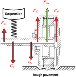
Vertical force analysis of in-wheel motor.
From the figure above, the vertical forces are applied on both sides of the end covers, and generate elastic deformation on two bearings. The static force equilibrium on the shaft is met according to (1). The Young’s Modulus E represents the elastic performance of the bearing steel, so that the whole strain can be described as (2)
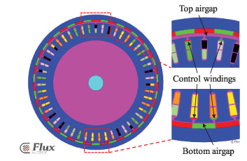
In Fig. 2, the bearing deformation, though to a very tiny extent, results in a static vertical airgap eccentricity between out rotor and inner stator. As shown in [1], the unbalanced tangential magnetic force caused by airgap eccentricity has some negative influence on ride comfort and handling stability of the vehicle, for instance, with 5.13% increment in body vibration acceleration and 4.3% increment in body pitch angle acceleration.

Rotor and airgap static eccentricity in-wheel motor.
For a faulty PMSM especially with rotor eccentricity, the permeability in the distorted airgap is approximately equal to vacuum, the magnetic flux density is inverse proportional to radial length of the airgap. Therefore, the distortion factor can be defined as
The mathematical model of the in-wheel motor is usually described in synchronous dq reference frame. The voltage equation and electromagnetic torque may be expressed as (9) and (10) Low harmonics in stator current, Unsaturated magnetic flux, Well-designed slot/pole combination, Concentric rotor with perfect airgap.
For outer rotor PMSMs with large rotary moment of inertia, the torque ripples act less obviously on the speed. Generally, the high-order cogging torque ripple of the PM motor applied in EVs can be neglected since the number of poles/slots is large and the alveolar effect is insignificant. It is sufficient to analyze at the most 6th order harmonic components since the harmonic amplitudes are attenuating by the order. Therefore, the low-order harmonic components of torque are mainly attributed to the distortion of magnetic flux and stator current, which are even times of fundamental frequency

Torque harmonics under different airgap deformations (δ1 = 0 and δ2 < δ3 < δ4).
Separated current injection technique
As reported in Section 1, it is conventional to extract harmonic components from fundamental current signals in main windings, and then control those harmonics with FOC strategy. In EVs, the in-wheel motors usually generate large fundamental current, for instants 100 A each phase typically, which lead to a low signal to noise ratio of amplitude-frequency characteristic. Hence, the extracted high order currents may be ambiguous after notch filtering and difficult to control. To avoid this problem, a set of extra control winding is mounted inside those vertical slots separated with main phase windings, as shown in Fig. 4. The control winding consists of few turns of fine wires, and utilizes the remaining headspace in the slots where the main windings cannot be placed, and serial or parallel connected with each other. The control current is injected into the winding by an extra circuit of the voltage source inverter (VSI), and adjusted by vector control algorithm independently.
Control windings setup of in-wheel motor.
The torque in (11) with even-order harmonics can be rewritten as
To directly compute the current injection commands, the amplitude, frequency and phase information are needed. It is not difficult to obtain frequency and phase parameters since the current generates two adjacent order components on torque and the phase is only dependent on the initial position of the control winding. However, in (16) the amplitude A n cannot be accurately estimated since the magnitude of 𝜓 f usually fluctuates due to magnetic coupling saturations under different load conditions. To avoid this problem, the MAPT algorithm is proposed to search the optimum amplitude by iteration.
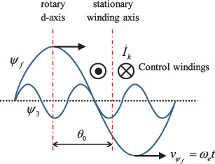
Harmonic flux interaction with injection current.
The objective of MAPT method is to optimize the amplitude of specific harmonics of the injection current, to minimize the corresponding orders of the torque ripple. Since the control winding are separated with main windings, the injection current can be sampled directly without extraction and filtering, and the closed loop control strategy can be carried out easily as well. However, the complementary torque generated by the injection current is complicated according to (15), hence the control of torque needs to be discussed in detail.
When running in eccentric status, the electromagnetic torque ripples of the motor can be derived from the speed fluctuation, which is expressed as

FFT analysis of electromagnetic torque with rotor eccentricity (a) Torque in time domain (b) FFT spectrum.

Schematic of optimal amplitude tracking process.
An iteration process is executed to find the optimal amplitude value of injection current I
k
. The amplitude of specific torque component A
n
varies with the I
k
, which follows the rule as
The optimal point P5 is located on the target curve between P2 and P3, whose amplitude of nth harmonic is minimum and the gradient is equal to zero. It is not difficult to reach the minimum point by turning injection current step by step using (18), but the convergence rate is highly dependent on the step-size factor 𝜆 and the initial amplitude variable A
n
(0), which may suffer from uncertainties in different occasions. An improved approach for accelerating the convergence is needed. This is achieved by utilizing quadratic spline curve fitting method based on three consecutive points of P1[I
k
(t), A
n
(t)], P2[I
k
(t + 1), A
n
(t + 1)] and P3[I
k
(t + 2), A
n
(t + 2)], as described by the following
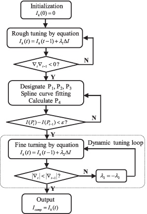
Flowchart of the MAPT method.
The scheme of FOC strategy with separated current injection method is introduced in Fig. 9. Besides the conventional FOC, the proposed algorithm employs speed fluctuation of the in-wheel motor, to calculate the torque ripples. Then, FFT is utilized to extract harmonics from the torque, and the objective harmonic is passed through the MAPT current regulator. By implementing two-stage iterations with rough and fine tuning, the MAPT is used to locate the optimum harmonic current injection commands. Finally, the compensation voltage should be added to the control winding by the independent circuit of VSI.
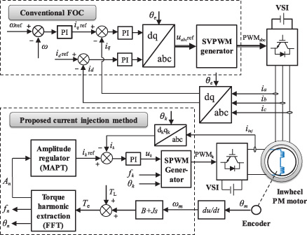
FOC scheme with proposed current injection method.
The torque harmonic compensation strategy discussed previously is simulated on the Matlab-Flux combined platform and tested in a hub motor system applied in electric motorcycles. The experimental system consists of 51-slots-46-poles in-wheel PM motors coupling with a dynamometer, a conventional three phases VSI driver and an extra single phase VSI, as shown in Fig. 10.
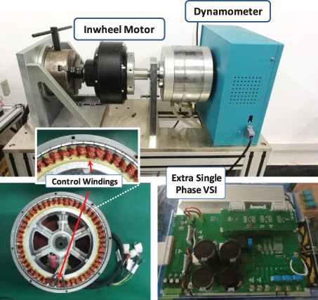
Experimental setup.
Two PM motors, one is specially designed with eccentricity and the other is original, are provided for comparison. The parameters of the specially designed in-wheel PM motor are given in Table 1. The static eccentricity is created by the deformed conical roller bearings on both sides of the end covers. As a result, the center of the inner stator offsets slightly from that of the outer rotor in vertical direction, which forms an eccentric annular gap. To execute current injection, two sets of series connected coils are mounted in the headspace of the slots at the top and bottom of both sides of the vertical axis. The terminals of the control winding are then connected to the single phase VSI.
Motor parameters
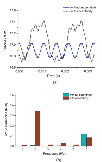
Torque harmonics considering eccentricity (a) Torque in time domain (b) FFT spectrum.
The Fig. 11(a) shows the tested harmonic torques when two motors are operating at nominal speed of 750 rpm, with and without eccentricity respectively. Figure 11(b) gives the FFT spectrum of the torque harmonics. It can be seen that the rotor eccentricity generates significantly high amplitude of second order harmonic comparing with that of other harmonics. Due to the 0.2 mm eccentric bias between inner stator and outer rotor, the 2nd-order harmonic contributes 2% on THD of torque ripples, which is approximately 50 times greater than that without eccentricity. Moreover, the Fig. 11(b) reveals other harmonics such as the fourth and sixth, therefore the injection current is deduced to have first, third and fifth components, as illustrated in (18).
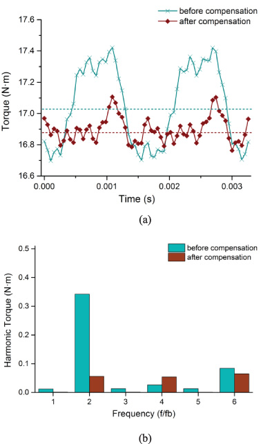
Torque harmonic compensation by current injection (a) Torque in time domain (b) FFT spectrum.
Figure 12 shows the comparison results before and after current injection. To suppress significant torque ripples, especially the 2nd-order harmonic, a current with first-order component is injected into the control winding. The amplitude and phase information of the current is A 1 = 12 A and θ1 = −2.37 rad as calculated by (18) respectively. The amplitude of the 2nd-order torque ripple is reduced to one-sixth of its original value, and the THD is reduced to 0.33% as well. In addition, according to (17) it is important to notice that, the injection current with kth harmonic component generate both k ± 1 order torques simultaneously. That means the proposed injection current of first order may cause a negative effect on dc components of torque, as shown in Fig. 12(a), the average torque is attenuated from 17.04 N ⋅ m to 16.89 N ⋅ m.
First-order current injection for 2nd order harmonic suppression.
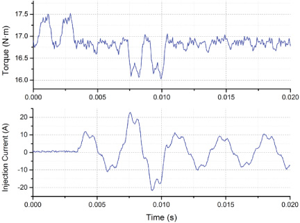
First- and fifth- order current injection for both 2nd and 6th order harmonics suppression.
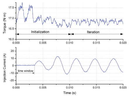
In order to verify the proposed MAPT method, the current regulation process for 2nd-order torque suppression is given in Fig. 13. Assuming that the speed does not change in a very short time, the tracking process for optimal amplitude is divided into several iteration steps in time. The iteration updates synchronously to the fundamental electrical period of the running motor. During each iteration period, the controller holds the current amplitude and samples consecutive points of the torque. When running in the rated speed at 750 rpm, the period is calculated to be 3.47 ms with 64 sampling points during the time window. It can be seen that after 3 periods of initialization, the proposed curve fitting algorithm takes another 3 consecutive periods to reach the optimal state, and then transits to fine turning stage. Besides fast convergence, the method can handle all harmonic components simultaneously by injecting multi-order currents at the same time. Figure 14 shows the suppression process for both 2nd and 6th harmonics. The injection currents containing 1st- and 5th-order components are turned simultaneously, and the iteration process finishes at the 6th period, which lasts no more than 20 ms. As shown in Fig. 15, the resulted amplitudes of 2nd and 6th harmonics are reduced by 86.3% and 56%, while the amplitude of 4th harmonic is increased due to the electromagnetic reaction of the 5th-order injection current. Since the most significant harmonics ranging from 1st to 6th orders are attenuated, the total THD is reduced from 2% to 0.51%.
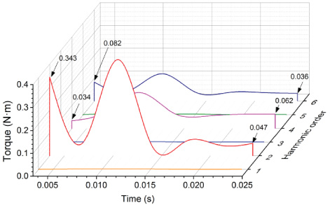
Spectrum of torque for both 2nd and 6th harmonic suppression.
When executing MAPT, an important parameter is the initial current step 𝜆ΔI, which are set to be 6 A and 10 A respectively in Figs 13 and 14. Since the quadratic curve fitting algorithm is not sensitive to initial conditions, both two current setups result in fast and stable convergence. However, the best convergence process can be obtained by setting the value of current step as
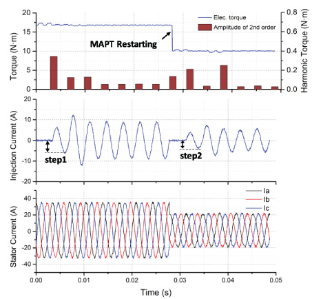
In order to test dynamic performance when the in-wheel motor is experiencing pavement potholes, a restart MAPT process after stabilization is shown in Fig. 16. As the controller adjust the propelling torque by suddenly changing the stator current from 100% to 60% of its nominal value at the restarting moment, the injection current responses quickly to the updating index of the 2nd-order harmonic. The current step marked as Step 2 is predicted to be 3.6 A based on the initial value of current step marked as Step1 according to (23), so that the torque vibration decreases during the second initialization period. It takes no more than 20 ms for the quadratic curve fitting algorithm to seek new optimal amplitude of the injection current, and the target harmonic ripple is suppressed consequently.
Dynamic response of MAPT with fast restart process.
In light EVs driven by in-wheel motors, the load mass and road impact create a tiny deformation on the motor bearings, making significant speed and torque ripples. Since the impact disturbance is dynamic, the parameters of compensation should be sought. This paper suggests a MAPT method to compensate and minimize torque ripples. The kth torque ripple can be controlled by injecting current of k ± 1 order, and the current phase is dependent on the angle of target harmonic and the position of the outer rotor. By appropriately selecting iterative size of injection current, the modified tracking process combined with quadratic curve fitting algorithm is able to suppress target harmonic ripples with fast and stable convergence. The method is less sensitive to system parameters and operation conditions, and the key iterative parameter is easier to turn than that of aforementioned literatures. The performance is evaluated by test platforms, which shows that the THD of harmonics can be reduced by more than 50%, and the turning period is shortened especially in large vibration conditions with multiple harmonic frequencies.
Footnotes
Acknowledgements
This work was supported in part by the Natural Science Foundation of Zhejiang Province under Project LQ17E070002, China, in part by the Natural Science Foundation of Zhejiang Province under Project LY17E070002, China.