
Abstract
Wireless power transfer system is playing an important role in biomedical applications by transferring power wirelessly to the implants present in the body. In this paper, magnetic coupling resonance wireless power transfer system is used to recharge battery of implantable cardioverter defibrillator. The proposed system operates at 300 KHz frequency. The LCC-C compensation topology is used to tune the coils for operating the system at stable resonant frequency and to obtain higher efficiency. In this paper, we have investigated the performance of different coil structures in multiple layer configurations and we offer recommendations on the best suitable configuration for effective transfer of power.
Keywords
Introduction
In recent days, wireless power transfer system is playing a promising role in implantable medical devices like pacemakers, cochlear implants, capsule endoscope, implantable cardioverter defibrillators, deep brain stimulators to recharge batteries without involving surgery [1–3]. The function of ICD is similar to pacemaker but with little difference. Pacemakers helps to control abnormal heart rhythms whereas ICDs monitors heart rhythms and also treats sudden cardiac arrests. An implantable cardioverter defibrillator (ICD) is a device that detects cardiac arrhythmia (irregular heart beat) and treats ventricular fibrillation. It consists of pulse generator and lead wires. Lead wires connect ICD to heart. Whenever the device observes abnormal heartbeat then it provides electric shock and brings it to normal state and to treat ventricular fibrillation it provides high energy electrical signal to the heart. The power source for the components in ICD is a battery. The batteries that power ICDs are designed with two cells in series where each cell must be capable of delivering power in excess of 3.5–5 W [4]. Each cell should be able to deliver 35 J of energy during ventricular fibrillation period. ICD is composed of pulse generator and leads (wires). Pulse generator is placed under the skin area of chest wall below the collarbone. It consists of electronic circuitry with RAM, Programmable software, a capacitor and a battery as shown in Fig. 1b.

Implantable cardioverter defibrillator (ICD).
For the defibrillation action to take place, capacitor which is present in pulse generator of ICD should be provided with high current pulses (typically 2 A for 10 s), so battery of an ICD should have high current delivering capacity and high energy density. Loss of charge of battery due internal leakages should be low. ICDs mostly use lithium/silver vanadium oxide cell or SVO battery. At the beginning of life SVO batteries will have an open circuit voltage of 3.2 V (i.e., at full charge). Battery replacement is recommended when battery voltage is less than 2.6 V.
High voltage is required to deliver high energy electrical signal in less than 10 ms during the defibrillation period. Battery present in the device cannot provide such high voltage. So, a high voltage charging circuit shown in Fig. 2 is used to step-up the battery voltage.
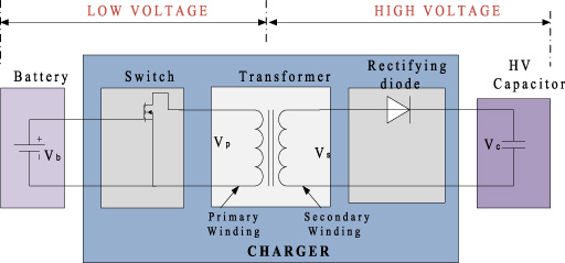
High voltage charging circuit in ICD.
High voltage charging circuit constitutes battery, charger and capacitor. Charger is composed of switch, transformer and a rectifying diode. Switch is used to convert DC voltage from battery to AC voltage by switching at high rate. This AC voltage is fed to transformer which steps up the voltage to the required value. The factor by which the amount of voltage steps up is based on ratio of number of turns in primary to that of the secondary. The high alternating voltage at the secondary is passed through the rectifying diode to convert into DC voltage. High DC voltage from rectifying diode is fed to the capacitor which store high voltage charge.
If an abnormal heart rate is detected ICD will deliver an electric shock to restore heartbeat and during ventricular fibrillation high energy electrical output (discharging of high voltage stored in HV capacitor) is applied to heart.
Major manufacturers of ICD are Medtronic, St. Jude medical, Guidant/Boston scientific, sorin group.
ICDs are playing a promising role in the life of a person suffering from cardiac diseases. Battery used in ICDs has a lifespan of 4–6 years [5]. When the battery voltage is running low device must be replaced which involves costly surgery and health hazards due to surgery. The cost involved for the device replacement and the procedure is around $37,000 [6]. If a person receives ICD with battery life of 4 years at the age of 58 then he should undergo around 5 surgeries by the age of 80.
The suitable solution to this problem is replacing non-rechargeable batteries with rechargeable batteries. In recent years, rechargeable batteries are being mostly used in biomedical implants such as deep brain stimulators, cochlear implants, pacemakers and ICDs. Rechargeable batteries can perform better than the functions of disposable batteries as they supply power for high energy consumption and current.
Advantages of WPT based ICD over conventional ICD
If rechargeable batteries are used wireless charging system is required for recharging the battery. A transcutaneous wireless charging technique should be developed for providing the power supply for the battery of ICD outside human body. For applications of biomedical systems, various means of energy transfer have been studied, such as optics, ultrasound, and biological sources, Wherein, the most established technique is wireless powering through electromagnetic induction [7]. Figure 3 represents the basic block diagram of the WPT system. Basically WPT systems are classified into inductive coupling and magnetic resonant coupling. Inductive coupling type of WPT is used for shorter distances (few mm to few cm) and magnetic coupling resonant type of WPT system provides high efficiency at mid range distances.
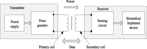
Block diagram of WPT system.
Magnetic coupling resonance WPT is also based on electromagnetic induction principle but it transfers the power at higher efficiency and at mid range distance. The system is said to be in resonant state when angular frequency of power source and the coupling resonant frequency of transmitter and receiver circuit are equal. Since at resonant state maximum amount of energy is transferred between the coils, efficiency of the system is improved.
If wireless charging system is being implemented in biomedical implant application then safety, size and efficiency should be given prior importance [8,9]. Since the receiver coil is present inside the body it should be properly designed considering the size of the implant and tissue heating.
For operating the system in resonant state different compensation topologies have been proposed and implemented to tune the two coils and thereby improving the efficiency of the system. Four basic topologies are series–series, series–parallel, parallel–series, and parallel–parallel topology. LCC and LCL topologies which are superior to series and parallel compensation have been proposed to overcome the problems present in the series or parallel compensation and also to achieve high efficiency [10]. In the proposed system LCC-C compensation is used.
In Section 2, we build the LCC-C compensation circuit model of the ICD WPT system with two coupling coils and deduce the MCR impedance matching parameters for the proposed network. The LCC-C compensation circuit refers to one inductance and two capacitors connected to the primary coil, and one capacitor connected to the secondary coil.
In Section 3, two coupling coils with different configurations (circular, square and rectangular) with different layer (single, double and triple) have been designed for charging ICD, considering the implantation of the receiver unit.
Figure 4 shows the circuit model of LCC-C compensated wireless charging system for implantable cardioverter defibrillator. In the circuit shown in Fig. 4, only a capacitor in series is used in the receiver unit to compensate the inductance of the receiving coil. So use of inductor and capacitor of LCC compensation can be avoided thereby reducing the size of the system and the current flowing through the receiving coil is relatively small [11]. Since the receiver unit consists only a capacitor and also small amount of current flowing through the receiving coil LCC-C compensation network is suitable for implantation. In Fig. 4, the inductances of the transmitting and receiving coil are labeled as L 1 and L 2 respectively. The compensation capacitances on the transmitter side are represented as C 1 and C f1 while on the receiver side compensating capacitance is C 2. The mutual inductance between two coils is M. In the following part we derive the impedance matching parameters of LCC-C compensation network for MCR-WPT system.
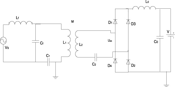
Circuit model for LCC-C compensated WPT system.
The system operates at constant resonant frequency as ω0, according to proposed LCC-C compensation network, ω0, is defined as follows:
From the above resonant matching impedances we can infer that obtaining stable resonance for the system becomes easy by the use of impedance matching method. The main reasons for stable resonance are (i) matching impendence of transmitter and receiver side dependent in circuit parameters at its own side only i.e., decoupling of matching impedances of transmitter and receiver side, (ii) matching impendence of the sides are not dependent on mutual inductance of the system i.e., when transmitter and receiver coils are misaligned system will still remain in stable resonance.
We can calculate value of L
f1 using the following equation
The values of C f1, C 1 and C 2 can be calculated using Eqs. (1) and (2).
In MCR-WPT system, transmitting and receiving coils which are magnetically coupled are the key elements in this system. In this paper, transmitting and receiving coils with different coil structures and different number of layers is designed and analyzed. Simulations of transmitting and receiving coils is performed in ANSYS electronics software and corresponding inductances of transmitting and receiving coils and coefficient of coupling between coils are measured.
The transmitting and receiving coils uses Litz wire, made of copper strands (165 strands and 42 AWG). Coils are connected with flexible ferrite film of 0.3 mm thickness. Ferrite film will help in increasing the self inductance and mutual coefficient [12].
According to the ICNIRP guidelines and IEEE standards, the operating frequency range of wireless power transmission devices for medical implanted device is assessed from 100 KHz to hundreds MHz [13]. Higher operating frequency will produce higher switching losses, tissue heating and eddy current losses. For the same power level, compared to MHz WPT, the KHz WPT will have less radiation potential effect to human body. So the operating frequency of these transmitting and receiving coils is selected as 300 KHz.
The external dimensions of transmitting and receiving coils are 58 × 48 mm and 44.5 × 30.5 mm respectively. The distance between transmitting and receiving coils is 10 mm.
Coil structures have most extensively researched for low power applications. Each coils structure have its own advantages and suitably chosen based on application [14,15]. Most popular coil strictures are circular, square, rectangular and double coils. In Table 2, circular, square and rectangular coil structures with single, double and triple layers is shown.
Transmitter and receiver coils in different coil structures
Transmitter and receiver coils in different coil structures

The power transferred and transmission can be enhanced by making more magnetic flux passing through the receiver coil since it is related with mutual inductance between the coils. In the following Table 3, we observe the vector magnetic flux density distribution through transmitting and receiving coils in different coil configurations.
Magnetic flux density distribution in transmitting and receiving coils in different coil configurations
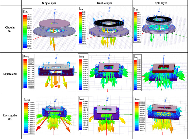
From the flux density distribution of circular, square and rectangular coil structure in different layer configurations, circular coil structure have uniform flux distribution whereas rectangular and square coil have non uniform flux density distribution. Magnetic flux density is higher in rectangular and square coils compared to circular coil, but the amount of leakage flux for circular coil structure is much less compared to rectangular and square coil configuration. Most of the leakage flux is in bottom direction. So, coupling coefficient will be greatly reduced when the coils are misaligned horizontally. Circular coils configuration have good tolerance towards horizontal misalignment because the amount on leakage flux in downward direction is less compared to square and rectangular coil structures. Higher value of flux density is obtained for single layer configuration compared to double and triple layer. Flux distribution in circular coil configuration is uniform which enables uniform power transfer since the coupling is uniform. Circular coils occupies less space compared to rectangular and square coil structures and hence material required for circular coils is less than other two coil structures. So, because of the above reasons circular coils are mostly used for effective power transfer in the system.
The coils are shielded with ferrite material to reduce the leakage flux and increase the coupling between the coils. The system is operated at a lower resonant frequency of 300 KHz considering the electromagnetic fields (EMF) safety aspects on human body, efficiency of the system and field penetration into the body.
The transmitting and receiving coil inductance values for different coil structures in different layer configurations obtained from ANSYS simulations are listed in Table 4.
Transmitting and receiving coil parameters of different coil structure in different layer configuration
A circuit model of the proposed network is built in LTspice XVII to simulate the performance of the proposed system. In the proposed system LCC-C compensation is being used. Simulation is performed for proper tuning of circuit parameters.
Transmitting and receiving coil inductances, coupling coefficients are obtained from ANSYS simulations and compensation topology parameters are calculated using (1), (2) and (3) which are tabulated in Table 5. Transmitting and receiving coils uses Litz wire made of copper strand (165 strands and 42 AWG) to decrease the resistance.
Compensation parameters values for circular, square and rectangular coils in different layer configurations
Compensation parameters values for circular, square and rectangular coils in different layer configurations
On simulating the proposed system with the parameters obtained from calculations and ANSYS simulation for the circular, square and rectangular coil configuration in different layers, the values of input and output voltages and currents and power obtained are listed in Table 6. The waveforms of input and output voltages and currents before rectifier for circular coil configuration in different layers are shown below.
Simulation results for circular coil structure:
(i) Single layer:
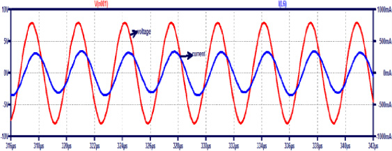
Voltage and current waveforms at input side.

Voltage and current waveforms at output side.
(ii) Double layer
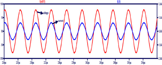
Voltage and current waveforms at input side.
Voltage and current waveforms at output side.
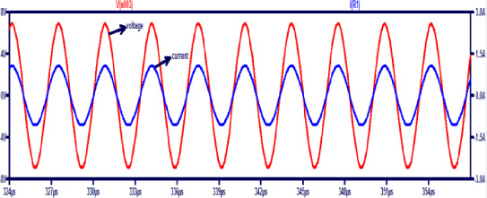
(iii) Triple layer

Voltage and current waveforms at input side.

Voltage and current waveforms at output side.
From table 5, the values of capacitor on the receiver side is higher for single layer when compared to double and triple layer for all the three coil structures (circular, square and rectangular). Since the capacitor on the receiver side should be placed inside the body its value should be lower, so double and triple layers are preferred whose receiver side capacitor value is lower than single layer. Further, triple layer structure makes the design complex and also the parameter values of double and triple layer configurations for each coil structure (circular, square and rectangular) are almost similar with slight difference. So, double layer is investigated for the application. The values of compensation parameters of rectangular and square coil configuration for double layer structure are higher than circular coil configuration which increases the size and cost. So of the different coil structures circular coil is preferred. By simulating the proposed network in LTspice with the parameter values mentioned in Table 5 for circular, square and rectangular coil structures in different layer configurations are listed in Table 6 .
Comparison of output voltages and currents of circular, square and rectangular coils in different layer configurations
From the simulation results of the proposed network, required power output for the application is met by double and triple layer configuration of circular and square coil structures. Since the power requirement is met by both double and triple layer structures of circular and square configuration double layer structure is chosen to reduce the design complexity. Circular coils are preferred over square coils because they have uniform flux distribution and lower compensation parameter value.
In this paper, we studied the performance of various coil structures (circular, square and rectangular) in different layer (single, double and triple) configurations of transmitting and receiver coils. From the simulation study of coil structures in ANSYS electronics shows that leakage flux is higher in case of rectangular and square structures than in circular coil structure. Circular coil can be conveniently used in this application as it has less leakage flux, uniform flux distribution and high tolerance to misalignment in horizontal direction. Double layer configuration is suitable to achieve required amount of voltage to charge the ICD. In Single layer, compensation parameters values have been increased which increases the size and cost. Triple layer configuration makes the design more complex. However, large number of layer in the receiver unit is not recommendable in biomedical applications.