
Abstract
In this paper, a novel decoupling control scheme combining least squares support vector machines (LSSVM) inverse models and 2-degree-of-freedom (DOF) internal model controllers (IMC) is employed in the decoupling control system of the bearingless permanent magnet synchronous motor (BPMSM). This scheme can be used to enhance the control properties of high-precision, fast-response, and strong-robustness for the BPMSM system, and effectively eliminate the nonlinear and coupling influence. It introduces LSSVM inverse models into the original BPMSM system to constitute a decoupled pseudo-linear system. In addition, the particle swarm optimization algorithm (PSO) is used to optimize parameters of the LSSVM, which improves its fitting ability and prediction accuracy. What is more, the internal model control scheme is used to design additional closed-loop controllers, thereby improving the robustness of the entire control system. Therefore, this scheme successfully combines the advantages of the LSSVM inverse models and the internal model controller. It can enhance the stability and the static as well as dynamic properties of the whole BPMSM system while independently adjusting the tracking and interference rejection performances. The effectiveness of the proposed scheme has been verified by simulation results at various operations.
Keywords
Introduction
Permanent magnet synchronous motor (PMSM) has a series of advantages such as simple structure, high reliability, small size, light weight, high power, good low-speed power generation performance, high efficiency, and low cost [1–4]. Therefore, it has been widely studied and developed in the world today [5–10]. However, with the rapid development of advanced manufacturing equipment and advanced production processes in the direction of high precision, high speed, and high efficiency, the performance requirements for high-speed and ultra-high-speed permanent magnet motor are increasing, such as high-speed precision CNC machine tools, high-pressure sealed pumps, special robots, high-speed gyroscopes, satellite flywheels, high-speed flywheel energy storage and other high-tech driven high-tech fields [11–13]. Therefore, high-speed and ultra-high-speed permanent motor and their corresponding control technologies are one of the important research directions in the field of automated process equipment, robotics and electrical transmission.
In order to effectively overcome a series of shortcomings of traditional high-speed motors such as uneven air gap, low work efficiency and short service life, the magnetic bearing technology has been developed rapidly [14,15]. It uses special iron cores and coils to generate a controllable magnetic field force by controlling the current in the coils, and then suspends the rotor in the air to achieve no mechanical contact between the rotor and stator [16–18]. It has a series of excellent characteristics such as no mechanical friction, no wear, no lubrication and sealing, long life, etc. It fundamentally changes the form of high-speed motor rotor support. Magnetic bearing-supported high-speed motors have been significantly improved in enhancing the operating performance of the drive system, avoiding friction and wear, reducing power consumption, and increasing environmental adaptability. However, since the structure of the magnetic bearing is complicated and the axial length of the rotor is increased, it is hard to improve high power density of the magnetic bearing-supported motors [19].
One of the solutions to overcome the disadvantages of magnetic bearings is the bearingless motor. It is a new type of magnetic suspension motor which combines self-suspension and rotation functions. It embeds two different pairs of pole pairs in the stator winding, so that two different magnetic pairs of rotating magnetic fields are generated in the air gap at the same time, thereby deliberately destroying the uniformity of the air gap magnetic field of traditional motors, and generating the radial force required for the rotor to self-suspend [20,21]. The BPMSM has proven to have potential applications in high-speed CNC machine tool spindles, machinery industry, energy robotics, transportation, chemicals, aerospace and other fields. Similarly, bearingless induction motors and bearingless switched reluctance motors have been widely used in practice according to their own characteristics.
The Proportional-integral-derivative (PID) control scheme has been widely applied as a traditional control scheme [22]. However, because the proportional gain (K p ), integral time constant (T i ), and differential time constant (T d ) are relatively fixed, the whole control performance and accuracy will be inevitably affected by parameter variates [23]. Therefore, for a multivariable, non-linear, strong coupling system with unavoidable interference such as BPMSM, the traditional PID control scheme is hard to achieve high-performance control.
If the nonlinear system is linearized in some way, the whole control system can be simplified greatly. Therefore, various mature control strategies can be utilized to design suitable closed-loop controllers in the simplified control system. Nowadays, the inverse system scheme can be applied skillfully in the control strategy of non-linear systems [24]. By cascading the inverse model of BPMSM with the original BPMSM system, a decoupling pseudo-linear system is formed, and finally decoupling is realized [25]. But the realization of its decoupling linearization requires the accurate mathematical model of the controlled object. As a multivariable, non-linear, strong coupling system, the parameters of the BPMSM vary significantly with the operating conditions, coupled with the presence of load disturbances and the effects of magnetic saturation, making accurate system modeling hard. Therefore, the analytical inverse system method is hard to apply in practice, and the purpose of complete decoupling control cannot be achieved by this method alone. We also require to integrate other methods with inverse system theory to enhance the performance of decoupling control [26,27].
With the rapid development of LSSVM [28–30], its application in different fields has also been expanded accordingly, including combining with the inverse system theory to build a LSSVM inverse model. LSSVM is an extension of support vector machine. It uses a different loss function than SVM. Instead of using insensitive functions as loss functions, it uses a least squares linear system as the loss function. It replaces the inequality constraint with the equality constraint while minimizing the square term of the error. It solves the system of linear equations and speeds up the training of the SVM to a certain extent, which simplifies the problem and significantly improves the operating efficiency. Least squares support vector machines have made great progress in the identification and control of nonlinear systems. The training process follows the principle of minimizing structural risk, and the structural parameters are automatically determined according to the sample parameters, which is not prone to overfitting. It transforms the learning problem of support vector machine into solving linear equations. There is no local minima problem, and it can successfully overcome the above shortcomings of neural networks. In [31], the LSSVM inverse control scheme is employed by Z. Yang et al. To achieve the decoupling control of the bearingless induction motor, and the expert PID controllers are employed for the pseudo-linear system. However, only the decoupling control between radial displacements and speed is considered, and the robustness of the system and unmodeled dynamics of the decoupling accuracy have not been considered. Therefore, on the basis of identifying the inverse model of BPMSM by the LSSVM control scheme, the internal model control scheme is used to design its closed-loop controllers. In [32], on the basis of internal model control, the filter is added to improve the robustness and tracking performance of the whole system, and achieve closed-loop control. In [33], using a filter to detune the controller can affect the tradeoff of control performance for robustness obviously.
To date, there is little paper on the control problems of BPMSM systems based on the LSSVM inverse model and the internal model control scheme. Since the BPMSM pseudo-linear system developed using the LSSVM control scheme is a complicated linear system, the uncertainties, unmodeled dynamics, and parameters changes may unavoidably influence the characteristics of tracking, decoupling, interference rejection and robustness. The traditional internal model control can get good performance for set point tracking, but it gives a slow response to the interference suppression problem. In other words, it is hard for traditional internal model control to consider both tracking and interference suppression properties. In order to realize the quick start of the motor without overshooting, and the recovery time after load disturbance is very fast, this paper uses an LSSVM inverse control scheme plus a 2-DOF internal model controller, which also reflects the advantages of independent adjustment of tracking and interference suppression performance.
This paper is composed of the following parts. In Section 2, the suspension force principle of the BPMSM is described. In Section 3, the mathematical model of the BPMSM and its inversion will be deduced. In Section 4, the LSSVM-based internal model control strategy is employed for inverse decoupling control of the BPMSM control system, and the PSO is used to optimize parameters of the LSSVM, which improves its fitting ability and prediction accuracy, and the 2-DOF internal model closed-loop controllers are designed to enhance system robustness and eliminate the unmodeled dynamics of the decoupling accuracy. In Section 5, the relevant simulation studies are carried out to verify the effectiveness of the proposed control scheme. Finally, some conclusions are summarized in Section 6.
Principle of radial suspension force generation
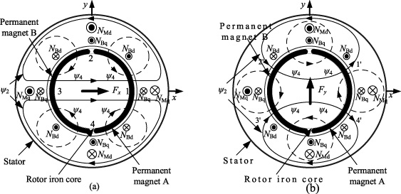
Two sets of three-phase windings are stacked in the stator slot of the BPMSM, which are a suspension force winding with a pole pair number P M of 1 and a torque winding with a pole pair number P B of 2. The radian frequency of the suspension force winding of the BPMSM is the same as that of the torque winding. When the rotor is in the center position, the symmetrical 2-pole flux is generated by the 2-pole permanent magnet. When the rotor is eccentric, the 4-pole flux 𝜓4 generated by energizing the 4-pole suspension force windings N Bd and N Bq breaks the balance of the 2-pole air gap flux 𝜓2, and finally generates radial suspension force.
The principle of the BPMSM radial suspension force generation is shown in the Fig. 1. When the motor is running at no load, the flux generated by the current in the 2-pole torque windings N Md and N Mq is small and can be ignored. When the forward current is passed in winding N Bd , the 4-pole flux 𝜓4 is generated as shown in Fig. 1(a), which will cause the flux density to increase in the airgap 1, and the flux density in the left airgap 3 reduces, so that the radial suspension force in the positive direction of the x-axis is generated, and the rotor is shifted toward the positive direction of the x-axis. If the current is passed in the opposite direction, the radial suspension force along the negative direction of the x-axis will be generated. Similarly, Fig. 1(b) is a schematic diagram of the radial suspension force generation in the y-direction. Winding N Bd and winding N Bq are perpendicular to each other in the electrical coordinate system. When a forward current is passed in winding N Bq , the generated flux 𝜓4 increases the flux density in the airgap 1 ′ and 2 ′ and makes the flux density decreases in the airgap 3 ′ and 4 ′ , and finally the radial suspension force that causes the rotor to shift toward the positive direction of the y-axis is generated. Therefore, based on the excitation flux of the motor, the magnitude and direction of the radial suspension force can be controlled by controlling the current in the 4-pole suspension force windings N Bd and N Bq , thereby achieving stable suspension of the rotor.
Principle of the radial suspension force generation.
Description of the mathematics model
When the unbalanced pull, the nonlinear magnetic saturation and iron losses are ignored, the radial suspension forces of the BPMSM in the x- and y-direction can be expressed as
In order to achieve the decoupling control between speed system and displacement system of the BPMSM, the Eq. (4) is used as the original system, and the rotational speed ω and the radial displacements x and y in x- and y-directions of the BPMSM are used as the output variables of the inverse system, then
According to the inverse decoupling control theory, the components in the output variable
Then, the Jacobi matrix can be resolved as
Hence, we can get Det(
Clearly, rank [
Through the above analysis of the reversibility of BPMSM, the inverse system of the BPMSM has been verified, but it is still hard to obtain its accurate expression formula. In addition, there are still problems such as unpredictable interference, parametric perturbations and unmodeled dynamics in practical applications, and the anti-interference and robustness of system are hard to meet. Therefore, this section will improve these problems by introducing LSSVM and internal model control scheme.
The regression principle of the LSSVM
The least squares linear system is used by LSSVM as the loss function, instead of the traditional quadratic programming method. Assume the given set of training samples
Then, the LSSVM training can be accomplished by solving the following optimization problems
The above optimization problem can be improved by the Lagrange method. The following Lagrange function can be given as
According to the KKT (Karush–Kuhn–Tuchker) optimal conditions, the solution of this optimization problem can be given as
At present, the commonly used kernel functions are linear kernel function, polynomial kernel function, Gaussian radial basis kernel function and Sigmoid kernel function. Gaussian radial basis kernel function (RBF) can obtain satisfactory results in separability and locality, so the Gaussian radial basis kernel function used in this paper can be given as
Compared with the standard SVM, LSSVM has a big problem: the sparseness of the support vector is lost. In LSSVM, all elements in the vector a are not zero, and almost all training data appears in the model as support vectors, which complicates the model and increases the amount of computation accordingly, so it should be thinned out. First of all, the absolute values of sample a k are sorted from large to small, and some of the samples corresponding to the smaller absolute value a k are removed, and the rest are trained; then the above steps are repeated. The training process of LSSVM can be reduced to a linear equation solution process, it is not necessary to solve a constrained convex quadratic programming like SVM, so that LSSVM has less computational complexity than standard SVM. The topology of LSSVM is shown in the Fig. 2.
Since BPMSM is a 3-input and 3-output system, and SVM can only be used for approximation of single-output functions, in order to realize the model identification of multiple-input and multiple-output objects, the corresponding learning machines are designed for the speed and two radial displacements.
The key to the inverse system idea is to find the inverse model of the system. According to the input data,
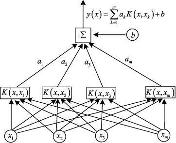
The LSSVM function fitting structure diagram.
In this part, the PSO algorithm is used to optimize the kernel width σ and regularization parameter c of LSSVM. The PSO algorithm is a type of swarm intelligence optimization technology, and it was proposed by Kennedy and Eberhart in the 20th century. Suppose a group is made up of m particles in the D dimension, and the ith dimension can be obtained as follows:
The sample mean square deviation e
RMSE can be established by Eq. (20), and the performance evaluation index of LSSVM and the objective function of the PSO algorithm can also be expressed by it, and the sample maximum absolute error e
MAXE can also be shown in (21)
Then, the steps to construct the decoupling of the inverse model of the system using LS-SVM method are as follows:
(1) Data sample collection. Sampling current signals of BPMSM as input, two degrees of freedom radial displacement and speed as output. Since the relative order of the suspension force subsystem is 2 and the relative order of the torque subsystem is 1, the five-point derivative formula is used to obtain the first derivative of the speed n and the second derivative of the displacement in the directions x and y, thus constituting the training sample set
(2) LSSVM training. According to the input and output sample data of the LSSVM, the LSSVM is trained, and the BPMSM inverse model is built. In addition, the PSO algorithm is used to optimize the kernel width σ and regularization parameter c of LSSVM. This brings the output value of LSSVM closer to the expected value. The optimized parameters of LSSVM are: c = 1800, σ = 1.9. After learning the three LSSVM, the corresponding input vector coefficients
(3) Implementation of LSSVM control. The LSSVM and integrator s −1 are used to construct the LSSVM inverse of BPMSM, and the LSSVM inverse is placed before BPMSM. The LSSVM inverse and BPMSM constitute a pseudo-linear system, which is equivalent to 3 decoupled integral linear subsystems. Among them, two second-order position integral pseudo-linear subsystems and one first-order velocity integral pseudo-linear subsystem are shown in Fig. 3.
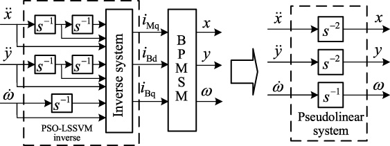
The BPMSM pseudo-linear system.
As can be seen from the above analysis, an uncomplicated open loop pseudo-linear system can be obtained by connecting the LSSVM inverse system with the original BPMSM system in series. Then, in order to achieve the high-performance control of the entire BPMSM system, the choice of high-performance closed-loop controller becomes a key part.
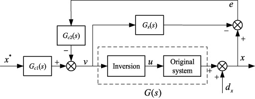
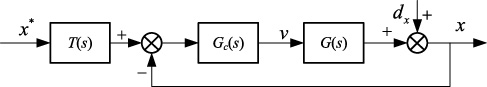
In this part, we will add the 2-DOF internal model controllers to the open-loop pseudo-linear system designed above. As can be seen from Fig. 3, the displacement control in the x and y directions and speed control have achieved decoupling control. Therefore, the controllers of these three pseudo-linear subsystems exist independently. Take the displacement control in the x direction as an example. The structure of the 2-DOF internal model controller is shown in the Fig. 4. In this structure, the real plant to be controlled is denoted by G(s), the internal model is denoted by G
x
(s), the whole internal model controllers are denoted by G
c1(s) and G
c2(s), respectively, the reference input of radial displacement in the x direction is denoted by
The 2-DOF internal model controller structure.
According to theory, the ideal transfer function of the pseudo-linear subsystem of the x-axis radial displacement can be given as
The transfer function (22) is employed to represent the nominal model of the x-axis radial displacement of the BPMSM control system. However, due to the presence of unpredictable errors and the incalculable disturbances, the composition of the actual control plant and its inverse system (16) are not equivalent to the linear subsystem completely. The transfer function of the whole pseudo-linear subsystem includes its uncertainty and noise in practice, which can be given by (23)
From Fig. 4, we can figure the output as
If the internal model is correct, that is, G
x
(s) = G(s), (24) can be expressed in a simpler form as
It can be seen from formula (25) that the tracking performance is determined only by G
c1(s), and the interference rejection property is determined only by G
c2(s). On the premise that there is no steady-state error and the robustness of the system can be improved, in order to track the reference input x, the internal model controller G
c1(s) and G
c2(s) consisting of a low-pass filter can be given as
In addition, Fig. 4 can be further simplified to Fig. 5, and the improved 2-DOF internal model controller can be designed as
The closed-loop system of the 2-DOF internal model controller.
In the same way, the 2-DOF internal model controllers for the rotor speed control system can also be obtained. In addition, the ideal transfer function of the pseudo-linear subsystem for rotor speed can be expressed as
Therefore, the 2-DOF internal model controllers of the rotor speed system can be expressed similarly as
As shown in Fig. 5, the output error transfer function of the closed-loop system can be defined as
In order to further analyze the property of the tracking, we assume the internal model is right and let d
x
(s) = 0 and G(s) = G
x
(s), and E
1(s) can be expressed in formula (31). In the same way, in order to analyze the interference rejection performance, we let x
∗(s) = 0 and G(s) = G
x
(s), and E
2(s) can be expressed as
It can be seen from (31) that as 𝜆2 is smaller, the interference rejection performance is better, and as 𝜆1 is smaller, the tracking performance is better.
In addition, when analyzing the tracking property, adding the step and sinusoidal signals respectively, the stability error of the whole closed-loop control system can be expressed by (32). When analyzing the disturbance rejection property, adding the step and sinusoidal signals respectively, the stability error of the entire closed-loop control system can be expressed by (33).
It is obvious that the step and sinusoidal signals can be tracked by the closed-loop control system without steady-state errors and step and sinusoidal interference signals can also be rejected.
For arbitrary ω, the sufficient and necessary condition for stabilization of the closed-loop system can be shown as
From (35), it can be drawn a conclusion that considering a certain modeling error upper bound
By clarifying the system performance indexes and robust stability above, we can select the optimal control parameter sets 𝜆1 and 𝜆2 to enable effective independent control of tracking and robust performance. The entire control block diagram of the proposed 2-DOF internal model control based on LSSVM inverse control scheme for the BPMSM system is shown in Fig. 6.
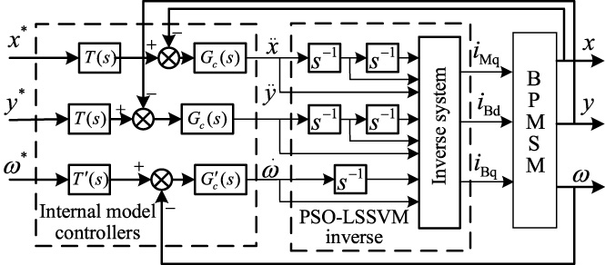
Control block diagram of the entire system.
In order to further validate the effectiveness of the proposed strategy, the simulation between the proposed control system and the inverse system method plus PID controller have been carried out. The system parameters and the parameters of the two control schemes are shown in Tables 1–3.
Parameters of the prototype machine
Parameters of the prototype machine
Parameters of the 2-DOF internal model controller
Parameters of the PID controller
The simulation parameters of PSO are shown below: m = 60, D = 2, c 1 = c 2 = 2, the number of termination iterations is k = 250, and the attenuation of 𝜛 is from 0.84 to 0.46. In this paper, the prediction root mean squar error (ϵRMSE) and the maximum absolute error (ϵMAXE) are employed to be as definition of evaluation indicators which evaluate the prediction performance of the LSSVM model. The maximum absolute error (ϵMAXE) is defined in (21) and the prediction root mean squar error (ϵRMSE) is defined in (20). In order to verify the effectiveness of the PSO algorithm, the inverse model of BPMSM is established by employing the classic SVM and PSO-LSSVM, respectively. According to the test data selected from 400 groups, the ϵRMSE and the ϵMAXE were made the comparison respectively, and the results are shown in Table 4. It can be seen that the PBMSM inverse model based on PSO-LSSVM has better fitting ability and prediction accuracy.
Comparison of the two kinds of model prediction effect
Comparison of the two kinds of model prediction effect
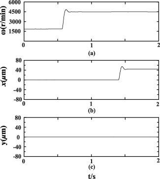
According to the simulation of speed step and displacement step in BPMSM system, the decoupling characteristics of the whole proposed control system are verified. At t = 0.6 s, the reference velocity increases from 2000 r/min to 4500 r/min, and at t = 1.4 s, the x-axis reference radial displacement rises from 0 to 45 μm. the simulation result is shown in Fig. 7. The Fig. 7 is arranged from top to bottom according to the speed and the radial displacement of the rotor in the x and y directions, respectively.

Decoupling properties of the inverse system method plus PID controller: (a) rotor speed (b) x-axis rotor displacement (c) y-axis rotor displacement.
Decoupling properties of the proposed control scheme: (a) rotor speed (b) x-axis rotor displacement (c) y-axis rotor displacement.
It can be seen from Fig. 7 that at t = 0.6 s, the speed reference suddenly rises from 2000 r/min to 4500 r/min. For the inverse system plus PID controller scheme, the x-axis and y-axis radial displacement overshoots are approximately 14 μm and 15 μm, respectively. And the response of speed has an overshoot of approximately 500 r/min. However, compared with the inverse system plus PID controller scheme, it can be seen from Fig. 8 that at t = 0.6 s, when the speed reference value suddenly rises from 2000/min to 4500 r/min, the proposed control scheme has almost no fluctuations of the x-axis and y-axis radial suspension system. This proves that not only does the suspension system of the BPMSM have a strong coupling in the x-axis and y-axis radial displacements, but also a strong coupling between the two radial suspension control systems and a speed control system. In contrast, compared with the inverse system plus PID controller scheme, when the x-axis reference displacement of the BPMSM increases from 0 to 45 μm at t = 1.4 s, the proposed control scheme hardly affects the radial suspension system in y-direction, and the interference to the rotor speed system is very small. Then we can find that the sudden variation of one reference input has little effect on the other two outputs. This shows that by applying the proposed control scheme, the decoupling control between the two radial suspension and the rotor speed control system of the BPMSM can be achieved, and the response speed and control accuracy are greatly improved.
In this section, according to the simulation of speed step, external interference and parameter change in BPMSM system, the interference rejection, tracking and robustness performance of the proposed control scheme are verified. The reference speed increases from 0 r/min to 5500 r/min at t = 0 s. After about 0.8 s, the magnetically suspended rotor is subjected to a radial interference of 3 N ⋅ m. At t = 1.6 s, the Maxwell force constant K M is reduced by 20%. In addition, in order to further distinguish the properties of the two control schemes, various control parameters have also been applied, as shown in Figs 9 and 10, and the control parameter k d of the inverse system method plus the PID controller in Fig. 9 is 0.5 and the control parameters 𝜆1 and 𝜆2 of the proposed control method in Fig. 10 are 0.061 and 0.039, respectively.
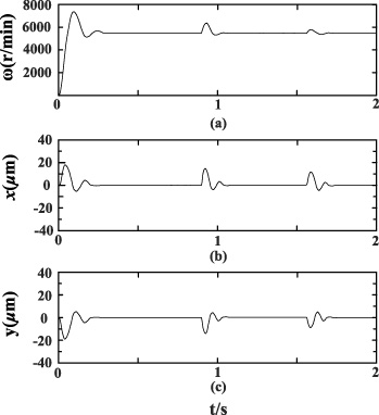
Tracking and interference rejection properties of the inverse system method plus PID controller: (a) rotor speed (b) x-axis rotor displacement (c) y-axis rotor displacement.
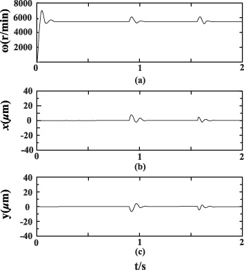
Tracking and interference rejection properties of the proposed control scheme: (a) rotor speed (b) x-axis rotor displacement (c) y-axis rotor displacement.
In order to further study the interference rejection, tracking and robustness performance, this paper determines the definition of some important performance indicators, and analyzes how these performance indicators change as the control parameters of the system vary. In respect to the speed step of the rotor system of the BPMSM, we set the setting time and overshoot as the two main indexes. With regard to the interference rejection and robustness performance, we set the setting time and deviation value as the key indexes. It is worth striking here that the deviation value is expressed as the maximum deviating value from the steady-state position if external interference or parameter changes happen.
As shown in Fig. 9, regarding to the inverse system plus PID controller scheme, when the reference speed increases from 0 r/min to 5500 r/min at t = 0 s, the reference speed input has the fluctuations of about 1900 r/min (i.e., the overshoot is 35%), and the setting time is 0.15 s. Moreover, at t = 0.8 s, when a 3 N ⋅ m radial interference is applied to the magnetically suspended rotor, the setting times and deviation values of radial displacements are respectively 0.11 s and 17 μm, the setting times and deviation value of the speed are 0.12 s and 700 r/min, respectively. At t = 1.6 s, when the Maxwell force constant K M suddenly varies, the setting time and deviation values of the speed are 0.11 s and 650 r/min, and the setting times and deviation values of radial displacements are respectively 0.12 s and 16 μm. On the contrary, from Fig. 10, it can be seen that with respect to the proposed control strategy, the speed tracking curves are relatively stable, with slight overshoot, and the setting times are short when the reference speed step, external interference and parameter vary. This also greatly suggests that the proposed scheme is superior to the inverse system method plus PID controller in terms of tracking, interference rejection and robustness properties.
In addition, taking the rotor speed control system of the BPMSM as an example, by varying the parameter of the scheme, the more accurate contrast is shown between the two schemes. When the control parameter k d of the inverse system method plus the PID controller and the control parameters 𝜆1 and 𝜆2 of the proposed control method change, the aforementioned property indicators will vary, and the relevant parameters are shown in Table 5.
In addition, as shown in Table 5, taking the rotor speed control system of the BPMSM as an example, a more detailed comparison is made between the proposed scheme and the inverse system plus PID controller scheme. When the control parameter k d of the inverse system method plus the PID controller and the control parameters 𝜆1 and 𝜆2 of the proposed control method change, the above-mentioned performance indicators will vary, and the parameters are shown in Table 5.
Comparative results between two control schemes with parameters varying
For the inverse system plus PID controller scheme, it can be clearly seen from Table 5 that the control parameter k d rises from 0.5 to 0.8, the settling time of the speed response will increase regardless of the presence of external interference or parameter variations. On the contrary, the overshoots of the speed response are reduced.
Therefore, with respect to the inverse system plus PID controller scheme, the conclusion can be obtained that the properties of tracking and interference rejection cannot be adjusted independently. Thus, because there are always modeling errors, when the operating points of the system vary, it is hard for the inverse system plus PID controller scheme to get the optimal control coefficient. In other words, even if the optimal control coefficient of the inverse system method plus PID controller can sometimes be set, the tracking and interference rejection performance cannot be satisfied at the same time.
Nevertheless, with respect to the proposed control scheme, decreasing the values of 𝜆1 and 𝜆2 can reduce both the overshoots of the speed response and the setting times. Specifically, by reducing the control parameters 𝜆2, the interference rejection and robustness can be enhanced without any effect on the tracking performance. From another perspective, by reducing the control parameters 𝜆1, we can improve the property of tracking without any impact on interference rejection and robustness properties. Thus, we can get a conclusion that the tracking and interference rejection performance can be adjusted by the proposed control scheme independently. This is consistent with the analysis in Section 4.3. The same conclusion can be reached for the x- and y-axis radial displacements Similarly.
According to the above-mentioned simulation results, compared with the inverse system plus PID controller scheme, it is obvious that the proposed LSSVM control scheme plus internal model controller has great enhancements in many aspects such as high accuracy, fast response and high robustness. The stability and static of the control system have been improved, and the dynamic properties of the entire BPMSM system have also been enhanced.
In view of the multivariable, strong coupling, and non-linear characteristics of the BPMSM control system, this paper puts forward a decoupling control scheme combining the LSSVM control method and the 2-DOF internal model controllers. It can be used to improve the control performance of the BPMSM system, including improving accuracy, achieving fast response and strong robustness, and effectively eliminating the nonlinearity and coupling effects of the BPMSM control system. From the simulation results of the control system of the BPMSM, we can draw the following conclusions: (1) The LSSVM inverse control scheme can effectively implement decoupling control of the BPMSM system; (2) By using the LSSVM inverse control system plus 2-DOF internal model controllers scheme, the unmodeled dynamics to the decoupling precision can be removed successfully; (3) After employing the PSO algorithm, the inverse model can be better identified by LSSVM, and the higher fitting and precision can be obtained; (4) By adjusting the control parameters 𝜆1 and 𝜆2, the tracking and interference rejection characteristics can be independently adjusted.
Footnotes
Acknowledgment
This work was supported by the National Natural Science Foundation of China under Projects 52002155 and 51875261, and the Natural Science Foundation of Jiangsu Province of China under Project BK20180046.