
Abstract
A novel squirrel cage eddy current coupling with adjustable radial air gap was presented, which can change the output speed by changing the air gap thickness in radial direction between the copper strips and the permanent magnet. It has the advantages of no axial force in speed regulation and less eccentric force in axisymmetric structure. The 2-D electromagnetic torque model of the rotor was established, and the influence of the air gap thickness on the electromagnetic torque was also studied by finite element method. Further, a novel method to solve the dynamic equation of the eddy current coupling was proposed based on the effect of air gap thickness and relative speed on torque characteristics, and was applied to the speed regulation performance analysis. In addition, the influence of the relative magnetic permeability of the permanent magnet back yoke and the internal rotor on the speed regulation performance was studied.
Keywords
Introduction
The eddy current coupling is a non-contact transmission device with the advantages of static sealing, soft start, smooth operation, overload protection and less maintenance [1,2], and has the function of speed adjustment. Compared with variable frequency speed regulation and hydraulic speed regulation, the speed regulation of eddy current coupling has the advantages of simple structure and no harmonic pollution to the power grid [3]. Therefore, the eddy current coupling with adjustable speed plays an important role in the many fields, such as hydraulic pump, draught fan, vacuum transmission, wind power generation, vehicle auxiliary power generation and the like [4–6]. The permanent magnet eddy current coupling can be divided into an axial type and a radial type according to the rotor structure [7–9]. The axial eddy current couplings have the advantages of simple structure, low requirements for central symmetry and its speed can be adjusted by changing the air gap thickness through axial movement. However, they have axial forces and are not suitable for heavy loads. The radial eddy current coupling has the advantages of compact structure and speed regulation by changing the coupling area of internal and external rotors through axial movement, which has a wide application prospect. It has been an important direction to improve the structure of eddy current coupling.
In 2006, Razavi et al. proposed an axial eddy current coupling with a slotted rotor, and in subsequent studies used a slotted structure in the eddy coupling rotor to reduce stray eddies on the copper and increase the output torque [10]. On this basis, in 2016, Liang et al. proposed a radial eddy current coupling with slotted structure, called as squirrel cage eddy current coupling. Compared with the torque density of the typical radial eddy current coupling, its torque density has been significantly improved and has a good application prospect [11].
At present, the speed regulation method of squirrel cage eddy current coupling is the same as that of radial eddy current coupling, the speed regulation is realized by moving the internal rotor along the axial direction [12] to change the coupling area between copper and permanent magnet. Yang et al. studied the axial force produced by moving the rotor along the axial direction for the speed regulation [13]. This axial force affects the stability of the eddy coupling during operation and the accuracy of the speed adjustment. In addition, Li designed a radial eddy current coupling based on the mechanical flux adjustment method [14,15], in which an axially movable stator ring (MSR) is used to change the air gap magnetic flux. Due to the change of air gap flux, the eddy current coupling can adjust the speed. The rotor of the eddy current coupling designed by Li no longer moves along the axial direction, but needs a MSR. In this case, both the radial dimension of the eddy current coupling and the dynamic inertia moment become larger, which would affect the stability of torque transmission. Therefore, it is an important research direction to design a squirrel cage eddy current coupling without axial force and with compact structure.
There are two main methods for studying the performance of eddy current couplings, analytical methods and numerical methods [16]. The former is to analyze the performance of the eddy current coupling by theoretical analysis and establishing the mathematical model of the eddy current coupling. The typical methods are the separation variable method [16,17], the linear layer theory method [4], the equivalent magnetic circuit method [18–20], etc. Wang proposed a simple and practical performance calculation method of permanent magnet eddy current coupling based on equivalent magnetic circuit (MEC) model, which provides a relatively simple calculation method for the performance analysis of eddy current coupling [21]. In the numerical methods, the finite element analysis (FEA) method is used to study the static/transient magnetic field [22–25], output torque [26], axial force [13] and temperature field [27], etc. In 2016, Julien solved the eddy current problem by using two classical formulas based on magnetic vector and scalar potential, and calculated the electromagnetic torque of the axial type eddy current coupling using the three-dimensional finite element analysis model. The results were compared with the experimental results of the designed magnetic drive device, which showed that the numerical calculation results are in good agreement with the experimental results [28]. In the FEA, it is assumed that one of the internal rotor and external rotor does not move, and the relative speed is given to another one. Then the research on the effect of eddy current coupling structural parameters and relative speed on the air gap magnetic field and the output torque is carried out. The structural parameters include the number of permanent magnets, permanent magnet thickness, etc. Usually, the analytical method is applicable to the eddy current coupling with relatively simple structure, and FEA method for one with complex structure.
In the current research, there is little research on the speed characteristics. In 2013, Mirsalim et al. analyzed the transient speed of eddy current coupling [29]. They did not change the speed of the prime mover, and changed the external load of the outer rotor to study the relationship between the output speed and time. At the same time, they also did not change the external load of the rotor, and changed the output speed of the prime mover to study the relationship between the output torque and time. The article analyzed the speed characteristics of the eddy current coupling, but it did not study the speed regulation performance of the eddy current coupling, especially the influence of the regulation parameters and structural parameters on the speed regulation performance. From the current research situation, in the performance analysis of the eddy current coupling, it is mainly to study the electromagnetic field and output torque, and less to research on the speed regulation performance of the eddy current coupling. Therefore, the research on the speed regulation performance of the eddy current coupling would provide an important reference for the design of the eddy current coupling.
In view of the problem of large axial force and size caused by the speed regulation of the squirrel cage eddy current coupling (radial type) by axially moving the rotor, this paper proposes a novel squirrel cage eddy current coupling with adjustable radial air gap, which can adjust the output speed by changing the air gap thickness between copper and permanent magnet. The novel eddy current coupling has the characteristics of compact structure, small radial size, no axial force and low eccentric force. At the same time, the COMSOL FEA software is used to analyze the air gap magnetic field, electromagnetic torque and eddy current of the eddy current coupling, and the influence of the air gap thickness on its electromagnetic torque is studied. In order to study the speed regulation performance of the eddy coupling, this paper also presents a method to solve the dynamic equation of the eddy current coupling based on the effect of air gap thickness and relative speed on torque characteristics, and studies the influence of the relative magnetic permeability on the regulation performance.
The structure and principle of squirrel cage eddy current coupling with adjustable radial air gap
Structure and principle of typical squirrel cage eddy current coupling
The typical structure of the squirrel cage eddy coupling consists mainly of internal rotor and external rotor, as shown in Fig. 1. The external rotor is inlaid with radially magnetized permanent magnet, and the magnetization directions between adjacent permanent magnets are opposite. The internal rotor is made of a metal material with good magnetic permeability. And a rectangular groove in the axial direction is also designed on the internal rotor, and a copper strip with good electrical conductivity is installed in the groove. Conductive rings are respectively arranged at both ends of the internal rotor for connecting the respective copper strips. Since there is no direct contact between the adjacent copper strips, the stray eddy current generated in the copper strip is limited. During operation, the motor drives the internal rotor of the squirrel cage eddy coupling to rotate. Under the action of the magnetic field, the induced eddy current is generated in the copper strip of the internal rotor, and the external rotor is subjected to the electromagnetic torque under the action of the induced magnetic field, thereby realizing the transmission of the torque. A typical speed adjustment method for a squirrel-cage eddy coupling is shown in Fig. 2. For changing the output speed of the squirrel cage eddy coupling, the internal rotor (or external rotor) moves in the axial direction, and the coupling area of the copper strips and the permanent magnet changes after the movement. In order to balance the external load, the relative rotational speed between the internal rotor and the external rotor is changed, thereby realizing the speed control function. Although the method of adjusting the speed by moving the rotor is simple, the internal and external rotors are deviated from the equilibrium position after the speed adjustment, thereby an axial force is generated. At the same time, the speed regulating device of squirrel cage eddy current coupling is usually arranged on one side of the outer surface of the internal rotor, which brings about the problem of eccentric force on the one hand and increases the radial size of the coupling on the other hand, which is not conducive to the stable transmission of torque.

Schematic diagram of squirrel cage eddy current coupling.

Speed regulation process of typical squirrel-cage eddy current coupling. (a) Before speed adjustment. (b) After speed adjustment.
In order to overcome the disadvantages of the typical squirrel cage type eddy current coupling, such as the axial force caused by the speed regulation, the eccentric force caused by the arrangement of the speed regulating device and the large radial size, this paper proposes a novel squirrel cage type eddy current coupling with adjustable radial air gap, as shown in Fig. 3. It is composed of internal rotor, external rotor and speed regulating device. Based on the typical squirrel cage eddy current coupling, the internal rotor and speed regulating device are improved. On the one hand, the depth of the rectangular groove of the internal rotor is increased, which provides the space for the copper strip to move along the radial direction, on the other hand, the end face of the eddy current coupling is equipped with a speed regulating device, which can drive the copper strip to move along the radial direction, and realize the speed regulation. Figure 3(b) is the speed regulating device of squirrel cage eddy current coupling with adjustable radial air gap which is mainly composed of speed regulating motor, screw disc and push rod. The screw disc and push rod are coupled by plane thread with equal pitch designed on them, and has the function similar to the three jaw chuck of machine tools. During speed regulation, the motor drives the screw disc to rotate, and then the push rod moves along the radial direction under the action of the thread, and changes the air gap thickness between the copper strips and the permanent magnet (as shown in Fig. 4). The change in the thickness of the air gap causes the balance of the torque transmission of the coupling to be broken, the relative rotational speed between the two rotors changes in order to reach a new balance. Although the axial size of the squirrel cage type eddy current coupling with adjustable radial air gap increases a little due to the existence of the speed regulating device, the axial force will not appear during and after the speed regulation. In addition, due to the better axisymmetric characteristics of the speed regulating device, the eccentric force of the coupling is relatively low. Therefore, the squirrel cage eddy current coupling with adjustable radial air gap can be applied widely.
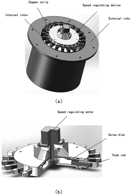
Structure of squirrel-cage eddy current coupling with adjustable radial air gap. (a) The overall structure of the coupling. (b) The structure of the speed regulating device.

Speed regulation process of squirrel-cage eddy coupling with adjustable radial air gap.
Method of electromagnetic torque analysis
2-D FEA method is used to analyze the electromagnetic torque of squirrel cage eddy current coupling with adjustable radial air gap, and the 2D geometric model is shown in Fig. 5. The specific dimensional parameters of the eddy current coupling are defined as follows: R 0 is the inner radius of external rotor, H m is the thickness of permanent magnet, R I is the outer radius of internal rotor, h is the thickness of air gap, L is the length of coupling, W copper is the width of copper, H copper is the thickness of copper, n P is the number of magnet and n copper is the number of copper strips.
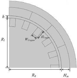
2D FEA model of squirrel-cage eddy coupling.
In addition, the following assumptions are made in the 2D FEA: The magnetization direction of the permanent magnet is radial and evenly distributed, and the residual magnetic flux density of the permanent magnet is B
r
= 1.21 T. The internal rotor material needs only to consider the magnetic saturation state, and the relative magnetic permeability of the internal rotor is expressed by the B-H curve, and the relative magnetic permeability of the other materials is constant. The end effect of the squirrel-cage eddy coupling is ignored, while the axial flux on the eddy coupling is ignored. Only copper strips are conductive in the internal rotor. The external rotor does not move, the internal rotor rotates, and the given rotational speed is the relative rotational speed. On analyzing the electromagnetic torque, the air gap thickness in radial direction between the copper strips and the permanent magnet is given in advance and kept unchanged.
The theoretical basis for the FEA of the squirrel-cage eddy coupling is Maxwell’s equations, as mentioned in [20] and [26]. By combining the Maxwell’s equations and assumption (1)–(6), the governing equations are deduced for the copper strip area, the permanent magnet area and other area of the squirrel cage eddy current coupling with adjustable radial air gap proposed in the paper, which are as follows: Copper strip area Permanent magnet area Other area
where μ is the relative magnetic permeability, A is the vector magnetic potential, v is the relative rotational speed of internal rotor and the external rotor, σ is the electrical conductivity of the copper strip, B r is the residual magnetic flux density of the permanent magnet material.
For the calculation of electromagnetic torque, the components of magnetic and rotating machinery of COMSOL Multipysics FEA software and Maxwell stress tensor are used to obtain the electromagnetic torque with time.
The time stepping used in FEA is determined by the backward difference formula. The initial time stepping is 0.001 s, and the maximum time stepping is 0.1 s, which are the default time stepping of COMSOL Multiphysics FEA software. Since the eddy current coupling has no induced magnetic field at the beginning, its initial magnetic field is only generated by permanent magnet, that is, B = B PM (B PM is the magnetic field generated by permanent magnet, especially for permanent magnet area, B = B r ). As an example, the structural parameters and electromagnetic parameters used in the analysis are shown in Table 1.
The structural parameters and electromagnetic parameters data sheet
Method of the speed regulation performance analysis
At present, the performance analysis of the eddy current coupling is mainly based on the assumption that the relative speed of the internal rotor and the external rotor is constant, and then the FEA software is used for calculation. This method can obtain the output torque of the eddy current coupling when it is running stably, and the calculation amount is relatively small because the relative speed is assumed to be constant. However, this method does not take into account the load conditions and the effect of speed on torque during operation. At the same time, because the relative speed is constant, the output speed characteristics cannot be reflected. So this method cannot to be used to analyze the speed regulation performance of the eddy coupling.
In order to obtain the change of the output speed of the eddy current coupling with time in speed regulation, a direct method is to use the FEA software combined with the dynamic equation for simulation analysis. Since the FEA software is repeatedly called to obtain the torque corresponding to the relative speed and air gap thickness on solving the dynamic equation, this method takes a large amount of calculation on-line. In 2014, when El-Wakeel et al. optimized the PM coupling, they used the effect of air gap thickness and relative speed on torque as the constraint of the optimal design [30]. Under the influence of this idea, a method of speed regulation performance analysis is proposed. First the curved surface of the effect of air gap thickness and relative speed on torque characteristics is obtained by using the FEA software in electromagnetic torque analysis as mentioned in Section 3.1. Then the curve surface is used to solve the torque dynamics equation of the eddy current coupling. This method has the advantage of less calculation on-line due to only interpolation calculation needed based on the curved surface, so as to quickly obtain the speed regulation performance of the eddy current coupling. At the same time, in this method there is an assumption that the air gap thickness changes during the speed regulation in very short period of time, so that the time of the change of the air gap thickness can be ignored. The detail solution process of this method is as follows.
First of all, the FEA software is to obtain the curved surface of the effect of air gap thickness and relative speed on torque characteristics, as shown in Fig. 6. The air gap thickness of the squirrel cage eddy coupling changes from 2 mm–10 mm and the relative speed from 20 RPM to 1490 RPM. For any air gap thickness and relative speed, the torque can be easily obtained by the interpolation calculation based on the curved surface.

The effect of air gap thickness and relative speed on torque characteristics.
Then, Newton’s second law is used to establish the torque dynamic equation, as follows:
Finally, since the differential equation ((4)) is a typical first-order differential equation, the Euler method can be used to solve by
On solving, the curved surface of the effect of air gap thickness and relative speed on torque characteristics are applied, and the change of the output speed of the eddy current coupling with time is obtained.
In order to measure the speed regulation performance of the eddy current coupling, the speed regulation range Δv, the speed regulation time t
v
and the static rate S are used and described by
In the formula (7)–(9), v s is the speed when the eddy current coupling is in stable operation before the change of air gap thickness, v E is the speed when the eddy current coupling reaches stable operation after the change of air gap thickness, t s is the starting time when the air gap thickness changes, t E is the time when the eddy current coupling reaches stable operation after the change of air gap thickness, Δv N is the speed difference when the load of the eddy current coupling increases from the ideal no-load to the rated load, and v 0 is the speed when the load of eddy current coupling is ideal no-load. The speed regulation range and speed regulation time are used to measure the performance of the eddy current coupling during the speed regulation process, and the static rate is used to measure the stability of the speed regulation of the eddy current coupling.
In the analysis of speed regulation, it is assumed that the load of eddy current coupling is constant torque load, and its value is TF = 500 N ⋅ m for the following case study.
Electromagnetic torque analysis results
The method described in the previous Section 3.1 are used. The magnetic flux density distribution of eddy current coupling obtained is shown in Fig. 7. For the external rotor of the eddy current coupling, the magnetic field is mainly distributed in the joint of adjacent permanent magnets, which also leads to the larger flux density when the teeth of the internal rotor pass through the joint of the adjacent permanent magnets. The more calculation results are as follows.
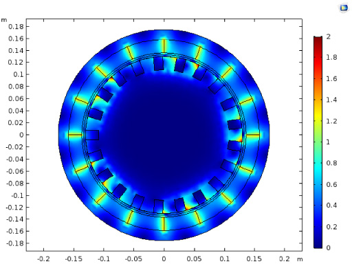
The magnetic flux density distribution of eddy current coupling.
The magnetic flux density close to the permanent magnet side and the magnetic flux density close to the internal rotor side are obtained. The former can be considered as the magnetic flux of the permanent magnet output, and the latter can be considered as the effective magnetic flux acting on the copper strip. As shown in Fig. 8, with the increase of time, the air gap flux density first decreases and then increases, and finally gradually stabilizes at a certain value (or fluctuate around a certain value). This is because with the start of the eddy current coupling, the eddy current of the copper strip increases gradually, which makes the induced magnetic field of the copper strip increase gradually. According to Lenz’s law, the induced magnetic field has an obstructive effect on the original magnetic field, so the air gap flux density would gradually decrease after the start of the eddy current coupling. When the copper eddy gradually stabilizes, the induced magnetic field hardly changes, and the eddy current coupling air gap magnetic flux density stabilizes at a certain value (or fluctuates around a certain value). As shown in the Fig. 8(a) and Fig. 8(b), the stable magnetic flux density on the permanent magnet side and the internal rotor side is 0.61 T and 0.48 T respectively. The magnetic flux density on the permanent magnet side is larger than the magnetic flux density on the internal rotor side, which is caused by the magnetic leakage in the air gap. At the same time, it can be noted that the fluctuation of the magnetic flux density on the internal rotor side is much larger than that on the permanent magnet side, which is related to the induced magnetic field generated by the eddy current of the copper strip.

The magnetic flux density of the air gap varies with time. (a) The magnetic flux density on the magnet side. (b) The magnetic flux density on the internal rotor side.
The eddy current density of a single copper strip with time is shown Fig. 9(a). The eddy current density of a single copper strip changes periodically with time. This is caused by the copper strip cutting the magnetic induction line in the circumferential periodic magnetic field generated by the permanent magnet. The average eddy current density of all copper strips is shown in Fig. 9(b). After the eddy current coupling is started, the eddy current density of the copper strips does not reach a stable value immediately. There is a process in which the eddy current density increasesfirst, then decreases, and finally stabilizes near at 1.3 × 10⁷ A/m2. This change makes the induced magnetic field have the same change rule, which is consistent with the analysis of the change in magnetic flux density of Fig. 8. As shown in Fig. 9(c), with the increase of time, the output torque of the eddy current coupling increases first, then decreases, and finally stabilizes near at 1050 N ⋅ m, The change of torque with time is the result of the interaction of eddy current and magnetic flux density.

The eddy current density and output torque with time. (a) The eddy current density of a single copper strip. (b) The average eddy current density of all copper strips. (c) Output torque.
The squirrel cage eddy current coupling designed in this paper has the function of adjusting the output speed by changing the air gap thickness, so the size of the air gap thickness has an important impact on the output performance of the eddy current coupling. The influence of air gap thickness on the electromagnetic field and torque of eddy current coupling is discussed as follows.
The influence of air gap thickness on coupling performance is shown in Fig. 10, the output torque in Fig. 10(a), the eddy current density of copper strip in Fig. 10(b), the magnetic flux density on the magnet side in Fig. 10(c), and the magnetic flux density on the internal rotor side in Fig. 10(d). With the increase of air gap thickness, the output torque, the eddy density of copper strip,the magnetic flux density on the magnet side and the magnetic flux density on the internal rotor side of the eddy current coupling decrease gradually. This is because with the increase of the air gap thickness, the magnetic leakage of the permanent magnet in the air gap increases, which makes the air gap flux density decrease, and further reduces the output torque. As shown in Fig. 10(a), when the air gap thickness changes from 2 mm to 10 mm, the output torque of the eddy current coupling is reduced from 1668 N ⋅ m to 665 N ⋅ m, and the torque change rate is as high as 60.1%, which shows that the eddy current coupling has a large torque regulation range.
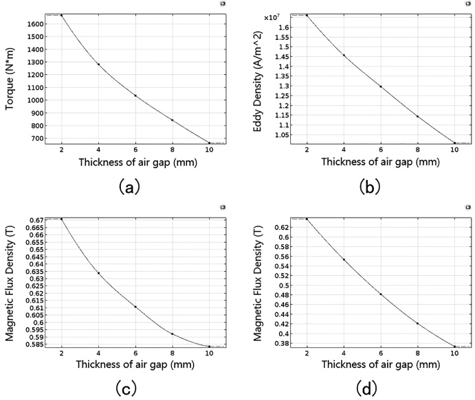
The influence of air gap thickness on coupling performance. (a) Output torque. (b) Eddy current density of copper strip. (c) The magnetic flux density on the magnet side. (d) The magnetic flux density on the internal rotor side.
The mechanical characteristic curve of squirrel cage eddy current coupling with adjustable radial air gap under different air gap thickness is shown in Fig. 11. With the increase of relative speed (input speed minus output speed), the output torque of eddy coupling increases first and then decreases. This is because with the increase of the relative speed, the induced eddy current of the copper strips increases, which makes the output torque increase. At the same time, the increase of the eddy current also leads to the increase of the blocking effect of the induced magnetic field on the air gap magnetic field and the decrease of the output torque of the eddy current coupling. In the Fig. 11, B 1 is the working point for the load torque T F = 1000 N ⋅ m and the thickness of air gap h = 2 mm; B 2 is the working point for the load torque T F = 1000 N ⋅ m and the thickness of air gap h = 6 mm; C is the intersection point of boundary line of stable operation area of eddy current coupling and line at load torque T F = 1000 N ⋅ m. When the air gap thickness is changed, the eddy current coupling can operate stably in B 1 C region at the load torque T F = 1000 N ⋅ m, which is the stable operation area of the coupling. When the air gap thickness changes from 2 mm to 6 mm, the stable working point of the eddy current coupling changes from B 1 to B 2. At this time, the output speed of the eddy current coupling changes from 1477.4 RPM to 1457.8 RPM, and the speed change rate is 1.3%, which is relatively small. The small speed change range is relative to the relative magnetic permeability of the permanent magnet yoke and the internal rotor, and the effect of relative permeability on the speed change range is studied in Section 5.2.

Mechanical characteristics of eddy current coupling under different air gap thickness.
Speed regulation performance analysis results
After the curved surface of the effect of air gap thickness and relative speed on torque of eddy current coupling shown in Fig. 6 is obtained, following the method described in Section 3.2, the torque dynamic equations (5)–(6) are solved with combination of the curved surface, and the analysis results are as follows.
The output speed and torque with time when the air gap thickness is adjusted from 2 mm to 10 mm is shown in Fig. 12. As shown in Fig. 12(a), when the thickness of the air gap changes from 2 mm to 10 mm, the output speed is gradually reduced with time, and the reduction is about 12.4 RPM. And as shown in Fig. 12(b), the torque has a big change which means that at about 3 s, there are a quick fall and a quick return to the balance. The radial air gap of the designed coupling is adjusted from 2 mm to 10 mm, and the calculation results of the speed regulation performance are shown in Table 2. The eddy current coupling has fast response and high stability, but its speed regulation range is very narrow.

The output speed and torque with time when the air gap thickness is adjusted from 2 mm to 10 mm. (a) Output speed. (b) Output torque.
Speed regulation performance
The speed regulation performance when the air gap thickness changes continuously from 2 mm to 10 mm at an interval of 2 mm is shown in Fig. 13. As shown in the Fig. 13(a) and 13(b), the speed change value and the speed regulation time increase non-linearly with the increase of air gap thickness. This is because the increase of air gap thickness will increase the air gap magnetic leakage, and the magnetic flux leakage is a nonlinear change.
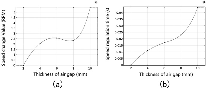
The performance curve when the air gap thickness changes continuously from 2 mm to 10 mm at an interval of 2 mm. (a) Speed change value. (b) Speed regulation time.
Figure 14 shows the results of the speed regulation performance of the eddy current coupling when the initial value of the air gap thickness is 2 mm and the variation range of the air gap thickness is 2 mm, 4 mm, 6 mm and 8 mm, respectively. It can be seen from the Fig. 14(a) and Fig. 14(b) that the speed change value and the speed regulation time increase with the change range of the air gap thickness increases. With comparison of Fig. 13(b) and Fig. 14(b), it can be noted that when the thickness of the air gap is changed from 8 mm to 10 mm and the thickness of the air gap is changed from 2 mm to 10 mm, their speed regulation time is 0.044 s and 0.048 s, respectively, which are almost equivalent. It shows that the speed regulation time of the eddy current coupling almost depends on the maximum air gap thickness.

The speed regulation performance when the initial value of the air gap thickness is 2 mm and variation range of the air gap thickness is 2 mm, 4 mm, 6 mm and 8 mm. (a) Speed change value. (b) Speed regulation time.
It can be found from the previous chapters that although the torque adjustment range of the squirrel cage eddy current coupling with adjustable radial air gap is large, its speed regulation range is very narrow, which is caused by the selection of the relative magnetic permeability of the permanent magnet back yoke and the internal rotor. In this section, the influence of the relative magnetic permeability of the back yoke and internal rotor on the speed regulation performance is studied, which provides a reference for the reasonable selection of the relative magnetic permeability of the back yoke and internal rotor to meet different speed regulation performance requirements.
By changing the relative magnetic permeability and using the FEA model in Section 3.1, the mechanical characteristic curve of the eddy current coupling for different relative magnetic permeability is obtained, as shown in Fig. 15. As shown in Fig. 15(a), for the relative magnetic permeability of the permanent magnet back yoke μ A = 1 and the relative magnetic permeability of the internal rotor μ B = 200, the stable operation area of the eddy current coupling is narrow, and for the external load T F = 400 N ⋅ m and the change of air gap thickness from 2 mm to 10 mm, the speed changes from 1485.4 RPM to 1475.9 RPM, and the change rate is 0.6%, which is relatively small. For μ A = 1 and μ B = 1, the mechanical characteristic curve of the eddy current coupling is shown in Fig. 15(b). With comparison of Fig. 15(a) and Fig. 15(b), it can be seen that when μ B is smaller, the stable operation area of the eddy current coupling is larger. This is because when μ B is smaller, in the internal rotor, there is little effect of magnetism gathering on the magnetization of the induced magnetic field, which makes the blocking effect of the induced magnetic field on the original magnetic field become smaller. Due to the reduction of the blocking effect on the magnetic field, the output speed of the eddy current coupling becomes smaller when it reaches the maximum torque, thus increasing the stable operation area. For μ A = 1, μ B = 1 and external load T F = 400 N ⋅ m, the corresponding speed change rate of air gap thickness from 2 mm to 10 mm is 9%, and for external load T F = 460 N ⋅ m, the speed change rate is 18.1%, up to a maximum value, which is larger than that for μ A = 1 and μ B = 200. This is related to the larger stable operation area caused by lower μ B Fig. 15(c) is the mechanical characteristic curve for μ A = 200 and μ B = 1. With comparison of Fig. 15(c) and Fig. 15(b), it can be seen that when μ A is larger, the eddy current coupling has a larger output torque. This is related to the larger μ A caused by the greater magnetism gathering effect of the permanent magnet back yoke on the air gap magnetic field. For μ A = 200, μ B = 1 and external load T F = 400 N ⋅ m, the corresponding speed change rate for the air gap thickness from 2 mm to 10 mm is 4.2%, which is lower than that for μ A = 1 and μ B = 1, because the increase of air gap flux density reduces the corresponding relative speed under the determined load. At the same time, it can also be noted that for the external load T F = 760 N ⋅ m, there is a maximum speed regulation range, up to 20.5%, which is greater than the maximum speed change rate for μ A = 1 and μ B = 200. Therefore, a larger μ A and a smaller μ B are helpful to improve the speed regulation range.
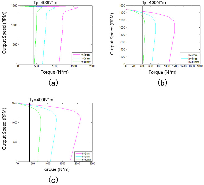
Mechanical characteristic curve of eddy current coupling under different relative magnetic permeability. (a) μ A = 1 and μ B = 200. (b) μ A = 1 and μ B = 1. (c) μ A = 200 and μ B = 1.
In this paper a novel squirrel cage eddy current coupling with adjustable radial air gap was presented, which has the advantages of compact structure, short radial dimension, no axial force and low eccentric force. The electromagnetic torque of the eddy current coupling was analyzed by the FEA software, and the influence of the structure parameters on the electromagnetic torque is analyzed, too. Then, a method to solve the dynamic equation of the eddy current coupling, based on the effect of air gap thickness and relative speed on torque characteristics, was proposed to analyze the speed regulation performance of eddy current coupling, which has the advantage of less calculation on-line due to only interpolation calculation needed based on the curve surface. Finally, the influence of the relative magnetic permeability of the back yoke and internal rotor on the speed regulation performance of the eddy current coupling was studied. Combined with the case study, the more conclusions are drawn as follows: When the air gap thickness changes from 2 mm to 10 mm, the electromagnetic torque of the eddy current coupling is reduced by 60.1%, which shows that the eddy current coupling can achieve a larger torque regulation range by adjusting the air gap thickness. The speed regulation range, the speed regulation time and the static rate of the squirrel cage eddy current coupling with adjustable radial air gap are 12.4 RPM, 0.048 s and 0.004 respectively, which shows that the eddy current coupling has the characteristics of fast response and good stability, but its speed regulation range is narrow. When the relative magnetic permeability of the permanent magnet back yoke μ
A
= 200 and the relative magnetic permeability of the internal rotor μ
B
= 1, the maximum speed change rate of the eddy coupling with adjustable radial air gap is 20.5%, which shows that the larger the relative magnetic permeability of the permanent magnet back yoke and the smaller the relative magnetic permeability of the internal rotor can improve the speed regulation range of eddy current coupling.
Footnotes
Acknowledgements
This work was supported by China University research fund No. 2010SCU2101.