
Abstract
Canned induction motors fed by inverters are widely used in pharmaceutical, chemical, and nuclear fields. It is necessary to analyse the effect of time harmonic injected by the inverter on the performance of the canned induction motor. However, the existing researches are to consider the inverter and the motor separately, without analyzing the reverse effect of the induction motor as a nonlinear active load on the time harmonics of the inverter. Therefore, this paper establishes a field-circuit coupling analysis model of the canned induction motor considering the influence of load, and studies the effect of time harmonic current under different load conditions on the electromagnetic field, eddy current loss, and temperature field of the canned induction motor. The paper first uses the analysis method to determine the relationship between the time harmonic voltage of the inverter and the time harmonic current of the motor. Then, the electromagnetic field distribution, eddy current loss, and temperature field distribution of the canned induction motor under different load conditions are calculated. Besides, the laws of time harmonic current on the electromagnetic field, can loss and motor temperature distribution are found. These research results can not only provide a meaningful reference for analysis of the canned induction motor but also provide methods for design optimization and multi-physical field modeling analysis of the canned induction motor.
Keywords
Introduction
Chemical seal pumps (CSP) are utilized to transport the toxic, corrosive, and radioactive medium, which are widely used in pharmaceutical, chemical, and nuclear fields [1,2]. The canned induction motor (CIM) is the power source of the CSP. Compared with the conventional induction motor (IM), the obvious difference of the CIM is that the stator can sleeve and the rotor can sleeve made of cylindrical, corrosion-resistance, and metal materials are installed on the inside of the stator and the outside of the rotor, respectively [3,4]. The transported media flow in the gap between the stator can sleeve and the rotor can sleeve. The canned sleeves can isolate the damage of the media to the stator and rotor, and then they also play a sealed role. The structure of the canned induction motor is shown in Fig. 1.
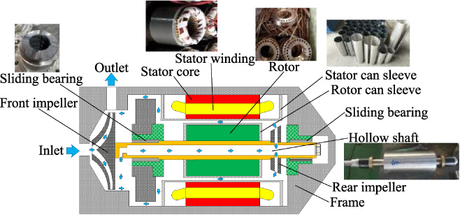
The structure of the CIM.
The most popular research is about the can loss in CIM [5–8]. The reason is that the cans have a high conductivity as metal materials, thus the electromotive force (EMF) induced by alternating magnetic field generates the eddy current and loss in them. More importantly, the eddy current can also react to the magnetic field of the motor, resulting in a more complicated magnetic field distribution of the CIM. Also, the stator and rotor can losses could increase the temperature and damage the insulation system of the motor [9]. The researchers have focused on the above problems of the CIM.
In the electromagnetic field analysis of the CIM, a three-dimensional finite element model of the CIM was established, and its end leakage magnetic field and end leakage resistance were calculated in [10]. An et al. investigated the distribution of electromagnetic field under the condition of the stator asymmetric winding of the CIM, and the results show that compared with the case of symmetrical stator windings, the air gap magnetic density amplitude and total harmonic distortion rate of asymmetric windings are significantly deteriorated [11]. In [12], Yu et al. proposed an analytical model of the concentric cylindrical rotor layer structure and used this model to analyze the electromagnetic field of the CIM, while also considering the slotting effect and saturation of magnetic circuit. The results show that the existence of the cans changes the distribution rule of the air gap magnetic field.
In terms of the can loss, the eddy current loss of the canned sleeves in the CIM under starting, no-load, and rated load conditions were obtained by the two-dimensional finite element steady-state field and the calculation formula of the harmonic loss, which provides a reference for the performance analysis and design of the motor [13]. In [14], Tinni et al. proposed an equivalent circuit of the IM with a non-magnetic canned sleeve and analyzed the performance of the CIM using this equivalent circuit. This equivalent circuit helps to separate the various losses of the CIM, the sensitivity analysis, and optimization of the parameters to the motor losses. In [15], the can loss and the circulating current loss between the end structures were calculated in detail. In addition, the factors affecting the loss were analyzed and a method to reduce the canned loss was proposed.
In the temperature calculation, the temperature field of the CIM was analyzed in [16], and the results show that water friction loss does not affect the location of the motor peak temperature and the winding temperature distribution trend.
The previous documents indicate the research direction and provide a reference for further research on the CIM. To improve the operational efficiency and adjust the flow rate of the CSP, the CIM is fed by an inverter. The time harmonic brought by the inverter could affect the CIM performance, and the researchers conducted some works on this topic. In [5], the can loss considering penetration depth of the harmonics was calculated, and the effects of different can materials on the eddy current loss of the stator and rotor, magnetizing current, and motor performance were analyzed and compared. In [17], Li et al. analyzed the influence of the time harmonics on the eddy current loss of the rotor sleeve. However, the influence of the motor load on the time harmonic current is rarely considered in existing researches [18,19]. In fact, as the nonlinear active load of the inverter, the motor has a reverse effect on the time harmonic current, thus the motor and inverter should be treated as a system for analysis. Therefore, the influence of time harmonic current considering load conditions on the performance of the CIM is studied in this paper based on the field-circuit coupling calculation model. The relationship between the time harmonic voltage of the inverter and the time harmonic current of the motor is obtained. Compared with previous studies, these results not only improve the calculation accuracy of the CIM performance, but also provide a meaningful reference for the analysis, design, and optimization of the CIM fed by the inverter.
The paper is organized as follows. The coupling analysis model of the CIM is established in Section 2. In Section 3, the equivalent circuit of the CIM considering space harmonic is derived, and the relationship between inverter time harmonic voltage and motor time harmonic current is obtained. Besides, based on the field-circuit coupling analysis model, the influence of time harmonic current on the electromagnetic performance of the CIM under different load conditions is compared. In Section 4, the temperature prediction of the CIM is presented. Section 5 concludes the paper.
The CIM is similar to an IM, which consists of a stator core, a stator wingding, a rotor, a shaft, a stator can and a rotor can. The bearing of CIM is a sliding bearing, which is usually made from silicon carbide. The rotor bar is made from a copper-zinc alloy, which can reduce the rotor ohmic loss and improve efficiency [20]. The basic parameters of the motor are shown in Table 1.
Basic parameters of the CIM
Basic parameters of the CIM
To analyze the effect of time harmonic current on the CIM under different load conditions, the field-circuit coupling analysis model is established as shown in Fig. 2. To simplify the calculation, the electromagnetic field of the motor does not take into account the influence of the displacement current [21]. The control equation and boundary condition of the electromagnetic field model are as follows [22,23]:
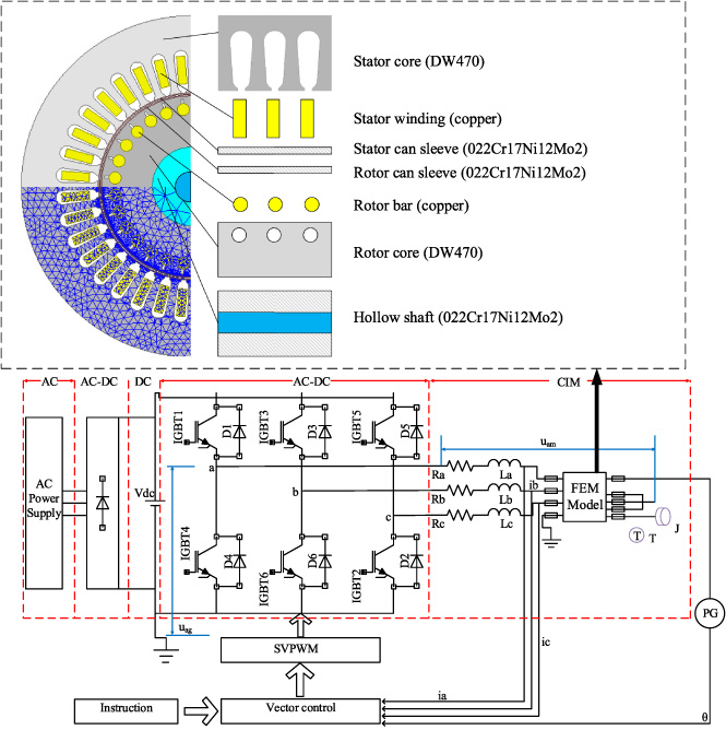
The field-circuit coupling analysis model of the CIM.
To verify the correctness of the analysis results, the prototype is tested in this paper. The equipment needed in the test is shown in Fig. 3. As the purpose of this research is to explore the effect of time harmonic current on the CIM performance under different load conditions. Therefore, the motor performance of the three working conditions of the rated load, the 85% rated load, and the 70% rated load are tested. The specific test process is as follows: the rated voltage with rated frequency is applied to the motor by the controller, the load is adjusted by the flow regulator, the voltage and current of the motor are measured by the power analyzer, and the torque and speed of the motor are obtained by the speed and torque sensor according to IEC60034-2. In addition, the finite element calculation results without a control circuit are also calculated for comparison with the coupled model results.
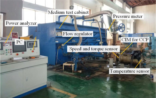
Experimental equipment of the CIM.
The test data and calculated results are shown in Table 2. It can be seen from Table 2 that the calculated result using the field-circuit coupling model is closer to the experimental value than that of the finite element calculation without the control circuit, which illustrates the accuracy of the coupling model calculation.
Test data and simulation result
Relationship between time harmonic voltage of the inverter and time harmonic current of the motor
When the CIM is fed by an inverter, the supply voltage contains rich harmonic components. The induced EMF also contains abundant harmonics, as the air gap flux density waveform of the motor is generally non-sinusoidal. The interaction between these induced EMF harmonics and the voltage harmonics generates the harmonic currents in the stator windings [17]. When the motor is under different load conditions, the saturation of the magnetic field is different, resulting in different air gap magnetic fields and EMF distribution. Thus, the time harmonic currents of the motor are different.
The harmonic current generated by the fundamental voltage is first analyzed. Assuming that the induced EMF of the motor contains only odd harmonics, the equivalent circuit of the CIM considering fundamental voltage is shown in Fig. 4.
Equivalent circuit of the CIM considering fundamental voltage.
In Fig. 4, U 1(ω1, θ U 1 ) is the output fundamental voltage of the inverter, ω1 is the angular velocity of the fundamental voltage, θ U 1 is the initial angle of the fundamental voltage. E 1(ω k , θ Ek ) is the EMF with angular velocity ω k , which is induced by the rotating magnetic field generated by the fundamental voltage in the stator winding, where ω k = kω1. The initial angle of the E 1(ω k , θ Ek ) is θ Ek . X 2, k , R 2, k ∕s k , X c, k , are respectively the rotor leakage reactance, rotor equivalent resistance, and the canned sleeve leakage reactance of the referred stator winding corresponding to ω k , k = 1,3,5,7, ….
The harmonic current generated by the fundamental voltage is
Equation (2) shows that the induced EMF harmonic and the fundamental voltage can match each other only when they have the same angular velocity, and the effect depends on the relationship between the angle between the fundamental voltage and the induced EMF harmonic. Therefore, in the stator winding of the motor, besides the fundamental current, there are also other odd harmonic currents caused by the induced EMF harmonics.
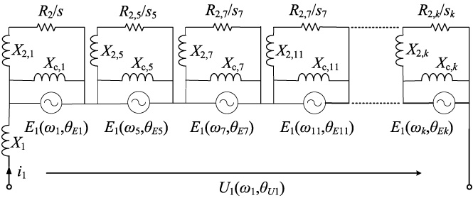
Similarly, the equivalent circuit of the CIM considering harmonic voltage is shown in Fig. 5.
Equivalent circuit of the CIM considering harmonic voltage.
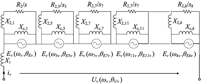
In Fig. 5, U 𝜈(ω𝜈, θ U𝜈) is the harmonic voltage of the inverter, ω𝜈 = 𝜈ω1, θ U𝜈 is the initial angle of the 𝜈th harmonic voltage. E 𝜈(ω k𝜈, θ Ek𝜈) is the EMF with angular velocity ω k𝜈, which is induced by the rotating magnetic field generated by the 𝜈th harmonic voltage in the stator winding. θ Ek𝜈 is the initial angle of the E 𝜈(ω k𝜈, θ Ek𝜈).
Then the relationship between the time harmonic voltage of the inverter and the time harmonic current of the motor is
Equation (3) shows that the 𝜈th induced EMF with ω𝜈 can match the harmonic voltage with the same angular velocity and the same order, and the effect still depends on the position between the two initial angles. When the angular velocity, initial angle, and amplitude of the 𝜈th harmonic voltage and the 𝜈th induced EMF are the same respectively, there is no 𝜈th harmonic current in the motor windings. When the load conditions of the motor are different, the saturation of the motor will inevitably cause changes in the amplitude of the induced EMF and the initial phase angle, resulting in different time harmonic current components.
The inverter output voltage and induced EMF waveforms under three load cases are calculated by the field-circuit coupling analysis model, which are shown in Figs 6 and 7, respectively. Then, according to Eq. (3), the current waveforms are obtained and shown in Fig. 8.
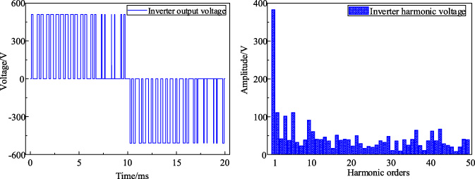
Inverter output voltage waveform and harmonics.
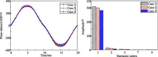
Induced EMF waveforms and harmonics under three load conditions.
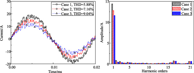
Current waveforms and harmonics under three load conditions.
From Fig. 8, when the motor load decreases from 20 N ⋅ m in case 1 to 14 N ⋅ m in case 3, the root mean square (RMS) of the current decreases from 14.4 A to 11.6 A. However, the total harmonic distortion (THD) of the current increases from 5.88% to 9.04%, which ups by 53.74%. The reason is that the saturation effect weakens as the load decreases, resulting in the induced EMF harmonics to be decreased, and the harmonics in the supply voltage cannot be offset, thus the THD of the current increases.
Magnetic flux density analysis
The magnetic flux density of the air gap (B air), the stator can (B sc) and rotor can (B rc) under three load conditions were obtained by the field-circuit coupling model. The results are shown in Figs 9–11.
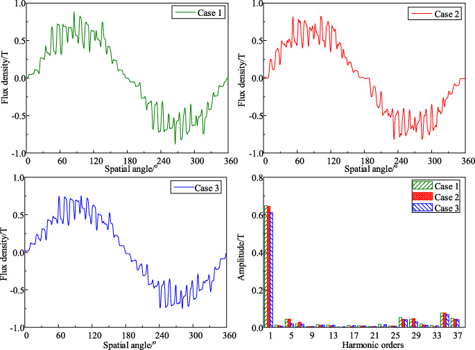
Magnetic flux density and harmonics in the air-gap.
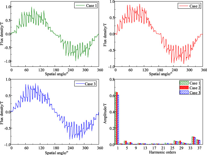
Magnetic flux density and harmonics in the stator can sleeve.
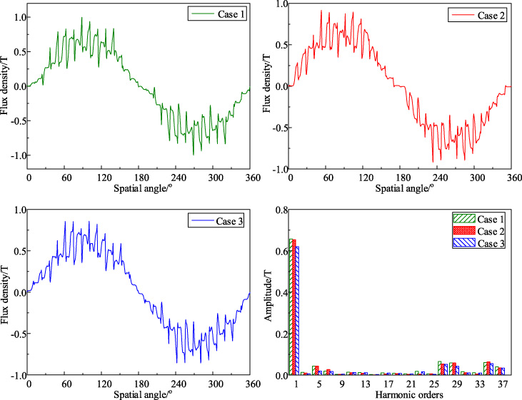
Magnetic flux density and harmonics in the rotor can sleeve.
In Figs 9–11, it can be observed that the waveforms of B air, B sc, and B rc are not smoothly sinusoidal but are fluctuating. Also, the 5th, 7th, 27th, 29th, 35th, 37th harmonics are the main harmonic components of the magnetic flux density, where 27th and 29th harmonics come from first-order rotor tooth harmonic, and 35th and 37th harmonics are from first-order stator tooth harmonic. In these three cases, the fundamental magnetic density of the motor decreases with the load decreases. The fundamental amplitude of B air is 0.65 T, 0.64 T, and 0.61 T, respectively. The fundamental amplitude of B sc is 0.64 T, 0.64 T, and 0.60 T, and the fundamental amplitude of B rc are 0.63 T, 0.62 T, and 0.60 T, respectively. Besides, the amplitudes of the 5th, 27th, 35th, and 37th harmonics all decrease with the load decreases. However, in case 2, the amplitudes of the 7th and 29th harmonics are larger than those in case 1 and case 3.
The stator can loss and rotor can loss are calculated using the field-circuit coupling analysis model and Eq. (4) [17].
The harmonic losses in the stator can and rotor can under the three loads are shown in Table 3.
Eddy-current losses in can sleeves under three loads
In Table 3, the loss in the stator can are mainly the fundamental loss in three load conditions, and it accounts for 98.5%, 97.9% and 98.7% of the stator can loss, respectively, whereas 91.4%, 91.1% and 91.7% of the rotor can loss is the stator tooth harmonic losses, respectively. The stator can fundamental loss in case 1 is slightly higher than that in case 2 and case 3 as the fundamental flux density of the stator can in case 1 is higher than that in case 2 and case 3. However, because the slip is slight, the rotor can fundamental loss is almost zero. Since the relative velocity between rotor tooth harmonics and the rotor is close to zero, the rotor tooth harmonic losses in the rotor can are also unimportant.
The total eddy current losses of stator can and rotor can under the three load conditions are shown in Fig. 12. From Fig. 12, the stator can loss and the rotor can loss are 1153.5 W and 310.5 W in case 1, respectively. In case 2, the stator can loss and the rotor can loss are 1039.4 W and 209.4 W, respectively. In case 3, the stator can loss and the rotor can loss are 947.4 W and 195.9 W, respectively. Compared with case 1, the stator can losses of case 2 and case 3 decreased by 9.89% and 17.87%, respectively, and the rotor can losses decreased by 32.56% and 36.91%, which show that the rotor can loss is more sensitive to the change of harmonic currents compared with the stator can loss.
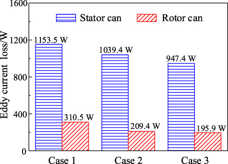
The can loss under different load conditions.
Temperature calculation method
As the temperature distribution has an important influence on the life and driving characteristics of the CIM [24], the thermal field of the CIM is studied by a method combining computational fluid dynamics (CFD) and electromagnetic thermal iterative calculation. The flow chart of the calculation is shown in Fig. 13.
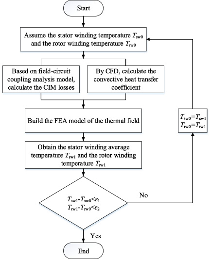
The flowchart of the temperature calculation.
When solving the thermal field, two aspects worthy of concern are the convective transfer coefficient and the loss calculation. As shown in Fig. 13, the convective heat transfer coefficient of the medium is calculated by ANSYS CFX for given inlet velocity, medium temperature, and outlet pressure (1 atmospheric pressure). Then, the convective transfer coefficient is applied to the thermal model. In addition, to consider the coupled electromagnetic and thermal effect, the electromagnetic-thermal iteration is used to obtain an accurate temperature distribution. It is assumed that the initial temperature of the stator winding and the rotor bar is the medium temperature, when the difference between the calculated result and the initial value is less than the set error, the calculation ends. Generally, the maximum allowable temperature error is set to 1 °C.
As the mesh quality and element quantity of the finite element model can affect the calculation results, the independence of the mesh is verified. From Table 4, the increase in element number can induce an increase in calculation time. By comparing the winding temperature and calculation time of 5 different element number models, the calculation model with the total element number of 157117 is adopted. Where the element number of frame is 2100, the element number of the stator core is 44550, the element number of winding is 15600, the element number of the stator can sleeve is 1300, the element number of the rotor can sleeve is 5541, the element number of the bar is 15476, the element number of rotor core is 15785, the element number of the shaft is 9000, the element number of the impeller is 42765. The mesh of the main components in the CIM is shown in Fig. 14.
Mesh independence verification
Mesh independence verification
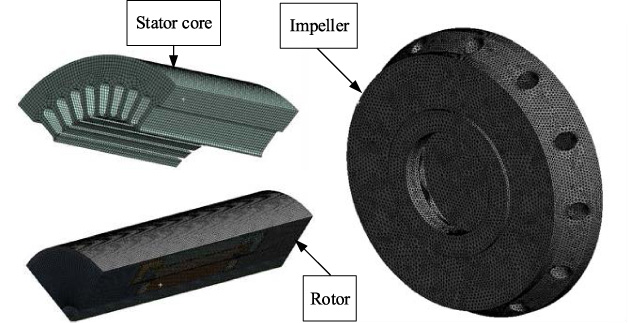
The mesh of the main components in the CIM.
The component temperatures of the CIM in case 1, case 2, and case 3 are presented in Table 5. It is worth noting that the medium temperature corresponding to different loads is different.
The temperature of CIM under different load conditions
The temperature of CIM under different load conditions
From Table 5, the highest and lowest temperature appear in stator winding and rotor can sleeve, respectively. In case 1, the maximum temperature rise of the motor is 28.9 °C. In case 2 and case 3, the maximum temperature rise of the motor is 26.2 °C and 11.2 °C, respectively. The temperature rise of the motor decreases with the decrease of the load, which is consistent with the calculated results of the can loss. It can be seen from the temperature calculation results that the designed temperature rise of the motor is low so that the motor can not be damaged due to overheating when transporting a high-temperature medium. This is why the medium temperature settings are different for the three cases. Therefore, when the CSP transports the high-temperature medium, the motor should run at reduced power.
To determine the temperature distribution trend of the CIM, the temperature of the components is studied, as shown in Fig. 15. From Fig. 15, the highest and lowest temperatures of the stator core are 115.9 °C and 99.9 °C in case 3, respectively. The temperature in the stator tooth is higher than that in other parts of the stator, because the stator tooth is close to the winding end. For the stator winding, the highest and lowest temperatures are 118.2 °C and 109.8 °C, respectively. The temperature in the end part is higher than that in other parts, because the heat generated at the end of winding can only be transferred to other regions through the air. Different from the stator winding, the temperature distribution of the rotor bar shows a middle height, and both ends gradually decrease. The highest and lowest temperatures of bars are 100.6 °C and 99.9 °C, respectively. The reason is that the heat generated at the bar end can be transferred to the medium through the end of the rotor can.
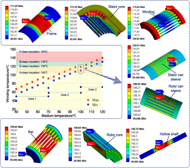
The temperature field distribution of CIM under different load conditions.
In addition, the temperature distribution of the motor under different medium temperatures is calculated. The results show that for the same case, the temperature rise of the motor is almost constant when the medium temperature is different. However, for different cases, even if the medium temperature is the same, the temperature rise of the motor is still different.
In this paper, the effects of time harmonic currents considering the load conditions on the CIM electromagnetic field, the can loss, and temperature field are studied based on the field-circuit coupling analysis model and experiments. Some conclusions are obtained as follows: The induced EMF harmonics can match the voltage harmonics with the same angular velocity and the same order, and the effect depends on the angle between them. When the motor load torque is reduced from 20 N ⋅ m to 14 N ⋅ m, the fundamental amplitude of the air gap flux density decreases from 0.65 T to 0.61 T by 6.15%, and the fundamental amplitude of the stator can flux density decreases from 0.64 T to 0.60 T by 6.25%, and the fundamental amplitude of the rotor can flux density decreases from 0.63 T to 0.60 T by 4.76%. The stator can loss decreases from 1153.5 W to 947.4 W by 17.86%, and the rotor can loss decreases from 310.5 W to 195.9 W by 36.91% when the motor load torque decreases from 20 N ⋅ m to 14 N ⋅ m, which shows that the rotor can loss is more susceptible to harmonic current than the stator can loss. The medium temperature has little effect on the temperature rise of the motor when the load is constant. However, the maximum temperature rise of the motor decreases with the load decreases. Therefore, when transporting a high-temperature medium, to meet the temperature limit, the motor should run at reduced power.
Footnotes
Acknowledgements
This work were supported by the National Science and Technology Major Project under Grant 2017ZX02201005-002 and Provincial Science and Technology Major Project of Liaoning in China under Grant 2019JH1/10100016.