
Abstract
This paper investigates the damping and demagnetization effect of an electromagnetic buffer (EMB) under impact load. The motional eddy currents are calculated first, and the Ampere circuital theorem is employed to calculate the induced magnetic field. The demagnetization effect is formulated by the magnetic Reynolds number with a correction coefficient k m. Following this, the time-step finite element (FE) model of the buffering system is constructed based on the nonlinear B–H curve. The accuracy and feasibility of the FE model is preliminarily verified by small-scale impact test. The characteristics of damping displacement, velocity, damping force and damping coefficient are obtained. Then, the demagnetization effect is analysed by eddy current, magnetic field distribution, through the intensive impact load test at room temperature and time-step FE model. The value of k m is obtained through the intensive impact test and the simplified expression of critical velocity. The results show that the demagnetization effect is obvious with the increase of velocity. By introducing the correction coefficient of magnetic Reynolds number, the eddy current demagnetization process is more realistic.
Introduction
The impact load exists widely in engineering practices, such as the non-contact impact of submarines, shooting processes, and landing of aerospace vehicles. Generally, it is essential to eliminate or weaken the shock to ensure the performance of equipment under impact load. For this purpose, the application of viscous damping based on cushioning materials has been studied vigorously over the past two decades, yielding innovations such as the spring-Buffer [1,2], oil buffer [3], magnetorheological buffer [4,5], and special structure buffer [6,7].
The biggest merit of employing eddy current is the possibility of creating damping, but without any direct contact or friction with the apparatus. Different from other damping techniques, there is no leakage problem in electromagnetic buffers (EMBs) due to the absence of fluid, which is beneficial as fluid leakage can increase the stiffness of the buffer system.
The eddy current is induced in such a manner that the conductor either experiences a time-varying magnetic field or moves in a static magnetic field. Meanwhile, the magnetic field induced by the eddy current is opposite to the external magnetic field that produces the eddy current. Through the interaction of the static field and the induced field, the damping force opposite to relative motion is generated. Consequently, the induced current is eventually converted into heat due to the internal resistance of the conductive material [8,9]. At present, the study on EMBs mainly focuses on low-velocity applications, such as suspension and vibration control. Some researchers have carried out both analytical and experimental deep studies on their working principles and damping characteristics. However, the mechanism of electromagnetic damping under high-velocity conditions is promising, yet preliminarily unexplored.
Ebrahimi et al. [10–12] introduced the modelling, simulation, and testing of a new cylindrical linear eddy current buffer for a vehicle suspension system. In subsequent works, the analytical model considering the skin effect was obtained, and the accuracy of the theoretical model was verified by low-velocity experiments. Wen et al. [13] described the assessment and control of pedestrian-induced vibration of a footbridge using an eddy current tuned mass damper (TMD) with a mode-by-mode approach. Then, the theoretical potential was analysed by a case in Australia, while Lu et al. [14] used eddy current TMD to improve the anti-vibration performance of high-rise buildings with laboratory tests and field tests. To describe the braking torque more reasonably at high velocities for a disc eddy current braking system, Kapjin and Kyihwan [15–17] proposed the assumption that the magnetic Reynolds number is an exponential. Sharif et al. [18] analysed the magnetic field distribution on the surface of a cylindrical rotor, and developed the magnetic Reynolds number by adding an exponent obtained by the limit of power loss. Zhou et al. [19] introduced the concept of anti-magneto-motive force to develop the eddy current brake model, in which the eddy current demagnetization and the temperature effect were presented.
Since the previous EMB applications were mostly used in low-velocity and low-load situations, the mechanism of eddy current damping and demagnetization under impact load and high velocity has not been studied systematically. In this paper, a cylindrical linear EMB with composite tube structure is tried to be used in intensive impact load situations. The damping and demagnetization characteristics are analysed by means of small-scale impact test, intensive impact test and time-step FE method at room temperature. The correction coefficient of magnetic Reynolds number is proposed to indicate the degree of eddy demagnetization. Considering the non-uniformity of demagnetization effect, the correction coefficient value is obtained through the intensive impact test and simplified expression of critical velocity.
Models and methodology
The static field
Figure 1 illustrates the structural schematic of the studied cylindrical linear EMB, which mainly consists of two parts: (1) the primary part, which consists of a moving rod combined with a sequence of ring-shaped, axially magnetized permanent magnets separated by pure iron poles, and (2) the secondary part, which consists of an outer tube and an inner tube. The relative motion of the primary and secondary induces motional eddy currents in the inner tube and outer tube. According to Lenz’s law, the magnetic field generated by the eddy current will interact with the primary external magnetic field, which tends to stop the EMB. Figure 2 exhibits the layout of the permanent magnets, which are oriented with magnetic poles of the same polarity facing each other to increase the amount of magnetic flux entering the secondary. The thick bold arrow shows the direction of flux line. The inner tube has high conductivity while the outer tube has high magnetic permeability. Compared with the single design, the composite tube structure provides more efficient flux utilization and higher eddy current generation.
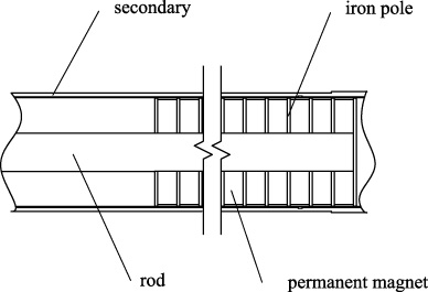
Schema of the studied EMB.

Configuration of the EMB.
The induced motional eddy current is affected by magnetic saturation, thermal effect, demagnetization, as well as skin effect between the iron poles and the outer tube, thus it is difficult to calculate under intensive impact load. Therefore, we suppose that the magnetic permeability and conductivity of the electromagnetic material remain unchanged as the temperature changes slightly.
It is not appropriate to calculate the magnetic flux density by the dipole moment model since the axial length of the permanent magnet is shorter than the diameter. The equivalent volume current density and equivalent surface current density proposed by Furlani [20] can be used to replace a cylindrical magnet. The equivalent current density can produce the same air-gap magnetomotive force outside the iron poles as the permanent magnet, given by
The eddy current generated by the original magnetic field in the inner tube and outer tube is obtained by
At present, only the influence of the magnetic field induced by eddy current has been considered to explore the demagnetization effect of the EMB. However, the quiescent operation point drop of the permanent magnet also affects the damping force, especially in the parameter analysis. Therefore, it is essential to consider the influence of both to study the mechanism of demagnetization.

Magnetic field distribution generated by different excitations. (a) Original magnetic field. (b) Magnetic field induced by eddy current. (c) Resultant magnetic field.
The distribution of the air-gap magnetic field varies with the motion state of the EMB driven by intensive impact load. The time-varying eddy current magnetic field interacts with the original magnetic field, resulting in the distortion of magnetic lines. Figure 3(a) denotes the magnetic flux pattern with no relative motion between primary and secondary. The magnetic field induced by eddy current and the resulting pattern are illustrated in Figs 3(b) and 3(c), respectively. When the primary motion occurs, the magnetic density increases in the direction away from the velocity. Therefore, to get the real net magnetic field, the magnetic field generated by the eddy current must be analyzed.
It is assumed that: (1) the radial component of the magnetic field is uniformly distributed in the air-gap and the inner tube, and (2) the magnetic field strength of the iron poles and the outer tube is zero. The Ampere circuital theorem is used to calculate the eddy current magnetic field:
It can be seen from Eq. (11) that R
m increases in proportion to the velocity. The magnetic Reynolds number R
m and the net air-gap flux density are in accordance with the following relationship. When there is no relative motion, the induced eddy currents and, consequently, the R
m are equal to zero. Thus, the net air-gap magnetic induction (B
r) is equal to B
0. After the relative velocity occurs, the B
r decreases with the R
m. The R
m is infinite, and B
r equals zero with the infinite velocity occurring. The net air-gap flux density can be assumed as
The motional electromotive forces are generated in the inner tube and the outer tube. The eddy current damping force of the two magnets at the same pole resulting from the motional electromotive forces is obtained by
When the structure and material parameters of the EMB are determined, the most significant factors affecting the damping force are velocity and magnetic induction strength. When the demagnetization effect is not considered, the damping force becomes a linear function of velocity at high or low velocity. The damping coefficient will become constant. When the velocity is small, the demagnetization effect is weak and the damping force increases linearly with the velocity in the real buffering process. The growth rate of damping force decreases gradually as the velocity continues to increase. When the velocity reaches the threshold value, the damping force begins to decrease because of the enhancement of demagnetization.
In this paper, we use the transient analysis method to establish a time-step FE model to study the damping characteristics and demagnetization effect under impact load. A more realistic, transient analysis model has been formed to reflect the impact buffering process. Sintered NdFeB is selected as the permanent magnet for the studied EMB because of its excellent properties, such as high remanence, high magnetic energy product, high coercive force, lightweight, and low cost. Since the test temperature is lower than 10 °C, the demagnetization curve of the grade N52 and N38 is shown in the Fig. 4.
Then, the actual demagnetization curve is imported into the transient analysis model. The nonlinearity magnetization of the iron pole is fully considered. The magnetic B–H curve of the iron poles is established to accurately simulate the actual magnetic saturation phenomenon, as shown in Fig. 5.

Demagnetization curve of sintered NdFeB.

B–H curve of iron poles.
The nonlinear effect of the magnetization curve is considered, but the hysteresis characteristic is ignored. The hysteresis loop of the iron poles is very narrow and the coercive force is low due to the soft magnetic material. Thus, the simplification here improves the calculation efficiency within the acceptable error range. The inner tube and the outer tube are fixedly connected. The moving rod and the iron poles are connected by rigid contact, as well as the iron poles and the permanent magnet. There is an air-gap, through which the magnetic flux passes, between the primary and the secondary to realize the transmission of damping force and energy.
The magnetic induction of each iron pole near the moving rod is equal to zero, which is maximized outside the iron pole. Outside the EMB, although the magnetic field is infinitely extended, considering that the magnetic field outside the secondary is weak, the vector potential is set as 0 on the edge of the transient analysis model.

Local diagram of the transient analysis model.
After loading the impact load, which can be obtained through experiment or pressure test, the time-step analysis model can be obtained. Figure 6 depicts the local diagram of the transient analysis model. The realistic transient analysis model obtained by FE analysis is used to calculate the electromagnetics and resistance characteristics of the EMB system, including eddy current distribution and magnetic field distribution, damping force, buffering velocity, and displacement. Take primary motion as an example, that is, the primary part is subject to the intensive impact load while the secondary part remains stationary. Due to the relative movement between the primary and secondary of the EMB, the damping force is generated. So is secondary motion.
In order to verify the accuracy of the time-step FE model and study the impact buffering process, a small-scale impact test is carried out in laboratory to preliminarily analyze the damping characteristics. After that, a larger prototype is made and the demagnetization law is analyzed through the intensive impact load test.
The small-scale impact test platform is mainly composed of the impact load generating device and a small-scale EMB. The impact load is generated using an air compressor, as shown in Fig. 7. The small-scale EMB and test system is illustrated in Fig. 8. After the compressed air is released, the internal hammer acts on the mass block. An acceleration sensor is installed on the side of the mass block. The force sensor is connected to the primary through the thread on the motion rod. The laser displacement sensor is oriented vertically to the mass, so as to obtain accurate displacement data.
Impact load generating device.

Small-scale impact test platform.
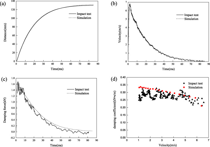
Buffering displacement (a), buffering velocity (b), damping force (c), damping coefficient (d).
The grade N38 is used in the small-scale EMB. The impact test results and FE simulation data are shown in Fig. 9. It can be seen that the displacement, velocity and damping force of the experiment and simulation are very consistent. It shows that the method of establishing the FE model has high credibility. The damping coefficient gradually decreases with increasing velocity, as shown in Fig. 9(d). It shows that the demagnetization effect gradually becomes more obvious as the velocity increases.
However, the velocity of the small-scale EMB is still at a low level, which is not enough to cause further demagnetization to reach the critical velocity. Therefore, it is necessary to manufacture a larger prototype to measure the damping characteristics under intensive impact load. Then, combined with time-step FE model and theoretical analysis, the demagnetization effect is studied.
Dynamic model of intensive impact test platform
First of all, considering the difference from the small-scale EMB scheme, the time-step FE model study under intensive impact load is carried out according to the modeling method in Section 2.4. A buffering system was selected to obtain damping and demagnetization characteristics. The EMB is placed in the dynamic buffering system, which mainly includes intensive impact load, recuperator force, friction force, etc. According to the pressure change in the pressure bore, Lagrange quadratic interpolation is used to obtain the average pressure in the bore at any time. Then, the intensive impact load is obtained, as shown in Fig. 10. The maximum impact force is up to 2700 kN, and the action time is about 10 ms.
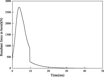
Intensive impact load.
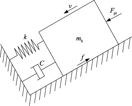
Mechanical model of the damped structure with EMB.
Moreover, the recuperator force is applied, which returns the EMB to the initial position, given by
For the convenience of analysis, the resultant force opposite to the direction of the intensive impact load is given by
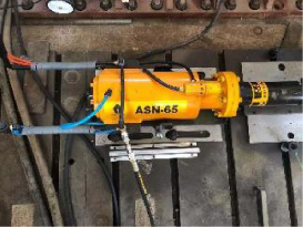
The EMB is tested under intensive impact load, as shown in Fig. 12(a). The ring-shaped sintered N52 permanent magnet consistent with the FE model was selected. The prototype EMB is placed on an impact test platform. The primary can realize buffering and resetting motion on the impact test platform, forming a single degree of the freedom motion system.
In the impact test, the FASTCAM Mini UX50 high-velocity photographic video is used to collect image information of buffering motion, as demonstrated in Fig. 12(b). By adding a mass block, the video reduces the fluctuation of test results caused by impact load. With frame rates up to 800 000 at reduced resolution, the video can meet the demanding requirements of impact environment. The displacement and velocity of the recoil movement are analyzed by ProAnalyst software. The piezoelectric quartz test-force-ring sensor is attached to the end of the rod. The ceramic shear accelerometers is installed on the impact test platform where it moves with the primary. The test data is obtained by the data acquisition system via charge amplifier.
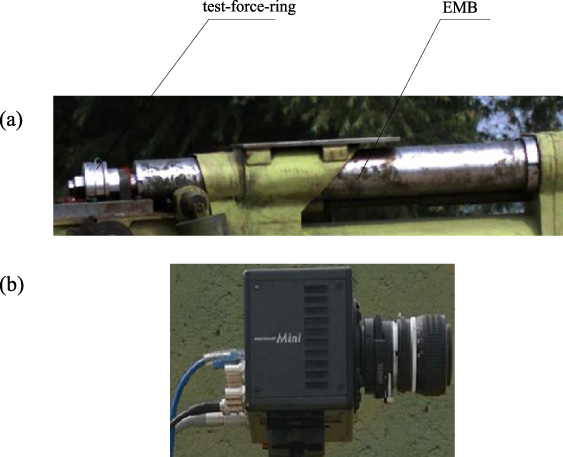
Experimental set-up for EMB. (a) Fabricated prototype for proof of concept. (b) High-velocity photographic equipment.
The established transient analysis model is numerically simulated and compared with the experimental results, as shown in Fig. 13. The buffering displacement and velocity obtained by the experiment are in good agreement with those calculated by the FE method under intensive impact load. After the impact load is completed, the moving rod still extends out the secondary of the EMB. The longer the moving rod extends, the greater the vibration of the impact test platform on it, resulting in the fluctuation of the test displacement and velocity. As depicted in Figs 13(c) and 13(d), the error of the displacement curve of the reset motion is small, the experimental results of buffering acceleration are consistent with the FE method.
The measurement errors of maximum displacement, buffering completion time and maximum velocity and the velocity peak time are very small between the test mean and the FE method, as listed in Table 1. Therefore, the established transient analysis model can meet the requirements of the impact buffering analysis. Moreover, the peak value of the damping force obtained from the experiment appears at 7.5 ms, which is earlier than the peak speed time. It is indicated that the FE model can basically reflect the dynamic and electromagnetic characteristics of the EMB under impact load, which provides a reference for the subsequent design.
Measurement errors
Measurement errors
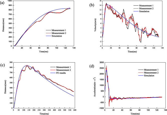
Comparison of experimental (a) buffering distance–time, (b) velocity–time, (c) buffering and reset motion velocity–time, (d) acceleration–time characteristics with those calculated by simulation.
As demonstrated in Fig. 14(a), the radial distribution of the inner tube eddy current is approximately uniform, and it exhibits periodic changes because of the same polarity of the permanent magnets facing each other. Because of the current generated by the outer tube, the edge effect of the inner tube has a weak influence on the eddy current distribution. Figure 14(b) shows that the radial eddy current density of the outer tube decreases gradually to zero from inside to outside. The eddy current can be obviously reduced at 15 ms, which indicates that demagnetization effect can not be ignored.
The radial component of the air-gap flux density with velocity from 0 to 2τ in Fig. 2 during primary motion and secondary motion are shown in Fig. 15. The radial magnetic flux density presents a time-varying regular distribution under the intensive impact load. When the primary is subjected to the intensive impact load, the radial magnetic field moves with the position in the manner of a traveling wave since the original magnetic field is moving. When the secondary is impacted, the primary field remains stationary. The radial magnetic field will twist without moving. The flux is significantly reduced along the moving direction and increased along the opposite direction when the velocity gradually increases from 0 m/s to 12 m/s. As the velocity continues to increase, the radial magnetic flux distribution is triangular and appears to fall at all locations. The reason is that the magnetic field induced by eddy currents generates an armature reaction during the buffering process, which in turn distorts the original magnetic field.

Eddy current density of (a) inner tube and (b) outer tube.
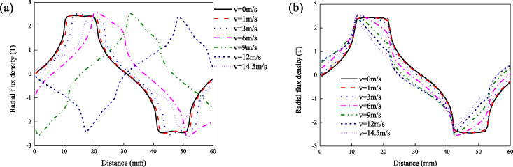
Radial magnetic flux density: (a) primary motion; (b) secondary motion.
The residual magnetic induction (B
r0) and coercive force (H
c) after magnetization are determined. The quiescent operation point of permanent magnets affected by their own demagnetizing field is not distributed at (0, B
r0), which is located at P
1 (H
p1, B
p1) as obtained by the intersection of the demagnetization curve and the rate permeance wire of the external magnetic circuit. The magnetic resistance of the ferromagnetic material cannot be neglected. When the EMB is designed, the ferromagnetic material is not allowed to exceed the magnetic saturation point. Therefore, the permeance of the external magnetic path is calculated by using the permeability at the saturation point. The air-gap magnetic field can be obtained by calculating the main flux and the air-gap area. After the EMB size is determined, the quiescent operation point will not move if the air-gap width remains unchanged. The dynamic operation point of permanent magnet P
2 (H
p2, B
p2) is controlled by the applied external demagnetizing field H
e, and the magnetic field intensity can be obtained by Eq. (17) as follows:
It can be seen that the dynamic operation point of the permanent magnet is not fixed under the intensive external field caused by impact load. Rather, it varies along the B–H curve with the change of the external magnetic field. The recoil line coincides with the demagnetization curve and there is no irreversible demagnetization. The simplified calculation uses the same recoil permeability as the FE analysis, expressed as μ0μr. The recoil permeability can be regarded as a constant due to the superior demagnetization characteristics of the NdFeB alloys. The following relationship can be obtained from Fig. 16:
The value of k m conforms to the Eq. (19). In fact, the net magnetic field indicated by the exponential mode satisfies the boundary conditions. The magnitude of the demagnetization rate is guaranteed by the introduction of k m. The demagnetization effect varies with the complex electromagnetic environment; therefore, the value of k m fluctuates with the eddy current field. The permanent magnet is not uniformly demagnetized under the action of eddy current demagnetization caused by intensive impact load. There is a large error when Eq. (19) is used to solve the value of k m. In order to ensure accuracy, the non-uniformity of demagnetization is fully considered. The value of k m is obtained through the intensive impact test and the simplified expression of critical velocity.
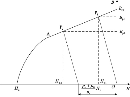
Dynamic operation point under eddy current magnetic field.
Damping force vs. velocity.
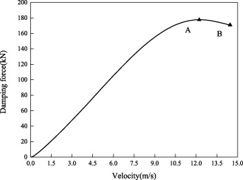
As we know from the analysis in Chapter 2 and 3, the damping process commences once demagnetization begins. When the structure of EMB remains unchanged, the impulse of intensive impact load will affect the curve of the eddy current damping force. The damping force no longer increases when the intensive impact load reaches the threshold. The corresponding relationship between the velocity and the damping force is shown in Fig. 17. It can be seen that there is a linearly increasing segment in the damping force curve, and the damping coefficient is close to a constant.
When the EMB reaches the threshold, which is the critical velocity, the peak of the damping force appears at point A, as illustrated in Fig. 17. The continuous increase of demagnetization causes the damping force to decrease gradually after point A. The maximum velocity and its damping force (F 2) occur at the end of the impact load, corresponding to point B in Fig. 17.
The critical velocity is an extremely important technical index of EMBs, especially under intensive impact loads. In the case of unreasonable design parameters, the maximum velocity will greatly exceed the critical velocity, resulting in insufficient damping and even accidents. The damping force is a function of velocity. Obviously, the damping force varies with the velocity. Therefore, based on the above analysis, the critical velocity is defined as:
Since the EMB studied has a thin-walled long tube structure, the skin depth is far greater than the tube thickness. Therefore, the skin effect is ignored in solving the critical velocity. The critical velocity is obtained as
The velocity at the peak of the damping force obtained by the intensive impact test is the critical velocity. The value of k m can be obtained by introducing the critical velocity of intensive impact test and structural parameters of EMB into Eq. ((21)). It should be noted that the critical velocity of the FE analysis is in good agreement with the intensive impact test, as shown in Table 2.
Critical velocity
This paper attempts to apply a cylindrical linear EMB to the field of intensive impact load. According to the characteristics of impact load, the time-step FE model is established. Combined with small-scale impact test and intensive impact test at room temperature, the damping and demagnetization mechanism is analysed systematically. The following conclusions are drawn:
(1) The small-scale impact test results show that the cylindrical linear EMB can effectively complete the damping process under the impact load with less energy. In this case, the damping coefficient remains basically unchanged.
(2) The intensive impact test results show that the demagnetization effect is existed in the entire buffering process. The demagnetization effect is obvious with the increase of velocity. When the demagnetization effect reaches a certain degree, the critical velocity is reached. The cylindrical linear EMB can also completely realize the attenuation process of intensive impact load with large energy.
(3) The magnetic Reynolds number obtained by the Ampere circuital theorem takes into full consideration the demagnetization effect of the magnetic field induced by eddy current on the original magnetic field. Compared with the existing models, the demagnetization process of EMB is more realistic by introducing the correction coefficient of magnetic Reynolds number k m.
However, it is worth noting that only eddy current demagnetization is studied in this paper. Taking high temperature demagnetization and permanent magnet self-demagnetization into account in the analysis model will cause the impact damping process to become more complicated. At the same time, the demagnetization effect of EMB under intensive impact load is simplified for convenience. For example, the magnetic field in the conductor tube is assumed as a uniform distribution, which cannot avoid causing some deviations. To establish a more accurate analysis model, further research is required to consider the unevenness of the eddy current. Moreover, the structural parameters optimization of EMB deserves a further study to obtain the ideal critical velocity and optimal damping force curve.
Footnotes
Acknowledgements
This work was supported by the China Postdoctoral Science Foundation (Grant No. BX2021126), the National Natural Science Foundation of China (Grant No. 301070603), and the Postgraduate Research & Practice Innovation Program of Jiangsu Province (Grant No. KYCX18_0383).