
Abstract
Precision machining fields require the worktable to have a large-scale multi-degree-of-freedom motion capability. In order to provide a more accurate magnetic model for the control strategy decoupling process and the size parameter optimization design process of the maglev rotary table. This paper proposes a new magnetic modeling method based on the Two-Dimensional Harmonic method. Different from the existing harmonic method, this method simultaneously considers the tangential and radial magnetic field changes of circumferential magnetic array. And it eliminates the edge effect of the magnetic flux density distribution in the radial aperiodic direction. The magnetic force and torque are solved by the Lorenz integral formula and the Gaussian quadrature method. In order to verify the accuracy of the TDH method, the boundary element software Radia TM is used for simulation, and a prototype is made for measurement. The experimental results shown that this method reduced the maximum error of the radial edge magnetic field from 104.19% to 3.29%. And it improved the calculation accuracy of magnetic force and torque by 60.74% and 84.39% respectively. This method does not rely on special example, and is beneficial to cross-platform applications. It is more suitable for realizing the magnetic modeling of the maglev rotary table with both rotational motion and large-stroke translational motion.
Keywords
Introduction
Traditional mechanical transmission methods limit the development of high-precision applications such as precision manufacturing and nano-scale positioning. The maglev system has the advantages [1,2] of no mechanical friction, simple structure, multi-degree-of-freedom (multi-dof) motion, and is generally regarded as a new solution. Scholars have proposed a large number of topological structures of maglev actuators to meet the application requirements in different working environments. They achieved good research results in multi-dof motion [3–6], high-precision positioning [3,7–9], micro-manipulation [10,11], rotary table [12–14] and tactile feedback system [11,15]. The maglev planar motor proposed in [1,2] realizes the multi-dof positioning of the system. The application of maglev technology in life sciences to achieve 3D micro-manipulation is mentioned in [10].
The micro-optical components have a 3D rotationally symmetric structure [16,17]. And its processing process [18,19] requires the worktable to realize the switching motion of multiple rotation axis. The processing size and structure of various micro-optical components are different, requiring the worktable to have the ability of large-stroke motion. The platforms used for the realization of both rotational motion and large-stroke translational motion mainly include maglev planar motor, a two-level linkage method, and maglev rotary table. In [2,20], the permanent magnet of the maglev planar motor is a non-rotationally symmetric structure, and the accuracy of the circular motion is lower than the accuracy of its translational motion. Two-level linkage [21,22] is achieved using the superposition of 1D linear mechanisms, and can only achieve 2-dof motion in the plane. It still belongs to the traditional transmission, and there are principle limits to its accuracy improvement. The circumferential magnetic array (CMA) of the maglev rotary table [12–14] has a closed-loop periodicity. It only needs to consider the phase problem when performing circular motion. The rotary table provides a good solution for precision-machined worktable.
The magnetic modeling methods of maglev systems mainly include finite element analysis method, numerical method based on magnetic charge, and harmonic method. Although the finite element method has high calculation accuracy, the calculation speed is slow. It is generally used for offline simulation [23,24] and cannot realize real-time control of the platform. Although the numerical method [25,26] can be used for real-time control, it does not obtain the analytical expression of the system model, and the calculation process requires expensive equipment such as FPGA. The harmonic method [12,14] can obtain the analytical expression of the magnetic field, and the calculation process is relatively simple. It has modeling advantage for platforms with periodic magnetic field distribution.
For the 1D halbach magnetic array [4,27] and CMA commonly used in maglev systems. The existing harmonic method only models the direction with periodic distribution characteristics, but ignores the actual distribution law in the aperiodic direction. Lu and Mark [12] used a PCB and CMA to form the maglev rotary table, which realized the z-axis rotational motion. However, the device restricts multi-dof motion, which is not conducive to the multi-scenario application. Lu et al. [14] proposed the use of radially placed coils and CMA to form the maglev rotary table. The existing harmonic method is also used to realize the z-axis rotational motion. However, only the upper long side region of the coil is used in modeling the system. The system consumes a large amount of power and the structure needs to be optimized. The application of the existing harmonic method to the special examples have become one of the factors restricting the platform to realize large-stroke motion due to the existence of model errors.
In order to meet the needs of precision machining fields [18,19,28] such as micro-optical components, the table should have both the ability of rotational motion and large-stroke translational motion. This paper uses coils and CMA to build the maglev rotary table system [13]. They all have a centrally symmetric structure, and the topological structure is shown in Fig. 1. The structure satisfies the requirements of a large-scale of multi-dof motion. It’s simple, and easy to manufacture and install. The system makes full use of the current regions of the coil to improve the driving force.

Topological structure of maglev rotary table.
In the modeling method, in order to solve the problem that the existing harmonic method has a large error in the solution of the magnetic field in the aperiodic direction. This paper proposes a two-dimensional harmonic (TDH) method, a magnetic modeling method for a maglev rotary table that comprehensively considers the radial pseudo-periodic Fourier model and the tangential periodic Fourier model. Different from the existing harmonic method which only considers the change of the magnetic field in a single direction, the TDH method accurately describes the actual distribution of the magnetic field in the spatial range, and solves the radial edge effect. We deduced a simple analytical expression of magnetic flux density, and used the Lorentz integral formula to complete the magnetic modeling of the maglev rotary table.
The rest of this paper is organized as follows. Section 2 defines the coordinate system and the magnetic field solution of the TDH method of the maglev rotary table. Coordinate transformations and magnetic modeling are given in section 3. Section 4 is about the experimental verification of the magnetic field solution and magnetic modeling results of the TDH method. Section 5 gives the conclusion of this paper.
The maglev rotary table device used in this paper for TDH model verification is shown in Fig. 1. It is composed of a rotor CMA and a backplane, stator coils and a basis. The rotor CMA consists of 48 permanent magnets distributed uniformly along a circle of radius R. The magnetization directions of the permanent magnets are vertical or tangential, and the arrangement order is marked in Fig. 2. The magnetization direction of every four adjacent permanent magnets is a period of repeated magnetization. And the CMA and the backplane are fixed to form the actuator of the maglev rotary table. The stator consists of 8 racetrack coils fixed on the basis. In order to reduce the iron loss caused by magnetic flux leakage or magnetic saturation. The backplane, basis and coil holder are made of aluminum alloy. The material of the permanent magnets is N48 grade of sintered NdFeB. The coils use copper wire.
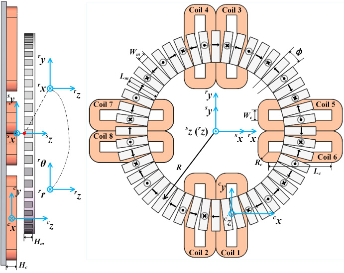
(a) Left view of maglev rotary table. (b) Top view of coils and circumferential magnetic array.
The current direction of each coil is counterclockwise in the top view of Fig. 2(b). The size parameters of the maglev rotary table and the constant values used in this paper are listed in Table 1.
The coordinate system is marked in Fig. 2. The definition of Cartesian coordinate system is: The origin
r
O of the dynamic coordinate system
The relative translation amount p = [
p
x
p
y
p
z]
T
of the maglev rotary table actuator is expressed by the coordinate of the origin
r
O in the coordinate system
Dimension parameter and constant value table
Dimension parameter and constant value table
In the modeling of the magnetic field, the existing harmonic method only solves the Fourier model according to the characteristics of the tangential periodic distribution of the CMA and obtains the magnetization vector function. It regards the permanent magnet as the ideal infinite length model in the radial direction, and ignores the radial distribution of the magnetic field. As a result, the magnetic field in the radial non-central region of CMA cannot be accurately solved.
The TDH method first uses the Fourier model to perform tangential periodic expansion and radial pseudo-periodic expansion of the CMA. The direction of the Fourier model is shown in Fig. 3. And the model is integrated to solve the magnetization vector function.
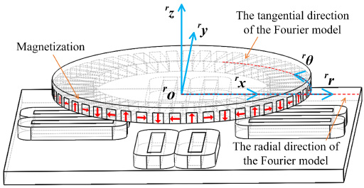
The direction of the Fourier model.
The actual length of the permanent magnet in the radial direction is L
m
. It is distributed in the shape of a single peak along the radial direction in the region of actual interest Δ, and the attenuation at both ends is zero. It is similar to the Fourier series method of solving single-period rectangular function in Cartesian coordinate system using pseudo-periodic concept. The distribution of the radial pseudo-periodic of the CMA is shown in Fig. 4. The radial Fourier model obtained by solving in the cylindrical coordinate system is:
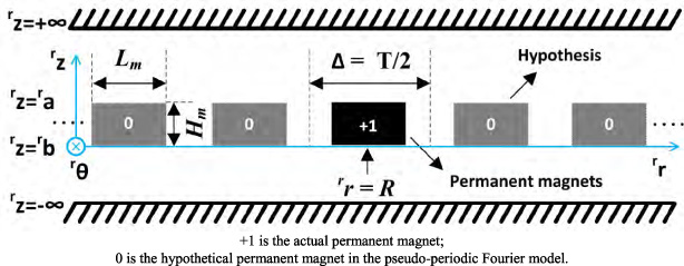
Distribution of radial pseudo-periodic permanent magnets.
The selection principle of the parameter-T of the radial pseudo-periodic Fourier model: suppose that the upper and lower bounds of the region of actual interest Δ are Δ
upper
and Δ
lower
, respectively. In a period around
r
r = R, the region
Then the Fourier model of tangential periodic distribution is solved, and the results are given in [14]. The distribution of tangential periodic CMA is shown in Fig. 5. The magnetization vector of the CMA can be obtained by combining the tangential and radial Fourier series, then the magnetization vector functions
r
M
θ and
r
M
z
of the TDH method are:

Distribution of tangential periodic magnetic array.
Where
In Maxwell’s theory [29], in this paper, the static magnetic field space generated by a CMA that does not conduct current can be expressed as:
The magnetic scalar potential method is used to solve the magnetic field equation. The spatial position of the CMA divides the z-axis direction of the dynamic coordinate system
According to the boundary value relationships of the magnetic field strength and magnetic flux density between adjacent regions, and the limit condition that the magnetic scalar potential is zero at infinity. Using the method of variable separation, the expression of the magnetic scalar potential in the air region 3 where the coil is located is:
Finally, the Maxwell equation is used to solve the formula for the magnetic flux density. We got the expression of target region 3:
Therefore, the analytical expression of the spatial magnetic field strength of the CMA is obtained through the above process. It is expressed in Cartesian coordinate system through coordinate transformation, which provides accurate magnetic flux density calculation for the magnetic modeling process of the maglev rotary table.
Next, we take the coil 1 and the CMA as examples for magnetic modeling. For a particular coil 1, the coordinate of the origin
c
O of

Marking diagram of each region of coil 1.
Section 2.1 introduced the definition of each coordinate system used in magnetic modeling. The calculation of the magnetic flux density and the calculation of the coil nodes and the magnetic force are performed in different coordinate systems. Therefore, we need to first transform each coil node to the dynamic coordinate system
(1) Transform the coil nodes represented under the coordinate system
If the coil node in
Substituting the coil node expressed in the cylindrical coordinate system
Now the Lorentz integral formula is used to solve the magnetic force and torque experienced by the actuator. The 4th order Gaussian quadrature [28] is used for numerical calculation.
According to the geometrical characteristics of the coil, it is divided into eight regions as shown in Fig. 6. The variable n = 1–8 is used to represent each region. In the rectangular and fan-shaped regions, the solution of the coil nodes, current density, magnetic force and torque is slightly different.
(1) Rectangular region
According to the Gaussian quadrature, the coil node and current density of the rectangular region are:
(2) Fan-shaped region
The magnetic force and torque generated by the current of each region of a single coil can be calculated by (13)–(14), (17)–(18). Similarly, the magnetic force and torque generated by other coils can be obtained. Then express them in the fixed coordinate system
Thus, the magnetic modeling of the maglev rotary table is realized. The magnetic model establishes the relationship between the control quantities for the real-time control of the maglev rotary table.
In order to verify the magnetic flux density distribution and magnetic model of the maglev rotary table proposed in this paper. We use the maglev rotary table and a 6-DOF load cell (ATI mini40) to form the experimental device, as shown in Fig. 7. The measurements and the simulation results of the boundary element software Radia TM are used as reference standards. The magnetic field and magnetic force calculation results of the TDH method are verified and compared with the results of the existing harmonic method.
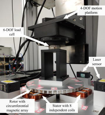
Maglev rotary table experimental device.
The magnetic field of the CMA has a good periodicity along the tangential direction. The calculation results of the existing harmonic (EH) method [14] in the radial central region of the permanent magnet perform well. Similar to the experimental setup in most literatures, the arc of
r
r = R,
r
z = −1 mm,
r
θ ∈ [0°, 90°] in the cylindrical coordinate system
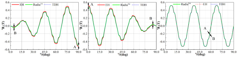
Magnetic flux density distribution when r r = R, r z = −1 mm obtained via different methods.
The error of the experimental data in this paper is expressed by the relative error between the calculation result of each method and the Radia
TM
result. The formula is
Experimental data shows that the maximum error of the existing harmonic method magnetic field calculation in this region is 5.49%, and the TDH method has achieved better results, the maximum error is 4.07%. It can be seen that in the region where the existing harmonic method performs best (Compared with the accuracy of other regions), the TDH method solution accuracy is further improved. When the rotation range of the z-axis is large, the TDH method can meet the magnetic field solving requirements of the maglev rotary table. Although the existing harmonic method relies on the radial center point of the permanent magnet, some good results have been achieved in this region. Through simulation analysis, its calculation accuracy will decrease as the radial length L m of the permanent magnet decreases. The performance of the TDH method is less affected by L m , and the radial length change will hardly affect its calculation accuracy.
When realizing the translational motion of the maglev rotary table in the horizontal plane, the magnetic field in other regions of the CMA also have a great influence on the calculation of force and torque.
We continue to verify the effectiveness of the TDH method in solving the magnetic field in the radial edge region of the CMA. Similar to the first experiment, the edge arc region

Magnetic flux density distribution when
r
r = R +
The TDH method takes into account the characteristic that the CMA has a finite length distribution along the radial direction. Next, we select two regions that change in the radial direction for experimental verification. Fig. 10. shows the results of solving the magnetic flux density in the regions of
r
θ = 0 rad,
r
z = −1 mm,
r
r ∈ [40 mm, 120 mm] and
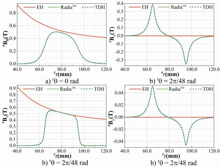
Magnetic flux density distribution in the radial region. (a) When
r
θ = 0 rad. (b) When
r
θ =
The magnetic flux density in other directions is zero in r θ = 0 rad, so it is not shown. The illustrated results show that the TDH method also has a very good calculation accuracy performance in the regions that changes in the radial direction, and the data tracking effect is good. However, the existing harmonic method can hardly be calculated in this region and it cannot meet the calculation requirements in translational motion.
Further, we discuss the effect of parameter changes on the accuracy of the TDH method and the existing harmonic method through a series of experiments. The datum of parameters and coordinates are: L m = 30 mm, R = 80 mm, T = 600 mm, and [ r r, r θ, r z] = [R + 15 mm, r θ, −6 mm], r θ ∈ [0°, 90°]. The parameters involved include L m , R, and T, and the comparison process is realized by changing their values one by one. The data is shown in Fig. 11. From the analysis of the experimental results, the calculation effect of the existing harmonic method is greatly affected by L m . Although the calculation accuracy can be improved by increasing the value of L m , satisfactory results have not been obtained in all regions. The calculation accuracy of the TDH method has a small relationship with the values of L m and T, and has always maintained a good performance. The effect of the parameter R on the results of both methods can be ignored. To sum up the experimental conclusion, the high-precision performance of the TDH method calculation results is hardly affected by the change of the dimensional parameters. The model is not limited to specific examples and has good portability.

Model accuracy with different parameters. (a) Change the parameter L m . (b) Change the parameter R. (c) Change the parameter T.
(1) Magnetic force and torque generated when coil 1 works
In the discussion of Section 3, taking the coil 1 as an example, the magnetic modeling process of the maglev rotary table was given. When only the coil 1 supplies the driving current, the magnetic rotary table performs the rotational motion of p = [0 0 1] T mm, 𝛾 ∈ [0°, 60°] and the diagonal translational motion p from [−29 −29 1] T mm to [20 20 1] T mm. The results were verified separately, based on the measurements and Radia TM simulation results, and compared with the existing harmonic method. The current density of coil 1 is set to 1 A/mm2, and the experimental data is shown in Fig. 12(a) and (b).
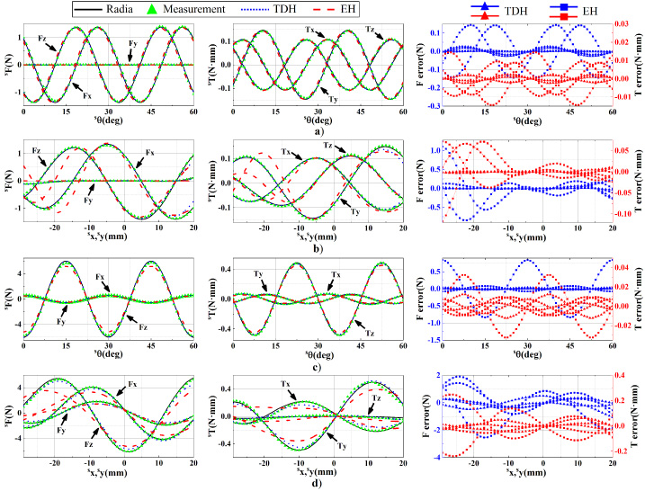
The distribution of magnetic force and torque obtained via different methods. (a) Rotational motion with coil 1 only. (b) Translational motion with coil 1 only. (c) Rotational motion for all coils work. (d) Translational motion for all coils work.
It can be seen from the figure that the modeling results of the TDH method are more consistent with the real data. According to the calculation results of magnetic force and torque in the rotational motion, the maximum error of the existing harmonic method is 10.45% and 9.77%, the maximum error of the TDH method is 1.94% and 1.82%, and the accuracy is improved by 8.51% and 7.95%, respectively. This contrast is more pronounced in translational motion, and the existing harmonic method performs poorly. According to the calculation results of magnetic force and torque, the maximum error of the existing harmonic method reaches 78.56% and 78.91%, whereas the maximum error of the TDH method is only 17.82% and 16.10%. Compared with the existing harmonic method, the calculation accuracy of the TDH method is improved by 60.74% and 62.81% respectively.
(2) Magnetic and torque verification of maglev rotary table
The calculation process of the magnetic force and torque generated by other coils in the maglev rotary table is the same as the method of the coil 1 introduced. Only the location
In the experiments, the current of each coil is set to [0.4 −0.3 −0.4 0.3 0.2 −0.1 −0.2 0.1] T A. We let the actuator perform the rotational motion p = [0 0 1]T mm, 𝛾 ∈ [0°, 60°]. The magnetic force and torque data of 60 points collected at equal intervals in the region are plotted in Fig. 12(c), and the calculation results are compared with the existing harmonic method. When the maglev rotary table works as a whole, the magnetic force received by the actuator is relatively large. The 6-DOF load cell has some deviations from the ideal position at each sampling point. The position deviation causes some errors between the measurements and the real data. The experimental results show that the TDH method have achieved more accurate results compared to the existing harmonic method. The TDH method reduces the maximum error of magnetic force and torque calculation from 13.91% and 14.82% to 1.02% and 11.40%, respectively.
In the translational motion experiment of the maglev rotary table, we let the actuator perform the diagonal motion p from [−29 −29 1] T mm to [20 20 1] T mm. The experimental data is shown in Fig. 12(d). Through data analysis, the TDH method calculation results avoid the failure phenomenon of the existing harmonic method, and maintain good accuracy and trend tracking ability. The TDH method reduces the maximum error of magnetic force and torque calculation by 57.88% and 84.39%, respectively. Therefore, the TDH method is more suitable for the magnetic modeling of the maglev rotary table, and realizes the rotational motion and large-stroke translational motion capability of the rotary table.
In the field of precision machining which requires multiple rotation axis switching, the maglev rotary table is a preferred platform for achieving rotational motion. In order to achieve the ability of both rotational motion and large-stroke translational motion, and to provide an accurate magnetic model for the optimal design of the maglev rotary table, this paper proposes a new magnetic modeling method for maglev rotary table. The TDH method deduces the analytical expression of the calculation of the spatial magnetic flux density of the CMA, which has a higher accuracy in solving the magnetic field than the existing harmonic method. By integrating the radial and tangential Fourier models, the actual distribution characteristics of the CMA are accurately described, and the edge effect of the radial magnetic field is solved. We use the Lorentz integral formula and Gaussian quadrature to calculate the magnetic force and torque of the maglev rotary table. The experimental results show that the TDH method has good performance in the static test of the rotational and translational motion of the maglev turntable.
The proposed method overcomes the weakness of the existing harmonic method which only considers the driving force of the long side region of the coil. The solution range of this method is wider, and the driving force of the entire coil to the actuator is accurately considered in the numerical calculation. The TDH method provides an accurate magnetic model for the optimal design of the maglev rotary table and for the decoupling process of the control algorithm in the multi-dof motion. The calculation accuracy of the TDH method doesn’t depend on the dimensional parameters of specific examples. It has good portability and is conducive to cross-platform applications. The TDH method provides an accurate magnetic model for the maglev rotary table to achieve unlimited rotational motion and large-stroke translational motion at the same time, which is conducive to exerting the best performance of the platform and expanding the industrial application scenarios of the platform. Further research on the excellent motion control algorithm of maglev rotary table will be the focus of our next work.
Footnotes
Acknowledgements
This work was funded by the National Natural Science Foundation of China under Grant 51705375 and 51975422, Applied Research on Advanced Technology of Wuhan under Grant 2018010401011284.