
Abstract
In order to solve the problem of short service life (2 months) and zero leakage of air cylinder in aerospace engineering, this paper innovatively designs a magnetic fluid sealing device of air cylinder in aerospace engineering through magnetic circuit analysis and magnetic fluid sealing theory. The magnetic field finite element method is used to calculate the magnetic field distribution in the sealing gap under different key parameters such as the number of pole teeth, the height of the radial sealing gap, the thickness of the permanent magnet, the slot width, the ratio of pole piece height to shaft. And numerical analysis of the number of pole teeth, the radial sealing gap height, permanent magnet thickness, slot width, the ratio of pole piece height to shaft and other key parameters on the magnetic fluid sealing performance. Finally, the reliability of the reciprocating magnetic fluid sealing withstand voltage is verified by experimental methods. Research indicates. The pressure capabilities of magnetic fluid sealing is increasing with the increase of the number of pole teeth. The pressure capabilities of magnetic fluid sealing is decreasing with the increase of the radial sealing gap. The sealing withstand voltage increases first and then decreases with the increase of the thickness of the permanent magnet, and finally increases, and the value of the withstand voltage is the largest when the thickness of the permanent magnet is 7.8 mm. The sealing pressure capabilities increases as the slot width increases. The sealing withstand voltage increases first and then decreases as the ratio of pole piece height to shaft increases, and when the ratio of pole piece height to shaft is 0.8, the sealing withstand voltage reaches a maximum value. The pressure test finally reaches the pressure value of 6 MPa, which can meet the pressure value demand of medium pressure cylinder, indicating that the magnetic fluid sealing technology can effectively solve the leakage problem existing in the air cylinder technology of Aerospace Engineering, and improve the reliability and service life of the air cylinder.
Keywords
Introduction
Magnetic fluid has a wide range of applications and significance in dust prevention, leakage prevention, sealing and other fields. The application of magnetic fluid sealing in the air cylinder of aerospace engineering is an innovation [1]. Magnetic fluid is injected into the sealing gap between the pole teeth and the reciprocating shaft, which can be stabilized in the sealing gap under the action of magnetic field, forming a special “O” type sealing ring to prevent the mutual leakage of gas and dust in the internal and external environment. Magnetic fluid sealing technology is a new type of sealing technology composed of special materials science, electrothermal science and other interdisciplinary subjects [2]. Compared with the traditional rubber ring sealing technology, it has obvious advantages such as zero leakage, no friction, low power consumption, high sealing performance and so on, which can satisfy the requirements of high pressure and high efficiency of reciprocating air cylinder [3]. Combined with the theory and method of modern electromagnetics, the magnetic fluid sealing technology is applied to solve the sealing problem of air cylinder in aerospace engineering, which is of great significance to improve the performance of reciprocating air cylinder and effectively solve the sealing problem in aerospace engineering [4].
Magnetic circuit design of magnetic fluid sealing
According to magnetohydrodynamic analysis, the internal pressure formula is:
The circuit and the magnetic circuit in the sealing structure are basically the same. The current value I in circuit science is equivalent to the magnetic flux Φ in the sealing structure magnetic circuit. The electromotive force E in circuit science provides the power equivalent to the magnetomotive force NI provides the magnetic source in the sealing structure. The capabilities in circuit is equivalent to the R in magnetic circuit, The conductivity σ in the circuit is equivalent to the permeability μ in the magnetic circuit structure [5–7]. Similar to circuit science discipline, the circuit structure must be a closed electrical circuit. Similarly, for the magnetic circuit, the magnetic flux should also be a completely closed circuit. As the pole piece contains two structures, the pole piece itself and the pole tooth, with different shapes and sizes, the pole piece and the pole tooth are specially considered as two parts, which are respectively represented by the magnetic capabilitiess R p and R t . This simplified structure contains several assumptions: A. ignore the influence of magnetic leakage in the structure; B. ignore the edge effect in the corresponding structure. The theoretical magnetic circuit diagram of the sealing structure can be simplified as Fig. 1. F m is the magnetic potential of the permanent magnet; R m is the permanent magnet reluctance; R p is the pole piece reluctance; R t is the pole tooth reluctance; R g is the sealing gap reluctance; R a is the shaft reluctance.
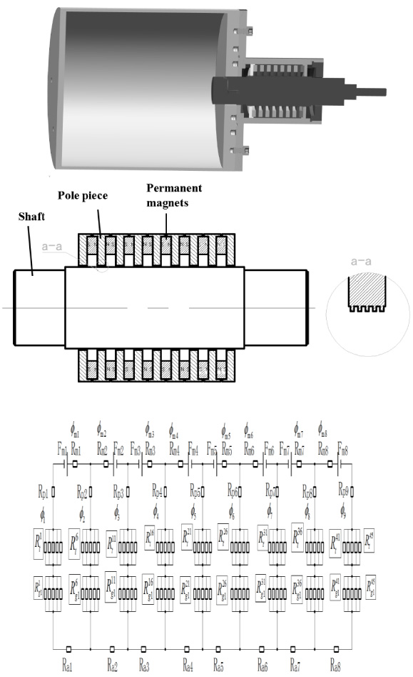
Magnetic circuit diagram of multi-stage seal with magnetic fluid seal structure.
The design process of magnetic circuit is as follows:
According to Kirchhoff’s first law of magnetic circuit:
From formulas (5) and (6), obtain that:
From
R
p2,
Effect of the number of pole teeth on the pressure capabilities
The number of pole teeth will directly affect the magnetic field gradient and magnetic flux in the sealing gap of the air cylinder, which will directly affect the sealing pressure capabilities. Taking the width of the pole piece as a fixed value, the reasonable design of the number of pole teeth is of great significance to improve the pressure capabilities of sealing device. The finite element method is used to calculate the magnetic field distribution in the sealing gap, and the number of pole teeth is 1 ∼ 5. The magnetic field distribution is shown in Fig. 2.
Magnetic field distribution under different number of pole teeth.
According to the numerical simulation results, the corresponding total magnetic flux is calculated as shown in Table 1, and the relationship between the pressure capabilities (ΔP) of the magnetic fluid sealing of the air cylinder and the number of pole teeth can be calculated as shown in Fig. 3.
Total magnetic flux under different number of pole teeth
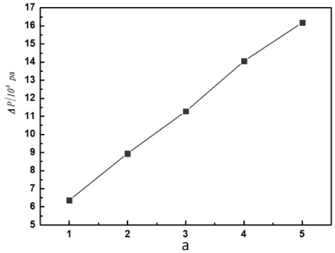
Effect of the number of pole teeth on the pressure capabilities.
The sealing pressure capabilities increases linearly with the number of pole teeth. Since the axial distance of the pole piece in the same sealing structure is constant, when the number of pole teeth increases, the relative reluctance in the sealing gap decreases, and the permeability increases. The magnetic flux in the whole structure increases with the number of pole teeth. According to the magnetic circuit analysis, the number of teeth increases obviously, and the magnetic capabilities of the whole structure decreases. When the number of teeth is 5, the theoretical magnetic capabilities is the smallest and the magnetic flux of the magnetic circuit is the largest. Therefore, under limited processing conditions and sealed space, try to set the number of pole teeth to 5.
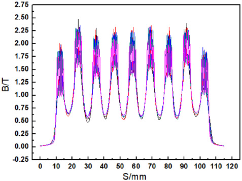
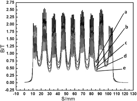
The effect of the radial sealing gap between the polar teeth and the reciprocating shaft on the pressure capabilities of the magnetic fluid sealing is shown in Fig. 4. With the increase of radial sealing gap from 0.1 mm to 0.5 mm, the maximum flux density in the sealing gap decreases gradually, and the sealing pressure capabilities decreases correspondingly. a, b, c, d and e respectively represent the sealing gap of 0.1 mm, 0.2 mm, 0.3 mm, 0.4 mm and 0.5 mm.
Magnetic field distribution under different sealing gap.
As can be seen from Fig. 4 that when the radial sealing gap is 0.1 mm, the magnetic flux in the sealing gap formed by a single pole tooth and a shaft is the largest, which indicates that the pole tooth is an important parameter affecting the sealing pressure capabilities. When the radial sealing gap is greater than 0.4 mm, the magnetic field intensity under the sealing pole teeth is no longer so uniform, and the magnetic flux under a single pole tooth is also not obvious. The magnetic flux is calculated according to the withstand voltage formula, and the calculation results are shown in Table 2. Magnetic fluid are selected as oil based magnetic fluid and its saturation magnetization is 41.6 kA/m. The sealing pressure capabilities can be calculated in Fig. 5.
Total magnetic flux under different sealing gap

Effect of the sealing gap on the pressure capabilities.
The sealing gap greatly affects the sealing pressure capabilities, The pole piece at both ends of the sealing structure are supplied by a single permanent magnet, and the middle pole piece are supplied by two permanent magnets. It can be seen from Fig. 5 that the sealing pressure capabilities decreases with the increase of radial sealing gap. This is because when most parameters of the sealing structure remain unchanged, the radial sealing gap increases, the magnetic capabilities of the sealing gap increases, the magnetic flux density in the sealing gap decreases, and the magnetic induction intensity under a single pole tooth also decreases, which leads to the decrease of the pressure capabilities of the magnetic fluid sealing.
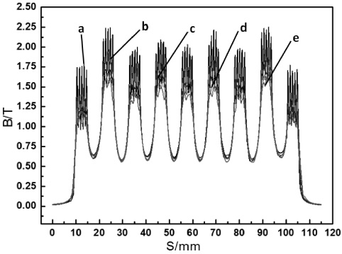
The thickness of the permanent magnet affects the axial length of the whole sealing structure. The axial thickness of the permanent magnet should be minimized on the premise of meeting the required magnetic flux. The finite element method is used to calculate the magnetic field distribution in the thickness of the permanent magnet. The effect of the thickness of the permanent magnet between the polar teeth and the reciprocating shaft on the pressure capabilities of the magnetic fluid sealing is shown in Fig. 6a, b, c, d and e respectively represent the the axial length of permanent magnet is 5.8 mm, 6.3 mm, 6.8 mm, 7.3 mm and 7.8 mm.
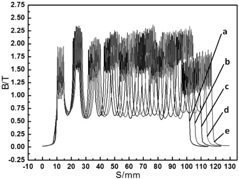
Magnetic field distribution under different thickness of the permanent magnet.
It can be seen from Fig. 6 that when the thickness of permanent magnet increases to 7.8 mm, the magnetic flux under the pole teeth in the first pole piece on the right increases rapidly. The flux curves of different permanent magnets under the first pole piece on the left side under different parameters basically coincide, and the change of high and low magnetic induction intensity on the pole teeth is not obvious, but the corresponding axial position is changed. According to the theory of magnetic fluid sealing and the magnetic field distribution in the radial sealing gap under the different thickness of permanent magnet in Fig. 6. According to the numerical simulation results, the corresponding total magnetic flux is calculated as shown in Table 3, and the relationship between the pressure capabilities (ΔP) of the magnetic fluid sealing of the air cylinder and the thickness of permanent magnet can be calculated as shown in Fig. 7.
Total magnetic flux under different thickness of permanent magnet
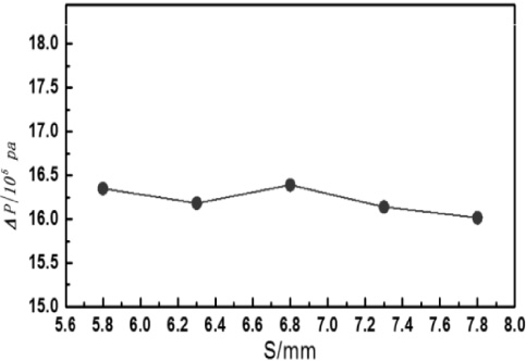
Effect of the thickness of permanent magnet on the pressure capabilities.
The pressure capabilities of the magnetic fluid seal is basically unchanged with the increase of the thickness of the permanent magnet. The reason is that the best working position of the model is approximately at the position with the thickness of the permanent magnet of 5.8 mm, so when the thickness of a single permanent magnet increases, the working point of the magnetic field provided by the permanent magnet is very close to the remanence point, and the working state is close to saturation, which only makes little contribution to the increase of the magnetic flux of the magnetic circuit, and the sealing capacity of the device is basically stable. Therefore, choosing the appropriate thickness of the permanent magnet can not only reduce the axial length of the sealing structure and the required sealing space size, but also improve the utilization rate of the permanent magnet materials and save the production cost of the whole sealing structure.
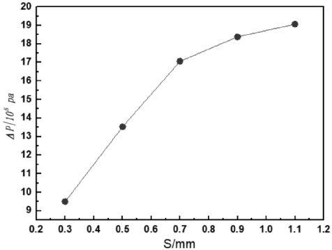
The slot width is an important key parameter affecting the pressure resistance of the sealing. In the analysis, it is necessary to keep other parameters unified and increase the slot width, but without changing the width of the pole tooth, the overall thickness of the pole piece will be increased. The effect of the thickness of the slot width between the polar teeth and the reciprocating shaft on the pressure capabilities of the magnetic fluid sealing is shown in Fig. 8a, b, c, d and e respectively represent the slot width is 0.3 mm, 0.5 mm, 0.7 mm, 0.9 mm and 1.1 mm.
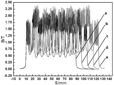
Magnetic field distribution under different slot width.
It is not difficult to find that when the slot width increases from 0.3 mm to 1.1 mm, the maximum magnetic flux is increasing, and the gradient change of magnetic induction intensity under a single pole tooth is more obvious; when the slot width is 1.1 mm, the gradient change of magnetic induction intensity under a single pole tooth is the most significant, and the total and maximum magnetic induction intensity at this time. According to the numerical simulation results, the corresponding total magnetic flux is calculated as shown in Table 4, and the relationship between the pressure capabilities (ΔP) of the magnetic fluid sealing of the air cylinder and the slot width of permanent magnet can be calculated as shown in Fig. 9.
Total magnetic flux under different slot width
Effect of the slot width on the pressure capabilities.
Magnetic field distribution under different ratio of pole piece height to shaft.
With the increase of the slot width, the sealing pressure resistance capacity is increasing. Because the saturation magnetization of permanent magnet is relatively high, it can meet the magnetic energy requirements in the magnetic circuit. When the slot width increases, the minimum magnetic field strength between teeth becomes clear. The main influence of the slot width is the minimum magnetic flux value B min. When the slot width decreases, the minimum magnetic flux under the slot is the minimum When the value of B min increases, the single-stage total flux ΔB = B max − B min decreases.
Total magnetic flux under different ratio of pole piece height to shaft
Effect of ratio of pole piece height to shaft on the pressure capabilities.
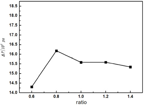
When the radial sealing gap is kept at 0.1 mm, the height of pole piece is changed without changing the shaft radius of 25 mm, and the outer radius of pole piece is respectively 20 mm, 25 mm, 30 mm, 35 mm and 40 mm. The effect of the ratio of pole piece height to shaft between the polar teeth and the reciprocating shaft on the pressure capabilities of the magnetic fluid sealing is shown in Fig. 10a, b, c, d and e respectively represent the ratio of pole piece height to shaft is 0.6, 0.8, 1, 1.2 and 1.4.
Overall physical object of the experimental platform.
When the ratio of pole piece height to shaft changes, the maximum and minimum flux B is changing, and the overall trend is that the maximum flux B gradually decreases. According to the numerical simulation results, the corresponding total magnetic flux is calculated as shown in Table 5, and the relationship between the pressure capabilities (ΔP) of the magnetic fluid sealing of the air cylinder and the ratio of pole piece height to shaft of permanent magnet can be calculated as shown in Fig. 11.
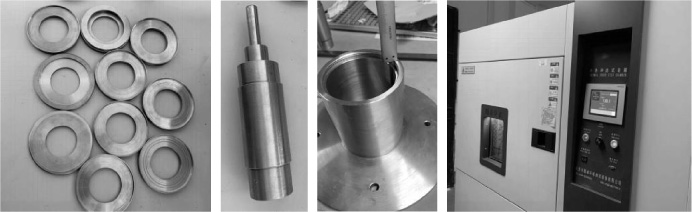
Sealing parts and high and low temperature test chamber.
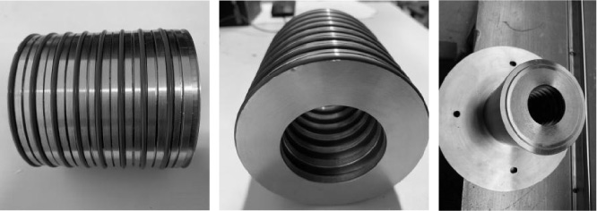
Assembly sealing components.

Pressure value of sealing test.
The sealing withstand voltage increases first and then decreases as the ratio of pole piece height to shaft increases, and when the ratio of pole piece height to shaft is 0.8, the sealing withstand voltage reaches a maximum value. When the ratio of the pole piece height to shaft increases from 0.6 to 0.8, the pressure capabilities of magnetic fluid sealing of the air cylinder increases by 0.1 and 0.2 atmospheres. This is because the increase of the ratio of pole piece height to shaft makes the magnetic field utilization in a certain effective range. When the ratio is 0.8, the utilization is the best, and the increase of the magnetic flux can effectively increase the sealing pressure resistance. Therefore, in order to obtain a magnetic fluid sealing device with high cost performance, the reasonable ratio of the pole piece height to shaft is 0.8.
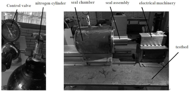
The sealing test bench is shown in Fig. 12. The experimental platform consists of electrical machinery, seal chamber, sealing component, pressure gauge, connecting pipeline, pressure control valve and nitrogen cylinder. Sealing parts and high and low temperature test box as shown in Fig. 13, assembly sealing components as shown in Fig. 14.
The whole experimental process is to test the static sealing pressure value, and adjust the pressure in the sealing chamber from 0 to 6 Mpa. The value added in each experiment is 0.5 MPa, gradually pressurized to 6 Mpa, as shown in Fig. 15 [12–14].
In this section, the test bed of magnetic fluid static sealing is designed, the corresponding sealing components are processed, the corresponding sealing test bed is built, the static sealing pressure test and pressure maintaining test of magnetic fluid static sealing seal are carried out, the pressure in the sealing chamber is continuously pressurized to 6 Mpa, which indicates that the pressure maintaining capacity of the static seal reaches 6 Mpa, The experimental results can meet the technical requirements of medium pressure cylinder seal, which shows the success of the whole test [15].
Conclusion
The pressure capabilities of magnetic fluid sealing is increasing with the increase of the number of pole teeth; The pressure capabilities of magnetic fluid sealing is decreasing with the increase of the radial sealing gap; The sealing withstand voltage increases first and then decreases with the increase of the thickness of the permanent magnet, and finally increases, and the value of the withstand voltage is the largest when the thickness of the permanent magnet is 7.8 mm; The sealing pressure capabilities increases as the slot width increases; The sealing withstand voltage increases first and then decreases as the ratio of pole piece height to shaft increases, and when the ratio of pole piece height to shaft is 0.8, the sealing withstand voltage reaches a maximum value. The pressure test finally reaches the pressure value of 6 MPa, which can meet the pressure value demand of medium pressure cylinder, indicating that the magnetic fluid sealing technology can effectively solve the leakage problem existing in the air cylinder technology of Aerospace Engineering, and improve the reliability and service life of the air cylinder.
Footnotes
Acknowledgements
The authors gratefully acknowledge the support of the National Natural Science Foundation of China (Grant No. 61773265 and 51675264), the support of grants from the Civil Aerospace Research Project of China. The support of Manned Space Advance Research Project (Grant No. 030601) and Civil Aerospace Technology Advance Research Project (Grant No. D030103).
Data availability
Some or all data, models, or code that support the findings of this study are available from the corresponding author upon reasonable request.