
Abstract
The disc coreless permanent magnet synchronous machine (PMSM) has a special coreless structure. This kind of PMSM has very low inductance, which is referred to as the low-inductance PMSM(LIPMSM) in this paper. The LIPMSM offers many advantages to drive systems. However, the current fluctuates strongly when driven by general converters, which makes the LIPMSM difficult to be popularized into modern drive systems. To tackle the above problems, a converter with output inductance is used. The influences of the inductance on the performance of the LIPMSM system are analysed, including current fluctuations, the maximum speed without flux weakening and the current response time. Based on above analyses, a method of obtaining the optimal inductance is proposed to obtain the optimal inductance simply and efficiently. The method has been verified through simulations and experiments. The system cannot work due to the huge current fluctuations when driven by the general converter. By using the converter with the optimal inductance, the current fluctuations have been reduced to 2 A. The experimental LIPMSM can reach 11000 rpm with very short response time of the current. Therefore, the LIPMSM system performance can been improved significantly and meet the requirements by using the converter with the optimal inductance.
Keywords
Introduction
The disc coreless permanent magnet synchronous machine (DCPMSM) has attracted much attention over recent years. The DCPMSM offers many advantages in modern driven systems, such as high power density, high efficiency, short axial size, strong overload capacity and fast response times [1,2]. The DCPMSM is suitable for lightweight or short axial mounting dimension applications. It can be used as the wheel hub motor, the robot arm motor, unmanned aerial vehicle motor, and etc. Since the stator is designed to be of a coreless structure, the armature reaction is weak. The magnetic circuit is hard to saturate, which makes the motor parameters generally consistent whatever the current of the motor is. The control algorithm can be simplified due to this advantage. And the motor system would work more efficiently [3,4]. The stator inductance (generally no more than 100 μH) [5,6] of the DCPMSM is far less than that of the ordinary permanent magnet synchronous machine (PMSM) which includes a core structure. In this paper, this kind of PMSM that has low stator inductance is referred to as the low-inductance PMSM (LIPMSM).
General converters mostly use the two-level voltage source inverters (VSI), which adopt the seven-segment algorithm as their modulation algorithm. The output voltage is adjusted by utilizing pulse width modulation (PWM). Thus, the motor current and torque can be controlled indirectly by controlling the output voltage [7,8]. However, the PWM is based on the impulse equivalent principle. It means that in each control cycle, if the impulse of a continuous input and a discrete input are equal, the control effects produced from each will be the same when driving an inertial object. The inductance is a significant component to the inertia of the motor system, which is the precondition of the impulse equivalent principle and the PWM.
The switching frequency of IGBTs is generally around 10 kHz, and its maximal switching frequency is no more than 20 kHz [9,10]. Most general converters use IGBTs as their switching devices. However, these devices maximum switching frequency is not high enough to meet the requirements of the LIPMSM, which makes the LIPMSM difficult to work well in drive systems. The most serious problem of the LIPMSM drive system is that the current fluctuations can be very large [11–13]. The LIPMSM is driven by several vectors generated by the converter at each period. The current will increase rapidly when forced by the active vectors. Such a rapid rise in current could cause the controller to trip on protection mechanisms, which would halt the operation of the motor temporarily, and even cause damage to the converter. On the contrary, the current could decrease rapidly when forced by a zero vector, which could even cause the current to become discontinuous [14,15]. Therefore, the general converter is not suitable for LIPMSMs. The large current fluctuations are the major drawback in utilising this motor in driving applications.
Much research has been conducted investigating the use of LIPMSM in driving applications. The current fluctuations can be reduced by increasing the switching frequency of the converter [11,16,17]. The equivalent effect of the PWM will be better when the switching frequency is increased. And therefore, the performance of the motor system will be improved. In [16], the current fluctuations had been greatly reduced by increasing the switching frequency of the converter to 100 kHz. The MOSFETs being selected to achieve such high switching frequencies. The three-level converter is utilized to reduce the voltage stress across each MOSFET, whose breakdown voltage would not be sufficient in two-level configurations. Although the current fluctuations are reduced, the converter configuration and the control algorithm used in [16] are much more complex than general approaches. And the performance can be deteriorated if the neutral-point voltage is changed, which is the inherent shortcoming of the three-level converter. However, for the same switching frequency, the performance of the LIPMSM is always poorer than that of the ordinary PMSM [17]. Thus, the LIPMSM must be operated at higher switching frequencies to have the same performance of the PMSM. With the increase of frequency, switching losses become far more considerable, and the electromagnetic compatibility problems become very serious. The performance of the motor system is diminished due to the too-high switching frequency. Therefore, it is difficult to achieve satisfactory performance by increasing the switching frequency alone.
The degree of modulation for the inverter can be increased by adjusting the bus voltage. This method can reduce the harmonics of the inverter output voltage, which is conducive to reducing the current fluctuations [18,19]. In [20], the bus voltage is adjusted in real time to make the difference between the bus voltage and the back electromotive force (back EMF) be maintained within a certain range. However, a new structure of the bus circuit is required. It consists of lots of independent DC sources that are difficult to be acquired and implemented. And the improvement effect is generally not significant. To further improve the performance of the LIPMSM, the bus voltage is changed in real time and the switching frequency is increased greatly up to 200 kHz in [21]. However, the ordinary IGBTs can’t achieve such a high switching frequency. Therefore, the method proposed in [21] is not suitable for the general converter.
The impulse equivalence principle can be met better when the inductance of the system is increased. The performance of the motor system is then improved [22,23]. In [22] and [23], an inductor is added to the bus circuit of the converter, which can intrinsically increase the inductance of the motor system directly. The current is controlled by the chopper of the current source. The current fluctuations can be reduced by controlling the bus current directly. However, the system reliability is compromised greatly because this method is chopping the current source. And vibrational noise can be induced due to the resultant square-wave currents.
For the aforementioned methods, there are large changes between the general and aforementioned converter configurations. These changes include improving the bus circuit, the inverter circuit or utilizing high-switching-frequency power switching devices. And the control algorithms of the aforementioned methods are more complex and with greater difficulty in implementation by using the general converter. All these factors make the LIPMSM difficult to popularize in modern motor drive systems.
In order to improve the performance of the LIPMSM system and implement simply in the general converter, a converter with output inductance is adopted to increase the intrinsic inductance of the LIPMSM system. This method can make the LIPMSM drive well by using the general hardware structure and control algorithm of the general converter. It is very easy to implement over other proposed approaches, which is conducive to the popularization of LIPMSM in the field of motor drive systems. The influences of the inductance on the performance of the motor system are analysed in this paper, which include the influences on the current fluctuations, the maximum speed without flux weakening and the current response time. To make the performance of the LIPMSM system meet the requirements, a method of obtaining the optimal inductance is proposed that is based on the above analyses. This method can also guide the design of the inductance of the motor. Simulation and experimental results verify that the optimal inductance can be obtained simply and efficiently by using the proposed method. The performance of the LIPMSM system is improve to meet the requirements by using the converter with the optimal output inductance.
Converter with output inductance
Design of converter with output inductance
The new converter is designed with output inductance as shown in Fig. 1. The three-phase inductor is added to the output side of the converter, which gives the effect of increasing the inductance of the whole system. If the inductance is proper, the performance of the system can be significantly improved.
In Fig. 1, the converter output inductance L s is shown inside the dashed box. L sA , L sB , and L sC are the output inductance of phase A, B, and C respectively. The rest of the loads are the motor equivalent circuit, where L m is the motor phase inductance. L mA , L mB , and L mC refer to the inductance of each subscripted phase. Likewise, R A , R B , and R C are the motor resistance of phases A, B, and C respectively. e A , e B , and e C are the back EMF of phases A, B, and C respectively. The total inductance L ms consists of L msA , L msB , and L msC , which is equal to the sum of the converter output inductance L s and the stator inductance L m , such that, L ms = L s + L m .
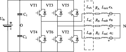
The topology of converter with output inductance.
According to the characteristics of the LIPMSM, it satisfies the conditions for establishing the PMSM mathematical model [18]: No magnetic circuit saturation; Sinusoidal back EMF; No damping winding on the rotor.
The converter output inductance is taken into account. The mathematical model of the LIPMSM considering the output inductance is shown in (1), which is established in the rotating coordinate system (d q coordinate system).
Because of the coreless structure and the surface-mount technology, the d and q-axis inductances of the LIPMSM are equal. The output inductance of the converter is completely decoupled from the motor magnetic field. Therefore, L
d
= L
q
is still valid even the converter output inductance is considered. The i
d
= 0 control strategy is adopted in this paper, which can achieve the effect of the maximum torque per ampere (MTPA) control strategy [25]. The control system block diagram is shown in Fig. 2. In the figure, θ is the angular position of the rotor. i
A
and i
B
are the instantaneous current values of phase A and B, respectively. i
d
and i
q
are the actual current of the d and q axis, respectively.
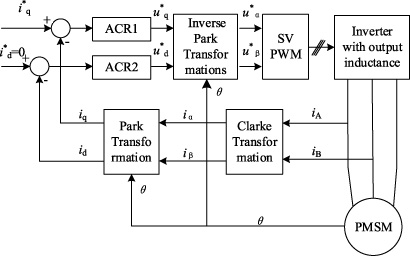
The control system.
The control system in the Fig. 2 is composed of two current closed-loop controllers, which are for the d and q-axis current control, respectively. The d-axis current reference
The performance of the LIPMSM system can be improved when driven by the converter with proper output inductance. However, the performance will be destroyed when the inductance is improper. If the inductance is not large enough, the low-inductance feature of the LIPMSM cannot be changed. The current fluctuations are still large. On the contrary, if the inductance is too large, the overall performance of the system can be greatly destroyed. The response time becomes too long, and the maximum speed becomes too small. Therefore, using an improper inductor is detrimental to the system. It is necessary to analyse the influences of the inductance on the performance of the LIPMSM. Based on these analyses, the optimal inductance can be obtained.
Influence of inductance on current fluctuations
The maximum switching frequency of general converters are typically no more than 20 kHz, which cannot meet the requirements of the LIPMSM. Therefore, current fluctuations of the LIPMSM are generated mainly in a single switching period [15]. The system equivalent circuit is used to analyse current fluctuations, instead of the average model. The value of current fluctuations is defined as the maximum width of the current waveform envelope in this paper.
The converter output inductance is regarded as a part of the motor inductance. Due to the three-phase symmetry of the motor system, the phase-A current needs to be analysed to obtain the influence of inductance on the current fluctuations. Hence, the voltage of phase A to neutral can be obtained by (2).
Since each sampling period is short enough during the motor control process, (3) can be rewritten into the following form as shown in (4).
The conclusion can be obtained by analysing (4). When motor parameters are constant, the larger the phase voltage and the longer action time are, the larger current fluctuations will be. The phase voltage of the motor (including the output inductance of the converter) is related to the output of the converter. The action time of each vector is related to the current running status of the motor and the modulation strategy of the converter. So, the motor current fluctuations are not invariable even in the same motor system, which is changed with the status of the motor. And it is impossible to calculate a specific value of the current fluctuations accurately. Therefore, the concept of average current fluctuations is used in the place of the real-time current fluctuations.
The current is directly related to the output voltage of the converter. The output voltages of the converter are obtained by analysing the converter circuit as shown in Fig. 1. The phase voltages are shown in (5).
During the operation of the motor, there are six symmetrical sectors. So, only the sector I is considered to analyse the current fluctuations. The three vectors that will be acted upon the motor are the active vectors (1,0,0), (1,1,0) and the zero vector. When the three vectors are applied, the phase-A voltage is as shown in (8). Where U
dc is the bus voltage.
According to (4) and (8), Δi
A
is largest when the active vector (1,0,0) is applied to the motor for a whole switching period T
s
. Generally, the back EMF and resistance of such LIPMSMs are small. The effects of back EMF and the resistance voltage drop can be neglected. The maximum current fluctuations Δi
max can then be simplified as shown in (9).
The seven-segment modulation strategy is adopted as the modulation strategy for the converter. It is difficult for one single vector to act over the whole switching period. Therefore, the average current fluctuations Δi
avg
is less than Δi
max. The average current fluctuations are the current fluctuations for a certain working condition, generally, the rated working condition in this paper. The Δi
avg
can be obtained by adding a modified coefficient k
i
to the Δi
max, which as shown in (10).
According to (9) and (10), Δi avg can be considered to be inversely proportional to the inductance, and proportional to the bus voltage and the switching period of the converter. Therefore, the current fluctuations can be reduced effectively by increasing the output inductance of the converter.
In some applications, the motor is required to be able to run at the speed that is higher than the rated speed. Therefore, the maximum speed is one of the key performance metrics of the system. The usual method is to use flux weakening to make the motor reach higher speed. However, the LIPMSM has poor armature reaction, which makes it different to increase the motor speed by utilizing flux weakening [15,26]. Fortunately, the back EMF of the LIPMSM is small enough, which makes it possible for the motor to achieve high speed without flux weakening. The maximum speed is defined as the maximum speed without utilizing flux weakening in this paper. Here, the influence of the inductance on the maximum speed is analysed.
It is assumed that current fluctuations are acceptable when the LIPMSM is driven by the converter with output inductance. In this paper, the i
d
= 0 control strategy is adopted. So, there is only q-axis current. The current is in the same phase with the no-load back EMF. Assume that the motor is in a steady state, then the motor voltage vector equation can be as shown in (11).
The magnetic circuit of the LIPMSM is not saturated. So, if temperature variation is neglected, the flux 𝜓
f
, and the q-axis inductance L
q
(which is equal to 1.5L
ms
) are nearly unchanged for different operation conditions. The resistance is too small to be of any effect, which is neglected for ease of calculation. The maximum speed can be obtained from (11) as shown in (12).
The conclusion drawn from (12) is that the maximum speed of the motor is related to the bus voltage, the motor flux, and the phase inductance. If the converter and the motor are pre-selected for implementation, then the only accessible variable for the maximum speed is the output inductance of the converter. The maximum speed decreases with the increase of the inductance. Therefore, the maximum inductance for the given application is limited by the index presented in (12).
One of the best advantages of LIPMSM is that the response time of the current is generally very short. Therefore, the current response time is one of the key performance metrics of the system. If there are requirements for the current response time for the given application, then the influence of the inductance on the current response time must be taken into consideration to appropriately select the inductance.
It is assumed that the motor can operate normally with acceptable current fluctuations after increasing the inductance. In this paper, the response time is defined as the time that the motor current rises from 0 to the maximum current. Since the i
d
= 0 control strategy is used, only the response time of q-axis current need to be considered. The resistance is small to be of any effect, which is neglected for ease of calculation. The q-axis voltage equation from the motor model (1) is adapted to obtain (13).
Integrate both sides of (13) to obtain (14):
Solve (14), the response time t
up
can be obtained, where L
q
= 1.5L
ms
.
According to (15), the current response time t up is only proportional to the inductance after the converter and motor are selected. If the current response time is requested to be short, then the converter output inductance should not be too large. Therefore, the maximum inductance for the given application is also limited by the index presented in (15).
According to the analysis in Sections 3.1–3.3, the current fluctuations, the maximum speed, and the current response time are impacted by the inductance. The optimal inductance is able to be obtained by using above analyses to satisfy the requirements of the LIPMSM system.
The maximum speed and current response time are used to calculate the maximum value of the inductance. By rearranging (12) and (15), (16) and (17) can be obtained to get the maximum allowable inductance.
The specific process for getting the optimal inductance is as follows:
According to the requirements of the maximum speed and the maximum allowable response time, the maximum inductance is limited by (16) and (17). The smaller value of the two equations is selected as the maximum inductance L max, which can meet the requirements of the maximum speed and response time. Then, the inductance L g that can meet the requirement of the current fluctuations needs to be calculated by using (10). If there is no specific numerical requirement of the current fluctuations, the optimal inductance can be obtained by the relation curve between the current fluctuations and inductances drawn by (10). To make the current fluctuations as small as possible and the inductance utilization rate as high as possible, the inductance near the inflection point of the curve is best. The inductance L g obtained by (10) must be smaller than the maximum inductance L max. If the inductance L g is smaller than the maximum inductance L max, the inductance L g is the optimal inductance. Otherwise, the maximum inductance L max is the optimal inductance. The specific process is shown in Fig. 3.
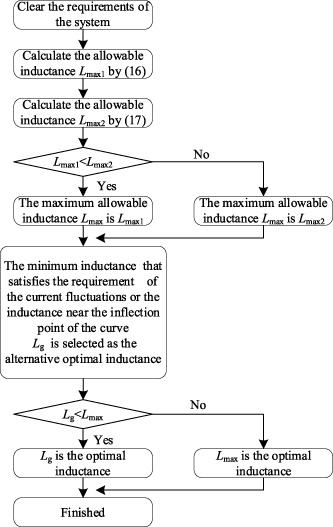
The method of obtaining the optimal inductance.
This method also guides the design of the LIPMSM inductance to suitable for the existing drive systems, which can make the LIPMSM easier to be popularized in the drive applications.
In this part, a specific example is used to verify the theory proposed in this paper through simulations and experiments. The experimental prototype DCPMSM is used as the motor of the hand mower. The process of obtaining the optimal inductance is explained in detail. The important parameters of the motor system are shown in Table 1.
Parameters of the motor system
Parameters of the motor system
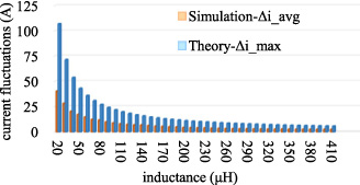
The relationship between the Δi and L ms .
Simulations of current fluctuations
In this part, the theory of the current fluctuations is verified through simulations. The current fluctuations are evaluated by measuring when PMSM operates at the rated current.
According to (9), the relationship between the theoretically calculated values of maximum current fluctuations Δi max and inductance L ms are shown in Fig. 4. As the inductance increases, the current fluctuations are decreased gradually. However, it can also be seen that for higher inductances, the unit inductance improvement in Δi max is reduced. It means that the utilization ratio of the inductance becomes lower. The relationship between average current fluctuations and inductances is obtained through simulations as shown in Fig. 4. The trend of the results of simulations is consistent with that of theoretical calculations. It confirms the expected proportional relationship between Δi max calculated by (9) and Δi avg obtained by simulations, where this proportional constant is k i as described in (10). The k i corresponding to each simulation test point as shown in Fig. 5, which is approximately 0.4. The Δi avg can then be calculated using (10) after the coefficient k i has been determined without the need of complicated simulations or experiments. Or, the coefficient k i can be also obtained through a few simple simulations.
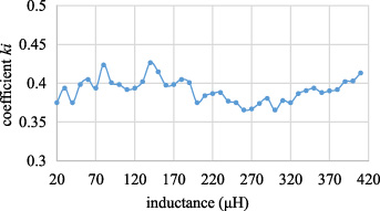
The calculation results of the coefficient k i .
To observe the influence of different inductance on current fluctuations more clearly, the current when using a small inductance, an inductance evaluated at the inflection-point and a large inductance are compared in detail in Figs 6, 7 and 8. The inductances are 50 μH, 170 μH, and 250 μH, respectively. The inductance at the value of 170 μH is the inductance evaluated at the inflection point. The Δi avg is reduced greatly from 17 A to 5 A when the inductance is increased from 50 μH to 170 μH. The improvement in performance of the current is significant. When the inductance is larger than 170 μH, the reducing value of the current fluctuations for unit inductance is noticeably reduced. The current fluctuations are reduced only 2 A when the inductance is increased from 170 μH to 250 μH. The simulation results of the current fluctuations are consistent with the theoretical results.

The simulation waveform of motor phase current when L ms = 50 μH.
The simulation waveform of motor phase current when L ms = 170 μH.
The simulation waveform of motor phase current when L ms = 250 μH.
In this part, the theory of the maximum speed is verified through simulations. To make the test procedure simple and leave a certain margin, the current is kept at the maximum phase current. The load torque remains constant. After the LIPMSM system operating, the LIPMSM accelerates from 0. The maximum speed can be obtained when the speed is stable.
The relationship between maximum speed n max and the inductance L ms is shown as Fig. 9. It shows that the maximum speed decreases with the increase of the inductance. We can find that the actual maximum speed is much smaller than the theoretical value when the inductance is not large enough. Especially, when the inductance is less than 10 μH, the motor cannot even work, and the actual speed is 0. This is because that the maximum speed calculated by (12) is based on the premise that the current fluctuations are acceptable. When the inductance is not large enough, the current fluctuates strongly to cause large torque fluctuations. So, the average effective torque of the motor is reduced. The speed will not be able to reach the theoretical value. With the increase of the inductance, the current fluctuations are reduced, and the actual maximum speed gradually approaches the theoretically calculated value. The theoretical maximum speed and the simulation results become consistent when the inductance is larger than 100 μH. The simulation value is slightly lower than the theoretical value, because some factors such as resistance voltage drop and the effect of current fluctuations are neglected in the theoretical calculation process. The simulation results are consistent with the previous analysis in this paper, and it can be considered that the theoretical maximum speed is close to the actual value when the current fluctuations ratio is less than 30%. The demand for the maximum speed is used to limit the maximum inductance. Therefore, the allowable maximum inductance can be obtained accurately by evaluating (16).
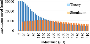
The relationship between the n max and L ms .
In this part, the theory of the response time is verified through simulations. The response time is evaluated by measuring the q-axis current i q rise time in this paper. All system conditions are kept constant, except for the q-axis current being changed from 0 A to maximum current.
The relationship between the current response time t up and inductances is shown in Fig. 10, which are calculated from (15) and measured by simulations respectively. The calculated results are consistent with the simulation results. So, the theory of the response time can be deemed correct and feasible. According to the requirements of the current response time, the allowable maximum inductance can be obtained by (17).

The relationship between simulation results of t up and L ms .
Based on the simulation analysis, the theory of the influence of the inductance on the motor system is correct and feasible. Therefore, the optimal inductance can be obtained by the method proposed in this paper. The current fluctuations are required to be small but no specific value. The maximum speed of the prototype is required to reach 9000 rpm under the rated current without the requirements of the current response time.
Because there is no requirement of the current response time. So, the maximum inductance is limited by the expected maximum speed. According to the simulation results, the maximum speed is 9036 rpm when the inductance is 230 μH, which just meets the requirement of the maximum speed. Therefore, the maximum inductance is 230 μH. In terms of reducing the current fluctuations, the larger inductance is better. However, a too-large inductor will result in some problems, such as low utilization rate of the inductance, large volume of the system, and large voltage drop of the inductor. Therefore, the optimal inductance is the minimum one that meets the requirement of the current. In this example, there is no specific numerical requirement for current fluctuations. Therefore, the inductance at the inflection point of the relation curve between current fluctuations and inductance is deemed to be the optimal inductance which is 170 μH.
According to the theorical results, the maximum inductance is 210 μH as evaluated by (16). Combining with the theoretical results of the current fluctuations, the 170 μH inductance is selected to meet the requirement of the current fluctuations, which is the theorical value at the inflection point of Fig. 4. Because the 170 μH inductance meets the requirement of current fluctuations, and does not exceed the maximum inductance (210 μH). The 170 μH inductance is the optimal inductance. The theorical result is same as the simulation result, which verifies the method of obtaining the optimal inductance is correct.
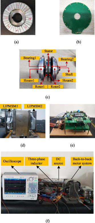
The motor and experimental system. (a) The rotor of the DCPMSM, (b) the stator of the DCPMSM, (c) the structure of the DCPMSM, (c) the back-to-back DCPMSM system, (d) the converter, (e) the experimental system.
In this part, the theory proposed in this paper is verified through experiments. The experimental platform and its components are shown in Fig. 11. The rotor and stator of the prototype LIPMSM are shown in Fig. 11-a and 11-b, respectively. The permanent magnets of the rotor are mounted by using the surface mount technology. The stator is implemented onto a printed circuit board (PCB), which can simplify the process of the production and improve the consistency. The prototype LIPMSM is axial magnetic field PMSM with the double-rotor-single-stator structure as shown in Fig. 11-c. The back-to-back motor system is shown in Fig. 11-d. It is composed of two prototype LIPMSMs. One is used as a motor, and the other is used as a load generator. The converter is shown in Fig. 11-e, which is used to control and drive the motor. The experimental system is shown in Fig. 11-f, where the oscilloscope is used to record the current waveforms; the three-phase inductor is used to change the output inductance of the converter; and the DC source is used to supply the converter.
In the experimental process, the LIPMSM operates at the rated current. The inductance of the three-phase inductor is increased by increasing the number of its windings. For every additional wingding of the inductor, the experiment is performed once for measurement. However, the current fluctuations are large when the inductance is too low, which forces the controller to activate protection and stop to work. Therefore, the experimental results cannot be obtained when the inductance is less than 20 μH. When the motor is able to work, the experimental Δi avg and its corresponding value of the theoretical Δi avg are shown in Fig. 12. The theoretical results are obtained by (10), where the coefficient k i = 0.4 is defined by the simulations. The experimental results are consistent with the theoretical value. This can verify that the theory of the current fluctuations proposed in this paper is correct.
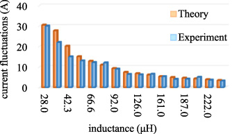
The relationship between the theoretical results of the average current fluctuations Δi avg and inductance when k i = 0.4.
The coefficient k i of each experimental test point is calculated shown in Fig. 13. The experimental k i is around 0.4 but with a slightly larger range than that of the simulation results. This is because that there are more non-ideal conditions in the experiment compared with simulations, such as the fluctuations of DC power source, non-ideal switching process for power devices, and etc. Therefore, k i can be selected to be between 0.25 and 0.5 when calculating the Δi avg by (10).
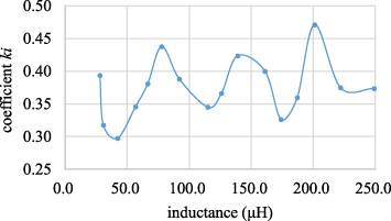
The calculation results of the coefficient k i .
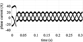
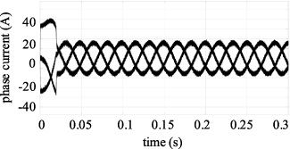
The currents when using a small inductance, an inductance evaluated at the inflection-point and a large inductance have been compared in detail. Figures 14, 15, and 16 are the phase current waveforms, where the inductances are 66.6 μH, 174 μH, and 249 μH, respectively. The current fluctuates strongly when the inductance is 66.6 μH, whose fluctuations are around 15 A. As the inductance increases to 174 μH, the current fluctuations are greatly reduced to be around 2 A. And when the inductance is increased to 249 μH from 174 μH, the current fluctuations are further reduced, but with less improvement. This is consistent with the simulation and theoretical results. Therefore, the theory and simulations proposed in this paper have been verified to be correct and feasible.

The experimental waveform of motor phase current when L ms = 66.6 μH.
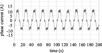
The experimental waveform of motor phase current when L ms = 174 μH.

The experimental waveform of motor phase current when L ms = 249 μH.
According to the experimental results, the inductance of 174 μH meets the requirement of the current fluctuations. And the LIPMSM can operate at around 11000 rpm at most when the 174 μH inductance is used with the rated current. The maximum speed is more than the required maximum speed 9000 rpm, which meets the requirement of the maximum speed. Therefore, the inductance of 174 μH can be selected as the optimal inductance. This result is consistent with the results of the simulations and the method proposed in this paper.
As for the LIPMSM with the coreless structure represented by the DCPMSM, the current fluctuations mechanism has been analysed. To reduce the current fluctuations and improve the performance of the LIPMSM, the converter with optimal output inductance is adopted. The optimal inductance can be obtained simply and feasibly by using the method of obtaining the optimal inductance, which is based on the influence of inductance on the LIPMSM performance. This method can guide to select the optimal inductance by the theorical calculations, which can reduce the workload on the simulations or the experiments. The LIPMSM cannot work when driven by the general converter due to the huge current fluctuations. When the LIPMSM is driven by the converter with optimal output inductance, the current fluctuations are reduced to 2 A. The maximum speed can reach 11000 rpm, which is higher than the required maximum speed 9000 rpm. And the response time is still short. The performance of the system is improved, and meets all the requirements by using the converter with optimal output inductance. At the same time, the method of obtaining the optimal inductance can also be used to guide the design of the inductance of the motor, which makes the LIPMSM have appropriate intrinsic inductance. This research is hoped to be conducive to the popularization of the LIPMSM in future applications.
Footnotes
Acknowledgements
This work was supported by the National Natural Science Foundation of China under Grant No. 51577125.