
Abstract
The magnetic gear integrated permanent magnet synchronous generator (MG-PMSG) can reduce the acoustic noise and mechanical loss, which are caused by the mechanical gear box. It also has the merits of increasing efficiency and reducing system volume when it is used for wave energy conversion system. In this paper, an improved bat algorithm (BA) based on velocity weighting factor is proposed. The improved BA is applied for the optimization design of permanent magnet (PM) to reduce the cogging torque of MG-PMSG. The numerical model is constructed by response surface methodology (RSM). The influences of key pole shape parameters on cogging torque were investigated, including the eccentric distance, the pole-arc coefficient and the permanent magnet thickness. A global optimization design is then carried out by using the improved BA, so that the magnet dimensions corresponding to the optimal cogging torque are obtained. Finally, the performances of the MG-PMSG with the optimized permanent magnet are analyzed by finite element method. Results show that cogging torque, steady torque ripple and back electromotive force (EMF) waveform distortion of the optimized MG-PMSG are reduced.
Introduction
In the environment of energy crisis, it is urgent to develop and utilize clean, renewable and alternative energies. As a kind of new energy, wave energy has attracted extensive attention and research due to its clean, renewable, rich and flexible form of power generation [1–7]. The gear box used for wave energy converter (WEC) plays an important role of increasing speed, stabilizing direction and realizing the conversion from the input power of low speed and high torque to the output power of high speed and low torque. The existing gear box is often a mechanical transmission structure. It has many disadvantages such as vibration noise, mechanical wear, normal maintenance, and so on. The magnetic gear, which is separated in space compared with the mechanical gear box, has the advantages of high conversion efficiency, small volume and low maintenance cost. It has a great application prospect in various WECs, such as point absorber, duck WEC, overtopping WEC, and so on [8–10].
A variety of integrated structures of magnetic gear and permanent magnet generator have been put forward and used in renewable energy generation. The inner rotor of a magnetic gear is coaxial connected with the generator to realize the integration of magnetic gear and generator in [11]. It has been applied to the wind power generation system. Reference [12] presented a kind of external stator magnetic gear integrated permanent magnet synchronous generator (MG-PMSG), which not only realizes the integration of mechanical structure, but also realizes the deep coupling of internal electromagnetic characteristics. References [13] and [14] realized the integration of magnetic gear and permanent magnet generator by reusing the internal high-speed rotor. This kind of integrated electromagnetic mechanism owns low-speed and high torque, and has been widely used in wave power generation, wind power generation, ship propulsion, electric vehicles and other applications. Reference [15] proposed a novel MG-PMSG, which integrates an axial-flux magnetic gear into a radial field stator. The input speed is low, so that it can be used in marine generator. The MG-PMSG has great application potential in wave power generation too. However, the cogging torque generated by the interaction of magnetic field and stator core cogging in the circumferential direction will cause torque fluctuation, and then produce vibration and noise. At the same time, the cogging torque will affect the back electromotive force (EMF) waveform and reduce the power generation quality. Therefore, in the case of wave power generation. It is necessary to take the reduction of cogging torque as the key optimization design objective.
Various methods, such as slot less windings, skewing of stator slots, skewing of permanent magnets, eccentric structure of permanent magnets and Halbach array permanent magnets, are adopted to reduce cogging torque [16–18]. In addition, using intelligent algorithms to optimize structural parameters is also an effective method to reduce cogging torque [19,20]. The bat algorithm (BA) is a novel metaheuristic optimization algorithm proposed by Yang in 2010 [21]. It is based on the echolocation behavior of micro bats. It has been applied for the optimization of BLDC motor design, power system stabilization [22,23]. Compared with simulated annealing algorithm and firefly algorithm, the BA has the advantages of simple optimization model, fast convergence rate and potential parallelism. But it also faces the problems of low accuracy and easy to fall into local optimization. In this paper, an improved BA is proposed by introducing concave time-varying velocity weighting factor to expand its search area and improve the local search ability, and it is applied to the optimal design of permanent magnet for cogging torque reduction of MG-PMSG. In Section 2, the improved BA based on velocity weighting factor is introduced. In Section 3, the basic model of MG-PMSG is introduced. In Section 4, the numerical model of cogging torque is established by RSM and the optimal design is carried out by the improved BA. In Section 5, the validity of the optimized design results is verified by the finite element method.
Improved BA based on velocity weighting factor
Principle of BA
Idealize echolocation of micro bats: These bats generate sound waves to the surrounding space when looking for food, and adjust the loudness and pulse rates of sound waves according to the proximity of their prey. When they tend to get close to the prey, the loudness decreases, while the pulse rate increases. BA mimics this idea to search the solution space of the optimization problem. It takes the position of each bat as the feasible solution and the prey as the objective solution.
Assuming that the definition domain is a D-dimension search space, the position and flight velocity of each bat at time t are updated by:
In order to improve the search performance of the algorithm, a local search method is added to BA, which generates a new solution through random disturbance as:
Further, the loudness and rate of pulses emitted by bats will be updated according the follow iterations as:
Therefore, when the bats keep approaching prey, the loudness is getting lower and the pulse rate is becoming higher, i.e.,
Exploration ability and mining ability are the two key indexes to evaluate the search ability of an optimization algorithm. Exploration ability refers to the ability to search extensively in the global space, so as to locate the local space where the optimal solution is located. Mining ability refers to the ability to search intensively in the local space to find local optimal solutions and even the global optimal solution. Generally speaking, in the early stage of search, most individuals play an exploratory role and conduct a large-scale search. As the number of iterations increases, most individuals mainly play the role of mining to conduct local optimization.
There are two parts in the velocity update formula of BA as shown in (2). The first part keeps the original velocity and direction of bat and plays the role of global search. The second part performs local search near the candidate solution. In this paper, equation (2) is modified by introducing a concave time-varying velocity weighting factor to coordinate the exploration and mining capabilities of the algorithm. In the early stage, a larger weight factor is used to expand the search domain to enhance the global search ability of the algorithm. In the later stage, a smaller weight factor is used to improve the local search ability, so as to ensure the convergence accuracy and improve the convergence speed. At this time, the BA velocity update formula is modified as follows:
For the objective function f (
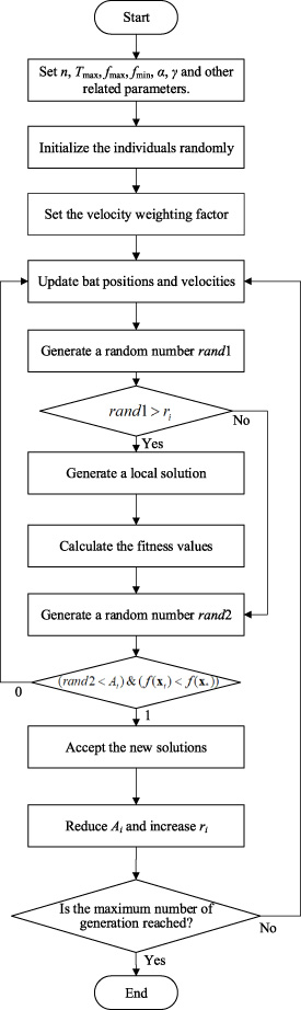
Step 1: Set the bat population size n, maximum iteration times T max, pulse frequency upper limit f max and lower limit f min, loudness attenuation coefficient 𝛼, pulse rate enhancement coefficient 𝛾 and other related parameters.
Step 2: Initialize bat positions x i (i = 1,2, …, n), velocities v i , frequencies f i (f i ∈ [f min, f max]), pulse rates r i , loudness A i . Calculate the corresponding fitness values and find out the optimal bat individual.
Step 3: Set the velocity weighting factor according to (7).
Step 4: Generate new solutions by adjusting the frequency and updating the bat positions and velocities according to (3) and (8).
Step 5: Generate a random number rand1, if rand1 > r i , generate a local solution around the best solution according to (4).
Step 6: Calculate the fitness values of all bats.
Step 7: Generate a random number rand2, if (rand2 < A
i
)& (f (
Step 8: Find the optimal solution, and judge whether the end condition is achieved. If it is satisfied, output the corresponding results, otherwise, return to Step4.
This procedure is also sketched in Fig. 1.
Flowchart of the improved BA.
In order to test the optimization effect of the improved BA, Ackley function is used to test the BA and the improved BA based on velocity weighting factor. The Ackley function can be expressed as:
Figure 2 shows the three-dimension graph of Ackley function. As can be seen that the surface of the Ackley function is uneven and it is necessary to scan a large area in order to avoid falling into the trap of local optimization. Therefore, it is usually used to detect the global convergence ability of an algorithm. The function can obtain the global minimum value 0 at (0, 0, …, 0).
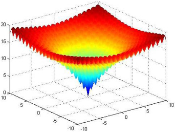
Three-dimension graph of Ackley function.
The concept of bat population average speed
Figures 3 and 4 show the fitness results and bat population average speeds of Ackley function solved by BA and improved BA. It can be seen that when solving the function, the BA encounters premature convergence problem, and can’t jump out of the local optimal solution. The solution accuracy is low and the average speed is divergent, which is not conducive to the local search of the algorithm. When the improved BA is used to solve the problem, the global optimal solution is found, and the average speed is converged. Furthermore, a bat was randomly selected from the bat population and its trajectory in the iteration process was observed. The results are shown in Fig. 5. It can be seen that the improved BA based on velocity weighting factor has the characteristics of variable direction and wide search range in the solving process, which helps the algorithm to jump out of the trap of local optimal solution and improve the accuracy and efficiency of optimization.
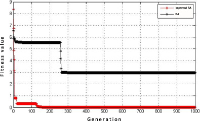
Comparison of solution results of Ackley function.

Bat population average speeds of Ackley function.
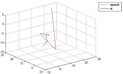
Bat search trajectories for Ackley function.
Topology model of MG-PMSG
MG-PMSG can be regarded as a permanent magnet synchronous generator coupled with a magnetic gear. The cross-section topology is shown in Fig. 6(a). From outside to inside are outer rotor, stationary ring, inner rotor and inner stator. Among them, the outer rotor permanent magnets are mounted to the inner side of the outer rotor core along the circumferential direction. The modulating pieces composed of laminated silicon steel sheets are evenly distributed in the circumferential direction of the stationary ring. The inner rotor permanent magnets are attached to both inner and outer sides of the inner rotor core along the circumferential direction. There are stator slots along the circumference of the stator, and the armature windings are embedded in the slots. Halbach array magnetization is used for outer rotor permanent magnets and radial magnetization is used for inner rotor permanent magnets, as shown in Fig. 6(b). This magnetization method can improve the air gap flux density and the torque transmission ability of the magnetic gear [8].

(a) Structure of the MG-PMSG and (b) magnetization diagram.
Parameters of proposed generator

(a) Cloud distribution of magnetic flux density and (b) distribution of magnetic force line.
Figure 7 show the cloud distribution of magnetic flux density and the distribution of magnetic force line of the MG-PMSG. It can be seen that the highest magnetic flux density of the generator appears in the local area of the stator yoke and outer rotor yoke. The magnetic flux density of the stator teeth of the generator is between 1.5 T and 2.3 T, and the magnetic flux density of the stator yoke is about 1 T, which are reasonable. The inner and outer sides of the inner rotor are equipped with 4 pairs of permanent magnet poles, so 8 wave heads can be clearly seen in the stator core. The outer rotor is equipped with 23 pairs of permanent magnetic poles, but the core part of the outer rotor cannot distinguish 46 wave heads, even 8 wave heads. There are two reasons. One of the reasons is that most of the magnetic lines of force excited by the inner rotor poles will reach the outer rotor through the middle air gap, the stationary ring and the outer air gap, forming a closed loop. While the magnetic pole distance of outer rotor is small. Therefore, the magnetic circuit is very short, and some magnetic lines of force cannot reach the inner rotor. Another reason is the self-shielding characteristic of the outer rotor pole after the Halbach array magnetization method is adopted. The magnetic field of the outer rotor pole in the outer region is greatly weakened. The four pairs of magnetic fields excited by the inner rotor magnetic poles cover up the magnetic field produced by the outer rotor magnetic poles.
Figure 8 shows the diagram of a wave power generation system with MG-PMSG. The wave energy converter is directly connected to the mechanical input port of the integrated generator, i.e., the outer rotor, to convert the wave energy into the mechanical energy of the outer rotor rotation. Then, through the magnetic field modulation effect of the stationary ring on the inner and outer air gap magnetic fields, the low-speed rotation of the outer rotor is converted into the high-speed circular motion of the inner rotor, and the mechanical energy is converted into alternating current under the interaction between the permanent magnets inside the inner rotor and the stator windings. Then the electric energy from the generator is transferred to grid with the AC-DC-AC converter and transformer.

Diagram of a wave power generation system with MG-PMSG.
MG-PMSG for wave energy conversion, which combines magnetic gear and permanent magnet synchronous generator deeply, can not only match the low-speed motion of wave, but also achieve the speed increasing ability of gear box, which can meet the operation requirements of permanent magnet synchronous generator. However, the magnetic field excited by the permanent magnets and the slots of stator core will interact to produce cogging torque in the circumferential direction. However, the torque in the air gap between the inner rotor and stator will cause problems such as torque ripple, vibration and noise, which will affect the performance of the generator. Therefore, it is necessary to reduce the cogging torque for the MG-PMSG.
In order to facilitate the analysis, the following assumptions are made:
Set the permeability of armature core to be infinite. Set θ = 0 on the center line of any inner rotor pole. The permeability of permanent magnetic materials is the same as that of air.
The cogging torque generated by the interaction between the inner rotor and the stator core can be regarded as the derivative of the magnetic field energy in the inner air gap W (𝛼)gap with respect to the angle 𝛼 between the center line of the stator teeth and the center line of inner rotor pole as:
So, the expression of cogging torque can be rewritten as:
Numerical model
Response surface methodology (RSM) is a kind of optimization method based on mathematical statistics. It can be found that the functional relationship between response and multiple factors, and display this relationship with graphic technology for intuitive analysis. Therefore, the eccentric distance d, the pole-arc coefficient a p and the permanent magnet thickness h m are used as the factors of RSM, and the peak value of cogging torque T cog-max is used as the response to study the influence of magnet dimensions on cogging torque.
According to the RSM Box-Behnken design (BBD) theory, the experimental scheme is designed. The level of each variable is shown in Table 2. Select specific 14 groups of experimental samples in the optimization parameter space, use the finite element method to model and calculate these samples, and solve the corresponding cogging torque of each sample. The results are shown in Table 3.
The quantitative relationship between the peak value of cogging torque and the three parameters of magnet is obtained by fitting as:
Analysis of variance (ANOVA) is to test the significance of F-value and corresponding P-value. For numerical model, if P-value ≤ 0.05, the relationship between input and output of regression equation is significant. If P-value >0.05, the relationship between input and output of regression equation is not significant. If significant, it means that the model is valid. Otherwise, it means that the model is not available. The lack of fit is used to express the degree of fitting between the numerical model and the actual simulation, i.e., the degree of difference between them. For the lack of fit, the corresponding P-value should be as large as possible. If P-value > 0.05, it indicates that the proportion of abnormal errors in the numerical model and the actual fitting is small.
Levels of variables
Levels of variables
BBD sample and corresponding peak cogging torque
The accuracy and reliability of (18) are further tested by ANOVA. The ANOVA results are shown in Table 4. It can be seen that the P-value of the numerical model is less than 0.05, which indicates that the fitting degree of the model is high. The P-value of the lack of fit is greater than 0.05, which indicates that the experimental error is small and can be used to analyze the future data.
In addition, residual analysis is used to measure the reliability of data and the fitting effect of numerical model. The residual results present normal distribution, which means that the data is normal and reliable. The adjusted coefficient of determination of the regression equation can evaluate the model under the influence of the number of independent variables. The ratio of the sum of squares of the regression to the sum of squares of the total deviation is equal to the square of the correlation coefficient R. It is a measure of the goodness of fit of the estimated regression equation. The larger the coefficient of determination is, the smaller the sum of squares of residuals is, so the fitting effect of regression model is better.
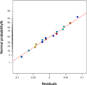
Normal plot of residuals.
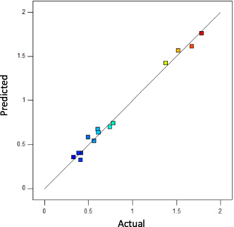
Predicted vs. Actual.
Figure 9 shows the normal plot of residuals. All data points are basically linearly distributed on a straight line, indicating that the residuals conform to the normal distribution. Figure 10 shows the fitting straight line between the actual value and the predicted value. It can be seen that the data points are basically distributed on the fitting line, indicating that the fitting degree of the two is relatively high. The model is also checked applying a numerical method utilizing the coefficient of determination. The values of R adj 2 and R 2 are 0.9907 and 0.9696, both are very close to 1. So, the fitting result has a good reference value.
ANOVA results
Based on the proposed analytical model in (18), influences of magnet dimensions on cogging torque are investigated. Variations of the peak value of cogging torque T cog-max with d, a p and h m are shown in Figs 11–13.

3D response surface of d and a p (h m = 8 mm).
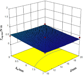
3D response surface of d and h m (a p = 0. 8).

3D response surface of a p and h m (d =15 mm).
As can be seen from Figs 11 and 13, the pole-arc coefficient has the most significant influence on the peak value of cogging torque of generator. When d and h m are fixed, and a p changes between 0.7–0.9, the peak value of cogging torque first decreases significantly and then picks up quickly. The response surface changes greatly, and the minimum value is obtained between 0.75 and 0.85. In Fig. 12, the permanent magnet thickness has more influence on the response surface than the eccentric distance. When a p and h m are fixed, and d changes between 10 mm–20 mm, the peak value of cogging torque of generator decreases first and then increases gradually with the increase of d. The minimum value is obtained between 14 mm and 18 mm. When a p and d are fixed, and h m changes between 7 mm–9 mm, the peak value of cogging torque increases with the increase of h m . These imply that lower cogging torque could be achieved by changing the eccentric distance, the pole-arc coefficient and the permanent magnet thickness, so as to improve the performance of the generator. However, due to the interaction among these three factors, the one-by-one parameter analysis cannot assure the optimal design of cogging torque.
From the aforementioned analysis, it is observed that the cogging torque of the integrated generator is significantly affected by magnet dimensions. Therefore, the improved BA is applied to the optimization of cogging torque of the integrated generator. According to the RSM fitting result, the corresponding optimization problem of improved BA is built as:
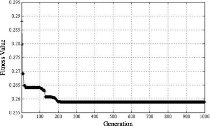
Optimization results of improved BA.
The optimization problem is solved with 1000 generations and 50 virtual bats, and the results are shown in Fig. 14. It can be seen that the fitness value of the improved BA based on velocity weighting factor is 0.2588, and the corresponding x 1, x 2, x 3 are 0.324, −0.274, −1, respectively. This means that when the eccentric distance d, the pole-arc coefficient a p and the permanent magnet thickness h m meet d =16.62 mm, a p = 0. 7726, h m =7 mm, the peak of cogging torque of the generator reaches the minimum value of 0.2588 N ⋅ m.
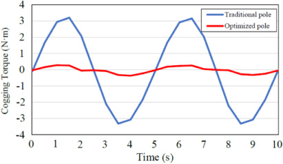
Comparison of cogging torque curves between traditional pole and optimized pole generators.
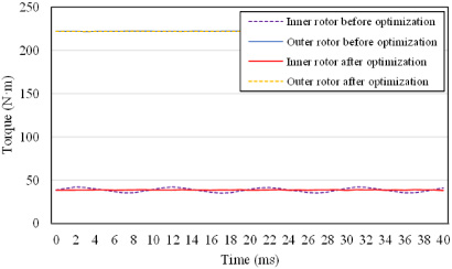
Comparison of steady torque curves between traditional pole and optimized pole generators.
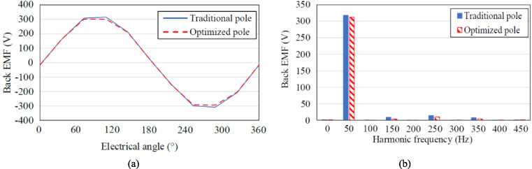
(a) Comparison of back EMF waveforms and (b) comparison of harmonic contents.
The finite element method is used to establish the integrated generator model, and the parameters of permanent magnet inside the inner rotor are set according to the optimization results. The cogging torque simulation results are shown in Fig. 15. It can be seen that the peak value of cogging torque is 0.2644 N ⋅ m, which is significantly lower than that before optimization, and basically consistent with the result of improved BA. In addition, the steady torque curves of the generators before and after optimization are compared in Fig. 16. The back EMF waveforms and harmonic contents of the generators before and after optimization are compared in Fig. 17. The cogging torque is one of the important factors that affect the torque ripple of the generator. After the cogging torque is greatly reduced, the steady torque of the inner rotor changes from (38.50 ± 3.58) N ⋅ m to (38.47 ± 0.48) N ⋅ m. The torque ripple is reduced by 86.59%, and the fluctuation amplitude is 2.49% after optimization. The effective value of back EMF decreased slightly from 227.87 V to 220 V, but the sinusoidal degree of back EMF waveform increased, and the waveform deviation factor decreased from 5.86% to 3.64%.
In this paper, in order to improve the efficiency and reliability of the MG-PMSG used in a wave energy conversion system, the optimal design of permanent magnets is carried out for cogging torque reduction by the improved BA. Specifically, to coordinate the global search and local search capabilities of bat algorithm, an improved scheme based on velocity weighting factor is put forward, and a test function is used to prove that the improved BA has good optimization accuracy and efficiency. Through the numerical model built by RSM, the influence of magnet parameters in terms of the eccentric distance d, the pole-arc coefficient a p and the permanent magnet thickness h m on the cogging torque of the generator is studied in an easier way. The influence of a p on cogging torque is the most significant, h m is the second, and d is the least. In particular, there is interaction among these three parameters. Finally, an optimization design is carried out on magnet dimensions by improved BA, achieving a satisfactory reduction of cogging torque. At the same time, the torque ripple and back EMF waveform distortion are also reduced. This can make the designed generator more suitable for stable operation of the wave energy conversion system.
Footnotes
Acknowledgements
This work was supported by National Natural Science Foundation of China (No. 51877148, No. 51577124) and Tianjin Natural Science Foundation (19JCZDJC32200).