
Abstract
The high speed magnetic levitation turbine generator used in Organic Rankine cycle (ORC) system will produce wind friction loss due to the high density of work environment and high eddy current loss in the part of permanent magnet (PM) rotor, which obviously effect the performance and stability of PM. In order to minimize the loss of PM rotor, this paper presented a comprehensive optimization design for the stator and rotor structure of turbine-generator. Firstly, the physical performances coupled with design variables, such as loss, generator power, rotor dynamic, strength and axial force of AMB were analyzed, mainly analyzed the structural variables coupled with design variables due to the effects of single constraint and the decoupling methods, which eliminated irrelevant variables in the final optimization. Neural network was used to establish agent models for each physical performance and brought into comprehensive optimization process of total PM rotor, which greatly improved the efficiency of optimization. The result of optimization is that the total rotor loss decreased 15.3% and all of other physical performance meet the requirements.
Introduction
The ORC turbo-generator system used for waste heat recovery received extensive attention in the research of distributed power generation systems due to the advantages of high efficiency and no pollution and small size [1]. As the core component of the ORC generation system, the efficiency of turbo-generator directly affects the system efficiency. Thus, magnetic levitated directly turbine connected permanent magnet synchronous generator (PMSG) have been developed rapidly in small and medium power distributed generation systems due to the lowest mechanical loss, compact structure and high power density [2]. Due to the high rotor speed and high density of work environment, the rotor of PMSG has high loss due to eddy current and wind friction, which cause the rising in temperature of PM rotor due to the difficulty of heat dissipation. Therefore, optimizing the structure of rotor to minimize rotor losses is desired to prevent overheating and degaussing of PM and improve the reliability of generator [3,4].
For the design and structural optimization of PMSG, many scholars have conducted relevant research. The comprehensive analysis [5] and the optimization for rotor volume [6], loss [7] and Thermal [8] of PMSG have been wildly researched and used for design process. However, most of them focus only on the parts of generator but ignore other structures. With the increasing integration of turbines, magnetic bearings and generator, more and more structural parameters are coupled with each other due to comprehensive performance impacts. Thus, only considering the objective-related structural parameters can no longer meet the design requirements of the integrated turbo-generator. Moreover, although optimized design of direct coupled multiphysics model based on universal finite element software is intuitive and easy to operate, but the longtime of calculate process in such transient electromagnetic field and fluid field limited the integration of more analysis and the use of global optimization algorithm.
In this paper, the rotor loss and other main performances of turbo-generator rotor are comprehensively analyzed and the optimization platform for PMSG rotor loss is built in Isight software. In this comprehensive analysis and optimization process, analytical and numerical methods are integrated flexible, and radial basis function neural network (RBF) is used to construct agent model for each physical performance. In the agent model, the design variables are decouple with other structure variables of rotor, which gets enough accuracy and greatly improves the speed of optimization. Adaptive Simulated Annealing algorithm (ASA) is used for rotor loss optimization, the result of which meet all design performance requirements for magnetic levitation turbine generator, and reduces the total rotor loss of the PMSG part by 15.3%, which achieve good optimization results.
Main structure of turbine generator.
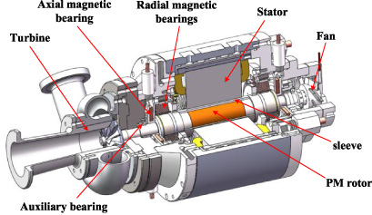
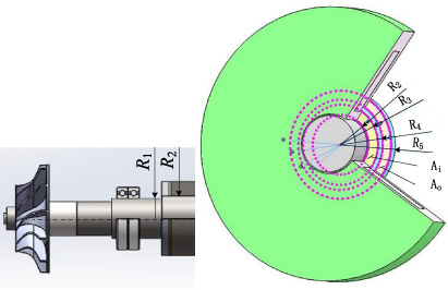
The main structure of magnetic levitation turbine generator applied to a turbine power generation system sued for ORC shown as Fig. 1. Turbine impeller is directly drove by the high-speed magnetic levitation PMSG and both located in the same shaft, which eliminates the mechanical transmission system such as reducer, coupling and mechanical bearings and have lower mechanical loss compared with traditional turbine generator, which has been recognized as the most efficient way of turbine generator set. In this paper, the stator of generator adopts gramme ring winding, which greatly shortens the length of each end of wire package and greatly improves the rotor dynamic performance. The generator rotor uses 2-poles magnet with parallel magnetisation and is supported by radial-axial integrated active magnetic bearings without extra thrust disk. In the generation power system, organic working substance turbine is expanded and cooled by the expander, partly enters to the generator cavity. This design completely seals the turbine generator and organic working substance served as the cooling medium for the generator. The fluid is vented by the fan at the end of the rotor and returning to the ORC system.
The structure of impeller shaft is shown as section view Fig. 1. The basic of rotor is a three-stage structure that is integrally formed of the two end core shafts and the motor sleeve by the interference fit. The permanent magnet is fixed in the rotor sleeve by interference fit. The rotor component of radial-axial magnetic bearing consists of a part of laminated silicon steel, a part of electric pure iron and a pure copper magnetic separator located between the two, which fix on the central spindle by interference fit. The axis extension of the rotor serves as the bearing support section. The turbine impeller is assembled on the end of the central spindles and is pressed by bolts. During operation, the aluminum alloy impeller is heated and expanded which provide a pre-tightening force against the nut. The tail of rotor is equipped with a cooling fan and is connected by flange. This kind of structure makes a compact rotor segment and an unobstructed air flue which is conducive to the heat dissipation. Meanwhile, the eliminated of separate axial thrust disc make the assembly of turbine generator more convenient.
Comprehensive analysis of turbine-generator
Multi-disciplinary performance indexes are necessary to be considered when it comes to design a high speed maglev permanent magnet synchronous generator due to its high power and high speed, such as electromagnetic, strength and rotor dynamics. Accurate analysis of these indexes is the basis for the reliability of comprehensive optimization of high speed generators.
Analysis of wind friction loss
During the operation of the generator, the generator inside is cooled by the expanded organic working substance (R245fa), the pressure is up to 0.2 MPa. The parameters of R245fa are shown in the Table 1. It can be seen that the density of R245fa at 0.2 MPa is about 10 times larger than that of conventional air, and the dynamic viscosity coefficient is slightly lower than air. Therefore, the wind friction loss is much larger than conventional air coolant at the same flow rate.
The parameters of R245fa in generator
The parameters of R245fa in generator
The wind friction loss can be calculated as follow
Wind friction loss calculated by analytic formula may be differently from the actual situation.
The comparison of analytical and CFD result shown in Fig. 2. Due to the uncertainty of the empirical formula, the loss calculation results have about 5% error compared with the fluent analysis based on finite volume method [9], while the trend of the change is quite consistent. Therefore, it does not affect the sensitivity analysis of the structural parameters and can greatly improve the analysis efficiency.
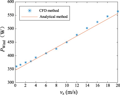
Comparison between analytical method and CFD method.
During the operation of the generator, the spatial harmonics and time harmonics of magnetic density in the air gap caused by stator slot and rectified load result in the eddy current loss in the sleeve. For the generation power systems, the current waveform varies greatly with different load, and the non-controlled rectified load is the simplest and commonly used but also the largest current harmonics load. In this paper, the ring-winding generator power model under the condition of non-controlled rectified load is established based on 2D FEA shown as Fig. 3.
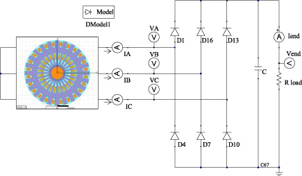
Maxwell model of ring winding permanent magnet generator and rectifier circuit.
In the Maxwell 2D finite element analysis, the vector magnetic potential A satisfies:
According to Ampere’s law, the total current density is
When the magnetic field in conductive material changes, the induced current will be generated, that is eddy current, the eddy current loss due to it is
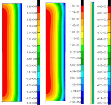
In the Maxwell analysis process, the electrical conductivity of the material is given to the rotor parts, and the loss data is taken after two cycles of analysis. The eddy current loss distribution of the rotor under rectifier circuit is shown in the Fig. 4.
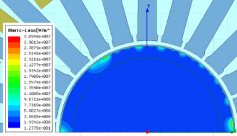
Distribution of the eddy current loss.
The rotor structure of the generator part is a cylindrical PM rotor in an alloy sleeve. The principal stress of structural parts in this type can be derived from the theoretical formula with the determined rotational speed and maximum working temperature. The formula of interference pressure is as follows:
2D axisymmetric model and stress distribution of rotor.
The analysis of rotor strength based on axisymmetric nonlinear contact model is shown as Fig. 5. It can be seen that both the maximum stress position of PM and sleeve are at the inner diameter. The material of PM is fragile and its failure yield should be judged by the first strength theory. In the center of rotor, the radial stress generated is equal to the tangential stress by the effects of interference fit and centrifugal force.
Under the combination of interference pressure and centrifugal force, the tangential stress of sleeve is as follows.
The formula of radial stress is as follows:
Because the sleeve is a plastic high temperature alloy steel, its failure yield should be judged by the fourth strength theory. The formula of its Von-Mises equivalent stress is as follows:
Where r i is the inner diameter of the part and r o is the outer diameter of the part.
Because in the Elastic mechanics theory the length of rotor is idealized as infinite, theory result is only highly consistent with the FEA results in the middle part of the rotor. The axial stress distribution in the axisymmetric FEA model is shown in Fig. 6. We can see that for the PM, the maximum radial and tangential stresses are in the middle part. For the sleeve, the equivalent stress at the axial end is slightly larger than that in the middle, but no more than 5%. Therefore, the analytical method of strength used in this paper can meet the accuracy requirements.

Principle stress axial distribution of PM and sleeve.
Due to the turbine impeller and the fan are connected directly to the rotor, the additional mass on the shaft makes the natural frequency of rotor obviously lower than that of the shaft only. However, the large rotational inertia of the impeller and the cantilever structure cause obvious gyroscopic effect during the rotation of the rotor, which makes the first critical speed increase obviously compared with the static natural frequency. According to the industry standard of turbine machinery, the rotational speed of the turbine rotor should be far away from its first critical speed of 25%. Therefore, the actual first natural frequency of the turbine should be analyzed detailed.
The motion equation of rotor-bearing system in rotating reference system is as follows:
The solution of the equation of motion is shown as (12):
The complex eigenvalue problem of rotating reference system is solved as shown in (13).
In this paper, the Timoshenko beam element is used to build the rotor model in the MSC.Patran&Nastran software. The critical speeds of the rotor under the elastic support of AMBs are obtained using the direct method of complex modal solver. In this model, the equivalent density and elasticity modulus are given to the generator part of the rotor. The rotor component of AMBs has small axial elasticity modulus and little contribution to the axial stiffness of the rotor, so it is applied as concentrated mass point to its center of mass. In order to avoid the distortion of the model, the turbine impeller and the fan are axially divided into five equivalent discs, which are also applied to the rotor in the form of concentrated mass points. The established FE model and the first bending mode shapes of the original prototype are shown in the Fig. 7. According to the comparison of modal test and simulation result shown in Table 2, the error of first bending mode frequency of rotor established by this method is no more than 5%, which has enough accuracy. Meanwhile, due to the axial stiffness of the AMB component is ignored in the model, the calculated value is smaller than the truth, which is more conservative and guaranteeing the actual rotor critical speed meeting the design requirements.
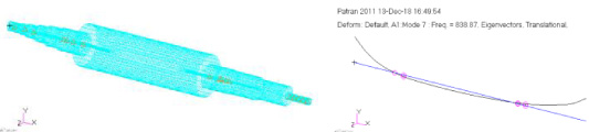
The impeller rotor FE model and the first four order mode shapes.
Turbine generator rotor simulation and test comparison results
The total mass of the designed turbine impeller rotor is about 15 kg. A pair of radial magnetic bearings have enough design redundancy to support the rotor gravity and rotational vibrations. However, under the high expansion pressure, the turbine impeller needs to bear a large axial force due to the imbalance pressure between the impeller surface and the underside. The imbalance axial force is 500 N and for the safety consideration, the maximum axial force of thrust magnetic bearing should be no less than 1000 N.
According to the topology of the rotor, the shaft shoulder is used directly as the axial thrust disc, the size of which is limited by the diameter of the generator and the shaft extension. The axial magnetic force can be obtained as follow
To decreasing the temperature rise of the permanent magnet rotor, the optimization is mainly focused on the generator parts. The radius of permanent magnet (R m ), the thickness of sleeve (H) and air gap (H a ), the outside diameter of magnet yoke (Rs_out) and the effective length of generator part (L) are selected as the variables of optimization design shown as Fig. 8, which are directly related to the eddy loss and wind friction loss.
It can be seen from the comprehensive analysis that R m , H and amount of interference (u) are coupled with each other by the constraint of structural strength. Because of the independence with u and rotor loss, this coupling relationship must be eliminated before optimization. The diameter of shaft extension (R1) is coupled with the external diameter of generator rotor but independent of rotor loss, which should also be eliminated before optimization.
In this paper, an agent model for each physical performance of selected variables is constructed based on RBF. The selected variables and the independent structure variables are decoupled in the agent model in order to avoid the misconvergence of the independent structural variables during the optimization process.
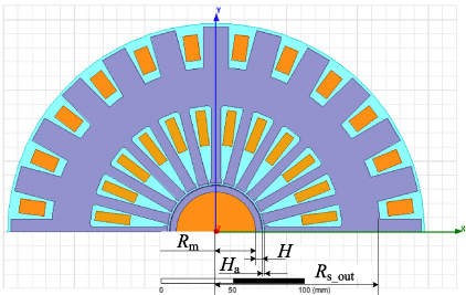
Design variable.
For a determined permanent magnet size, the determination of the minimum effective sleeve thickness (H min ) can be directly used as a basis for judging the effectiveness of H and eliminating the influence of u. Therefore, it’s necessary to find the relationship between the u and H min under certain strength constraints.
First, the H min calculation platform is built based on Isight. According to the Stress calculation formula for each working condition, the relationship between the H min and u is nonlinear. For given permanent magnet size and working conditions, the following operations are constructed and the optimization algorithm is used to find the minimum of a set of parameters with multiple constraints and nonlinear coupling.
The independent variable is:
The objective function is:
The constraint condition is:
Calculate the permanent magnet from 25 mm to 32 mm with an interval of 0.5 mm, and construct a proxy model for the 16 points obtained, use radial basis neural network to fit the data, and use the five data points for error analysis. The result is shown in the Fig. 9.
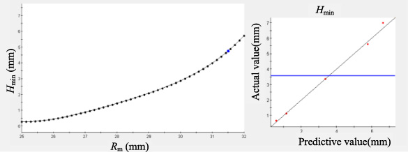
Agent model for H min .
The solution of the critical speed requires completely determining each structural dimensions of the rotor. Due to the axial magnetic tension constraint, the rotor extension diameter needs to decrease with a decrease of the outer diameter of the rotor to ensure sufficient thrust disk area. Since the shaft extension serves as a bearing support section, the dimensional requirements of auxiliary bearing inner diameter and protection gap make the shaft extension diameter impossible to change continuously. For the determined generator diameter, the following operations are constructed to calculate the corresponding maximum allowable shaft extension dimension. The variables are shown as Fig. 10.
Structure of rotor extension and axial magnetic bearing components.
The independent variable is:
The objective function is:
The constraint condition is:
Constrained by the requirements of impeller support and mechanical bearing inner diameter, the range of objective function is
According to the above calculation process, all the dimensions of the impeller shaft under a set of design variables are obtained, and the first critical speed (f1) of the rotor can be calculated. The fitted result of the agent model for f1 shown as Fig. 11. It can be seen that due to the step change of shaft extension when the diameter of generator rotor is small, the variable of f1 is nonlinear.
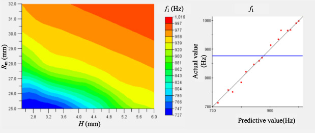
Agent model for the 1st circuit speed.
The objective function is the sum of rotor eddy current loss and wind friction loss of the generator part, only related to design variables. The constraints of generator include generated power and effective current. The amount of generated power under the rectifier circuit is calculated from the electrical parameters of resistance load. The effective current is equivalent with all harmonic current.
Accuracy test for agent model
Each agent model needs to meet the criteria for accuracy testing. In this paper, the agent model is evaluated using error squared (R2) and relative root mean square error (RMS). The optimal Latin Hypercube design was used to sample the independent variables randomly in the defined domain, and the theoretical values were compared with the model predictions.
The calculate of R2 is
The calculate of RMS is
The accuracy test results of the agent models for each physical performance in this paper are shown as Table 3. It can be seen that each agent model achieves high accuracy and meets the requirements.
Results of accuracy test for each agent model
Sensitivity analysis of objective functions
Using Optimal Latin Hypercube design to randomly sample the design variables in the defined domain and analyze the contributions to the objective function. The Pareto contribution rate shown as Fig. 12. Eddy current loss is most sensitive to the change of air gap and thickness of sleeve. Wind friction loss is most sensitive to the change of wind speed in air gap, which is corresponding to the rotor diameter. The relationship between loss and most sensitive independent variables shown as Fig. 13 and Fig. 14. Wind friction loss is basically linear with the changes of R m and L. For eddy current loss, both the increase of H a and H will decrease the magnetic density in the air gap, but the increase of H also means the decrease of conductor volume, thus eddy current loss is nonlinear with the changes of H a and H.
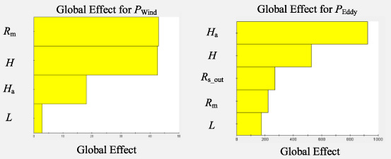
Sensitivity analysis of objective functions.
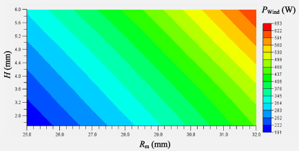
Influences of independent variables to objective functions.
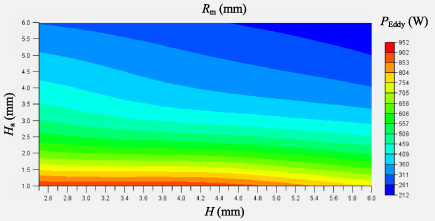
Influences of independent variables to objective functions.
In this paper, the goal of optimization is the sum of wind friction loss and eddy current losses of the generator part. It can be seen from the analysis above, the effects of independent variables on total losses is nonlinear, and each constraint function is also nonlinear or discrete. Therefore, it is necessary to select a suitable global optimization algorithm to prevent optimization from being limited to a certain local area. In this paper, ASA is applied to the optimization. ASA originates from the principle of solid annealing. Starting from a higher initial temperature, with the constant decrease of temperature parameters, the probability jump characteristics are combined to randomly find the global optimal solution of the objective function in the solution space, which is very suitable for solving highly non-linear problems with short running analysis codes [12].
The rotor loss optimization process is as follows. It can be seen from the agent model for H min that small diameter permanent magnet rotors require only a very thin sleeve to meet the strength constraints. However, in the rotor structure described in this paper, the sleeve not only protects the permanent magnet, but also bear the axial connection effect. Thus, the minimum thickness of the sleeve is not less than 3 mm.
The independent variable is:
The objective function is:
The constraint function is:
The constraint on independent variables is:
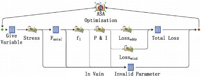
The optimization process is shown as Fig. 15. In the optimization process, constraint analysis is firstly performed for given independent variables, and total loss will be calculated when the constraints are fully satisfied and a maximum value will be given to the objective function when the constraints are not satisfied. ASA optimize across the entire domain which will gradually tend to the effective range of independent variables and finding satisfying result that meet the optimization requirements. Based on the aforementioned mathematical model and optimization logic, the multiphysics comprehensive optimization design platform is built in Isight shown as Fig. 16. Each completed agent models are added to the design path as a separate module and determine whether the constraint condition is satisfied at the output path. In this platform, each iteration step takes a very short time, which is greatly improved the optimization efficiency.

Logic of optimization.
Comprehensive optimization platform based on Isight.
The result of Isight optimization platform shown as Fig. 17. The process iterates 1011 times to stop the optimization. The value of independent variables, objective and constraint function before and after optimization shown as Table 4. The total rotor loss of the generator part decreased 15.3% and the remaining performances all meet the constraint requirements.
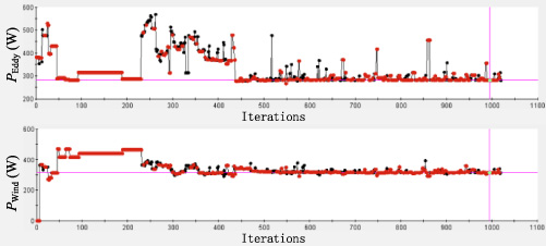
Results of optimization process.
Parameter comparison before and after optimization
Structure stress of rotor after optimization
After the optimization, put the radius of the permanent magnet and the thickness of sleeve into the reversed H min calculation process, obtain the minimum amount of interference that meets stress requirements is 0.07 mm. In that case, the maximum stress of each component shown as Table 5 and meet the requirements of structure strength.
In this paper, the magnetic levitation turbine generator is optimized comprehensively for the object of rotor loss in PMSG part. The physical performances and structure parameters coupled with design variables are analyzed. Through solving the multiple constraint problems reversely, the solution domain of the thickness of sleeve and the value of diameter of rotor extension under different design variables are obtained, which eliminated the effect of amount of interference and diameter of rotor extension on the optimization of objective functions. Based on the analysis above, agent model for each physical performance is built and brought into optimization process. The result of optimization with ASA algorithm decreased 28% total rotor loss of PMSG, which improves the stability of turbine-generator. The Logic of optimization and methods of multiphysical performances analysis can bring a significant reference for the further optimization for other performances of turbine-generator system.
Footnotes
Acknowledgements
This work was supported by Jiangsu Province key R & D Programs (BE2016180), Key Laboratory of Vibration and Control of Aero-Propulsion System Ministry of Education, Northeastern University (VCAME201902), and the Fundamental Research Funds for the Central Universities (NO. NZ2018460).