
Abstract
A proposed permanent magnetic suspension using flux path control mainly consists of a disk permanent magnet, two pairs of F-shape core and a servo motor, and controls the suspension force by changing flux path, and the load on the motor shaft is eliminated due to its symmetric offset optimal structure to make the motor reach zero power output. In order to verify the robustness of the system under external disturbances, this paper investigates and analyzes its suspension characteristics by using the simulation and the experiment. Firstly, the structure and the suspension principle of the system are introduced. Secondly, the dynamic model is established, two kinds of controllers of the system are designed with the classic PD control method. Finally, the suspension characteristics of the system are studied through the simulation and the experiment. In the process of the experiment, the system is subjected to small step disturbance or small force disturbance, under the action of the real-time control system. The experimental results show that when the system is subjected to small step disturbance or small force disturbance in the process of the suspension, the suspended object will reach a new equilibrium position under the action of the real-time control system.
Introduction
Magnetic technology has a broad application prospect in the fields of mechanical industry, aerospace, vehicles [1,2], voice coil motors [3,4] and dust-free transmission. Magnetic technology is mainly divided into permanent magnet technology, electromagnetic technology, and mixed magnetic technology. Among them, permanent magnet technology has the advantages of small size and low energy consumption, and electromagnetic technology has very good controllability [5–8]. Especially, the permanent magnet technology plays an important role in the precision instruments and dust-free environments. And the size of the permanent magnet attractive force mainly from three aspects, including the effective volume, air gap and magnetic permeability of the permanent magnet. On this basis, Sun [9–11] studied the method of controlling the suspension force by changing the flux path, and proposed a permanent magnetic suspension device with flux path control that is mainly consisting of a disk permanent magnet, two pairs of F-shape core and a servo motor. And the suspension characteristics of the device are studied to prove that it has robustness.
However, the research found that the device has a load torque generated on the motor shaft due to its structural characteristics, hence the device has a quasi-zero power characteristic. In order to reduce energy dissipation and improve motor output efficiency, an improved zero-power device with a symmetrical offset structure was proposed to eliminate the load torque and make the motor reach the zero power output [12].
The main purpose of this paper is to study the suspension characteristics of the improved device and test its anti-jamming performances. The following is the composition of this paper. In Section 2, the model, the principle of the suspension and the principle of zero power for the improved device are introduced. In Section 3, the dynamic model is established according to the characteristics of the motion, and two kinds of controllers are designed to control the suspension system. In Section 4, based on the dynamic model and controller of Section 3, we set up two kinds of simulation block diagrams to test the anti-jamming capability of the system in MATLAB/Simulink. In Section 5, we introduce the experiment setup and the structure of the prototype, and analyze the experiment results of the prototype by using the different controllers. The conclusion is in Section 6.
Improved suspension device
Model of the device
As shown in Fig. 1, the permanent magnets that two radially magnetized permanent magnet rings are mounted on both sides of the frame are fixed on the main shaft, at the same time, the magnetic poles of two permanent magnet rings are staggered 90 degrees. The fixed object is used to form the magnetic flux circuit. The shaft is connected with the servo motor with the rigid coupling; two pair of F-shape cores are placed on both sides of the permanent magnet; there is a ferromagnetic plate between two aluminum frames; one end of the suspended object is fixed through the bearing; an eddy current sensor is placed above the suspended object to measure the position of the suspended object. The advantage of the symmetrical structure is that it can be better to avoid unnecessary influence factors.
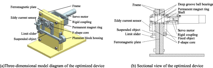
Structure diagram of the device.
As shown in Fig. 2, the method of controlling the suspension force is to change the magnetic flux passing through the suspended object in the magnetic circuit by changing the rotation angle of the permanent magnet. Fig. 2(a) shows that the initial angle of the permanent magnet is 0 degree, the magnetic flux of the permanent magnet N pole only returns to the permanent magnet S pole through the core, and there is no suspension force; Fig. 2(b) illustrates that the magnet rotated a certain angle, the facing angle of the N pole becomes bigger than the S pole in the right core, and that is reverse in the left core. Since that, the flux from the N pole in the right core is more than that in the left core. Some of the flux in the right core flow through the suspended object to the left core and is absorbed by the S pole. Consequently, there are some flux flowing through the suspended object, and the attractive force is generated to realize suspension.
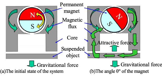
Principle of variable flux path control mechanism.
According to the structure of the permanent magnetic suspension system, the gravity of the suspended object is directly transmitted to the frame through a pair of F-shape core, and the permanent magnet and the motor do not support the gravity of the suspended object. However, due to the special structure of the F-shape core in the device, the permanent magnet of the previous device produces rotating torque of sine wave during the rotation. Therefore, in order to offset the rotational torque, the motor needs to input a small current, which will appear to have quasi-zero power characteristics in the previous device. According to the characteristics of torque in the device, the improved suspension device is designed and investigated. There are two rotating torques generated by two permanent magnet rings and two pairs of F-shape cores in the improved suspension device during the rotation, and the phase angles of two rotating torques are 90 degrees apart. Therefore, two torques of the improved device are eliminated, which will appear to have zero power characteristics in the improved device.
Dynamic model and controller
Dynamic model
Based on the characteristics of the design, the suspended object does a single pendulum movement to minimize the impact of friction on the experiment. As shown in Fig. 3, where d is the distance between the sensor and the suspended object. When the suspended object deviates from the equilibrium position, the positive direction is vertical downward; H1 is the distance between the sensor and the suspended object in horizontal position; H2 is the distance between the core and the suspended object in horizontal position; d1 is the air gap between the suspended object and the left side core; d2 is the airgap between the suspended object and the right side core; θ is the rotation angle of the permanent magnet ring; φ is the angle between the horizontal direction and the suspended position in the equilibrium; L1 is the distance between the left side core and the shaft; L2 is the distance between the sensor and the shaft; L is the length of the suspended object.

Model diagram of the system.
The suspension force model of the system and the torque model of the permanent magnet are shown in Eqs (1) and (2), respectively:
When the system is in the equilibrium position and applied the external force, the kinematics equation of the system is as follows:
When the system is in equilibrium and applied the external force, based on the Taylor expansion, the linear equations are obtained as follows:
The position of the suspended object and the rotation angle of the motor in the permanent magnetic suspension system are two main factors for the stability of the system, hence the controller controls these two variables.
According to the above requirements, the control system adopts two PD controllers that adjust the angle error and the position error, respectively. Finally, the signals of position error and angle error are calculated by the PD controller as the input current of the motor. And the clockwise rotation of the permanent magnet is a positive direction. The structure of the parallel PD control system is shown in Fig. 4.
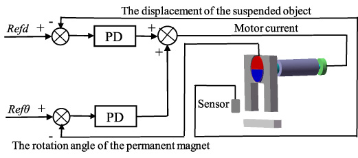
The structure of the parallel PD control system.
In the circuit for controlling the angle of the motor, since the influence of the angle feedback signal of the permanent magnet on the control is much greater than the position feedback signal of the suspended object and angle loop operates faster, the role of the position feedback signal can be neglected. The transfer function from the reference angle to the output angle is expressed as:
At the same time, the cascade control controller is designed to apply in the suspension system. Fig. 5 illustrates the structure of the cascade PD control system, where the inner loop and the outer loop are the angle loop and the position loop, respectively. It can be seen that the signal of position error is calculated by the PD controller in the outer loop to convert into the angle signal, and the signal of the angle error is calculated by the PD controller to convert into the input current of the motor. And the clockwise rotation of the permanent magnet is a positive direction.
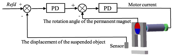
The structure of the cascade PD control system.
The inner loop controller is used to control the motor, the input term is reference angle, and the output term is the rotation angle of the motor, thus the influence caused by the air gap is neglected, and the PD control is adopted. The transfer function from the reference angle to the output angle is expressed as:
The outer-loop controller is used to control the stability of the suspended object, where the input term is the reference air gap and the output term is the air gap of the suspended object. The external disturbance force is neglected, and the PD control is adopted. The transfer function from the reference position to the output position is expressed as:
Based on the analysis above, the simulation block diagram is built to verify the stability of the suspension by using the parallel control method and the cascade control method. And the parameters of the simulation block diagram are established according to the parameters in Table 1.
Structure parameters of the system
Structure parameters of the system
The Matlab/simulink was used to analyze the anti-jamming simulation, and the measured displacement d, the rotation angle θ of the permanent magnet, and the current i of the servo motor were respectively followed. At the same time, the step displacement disturbance of 0.1 mm and the force disturbance of 0.1 N are applied to the system at 0.3 seconds, respectively.
The PD controller parameters of the parallel controller: kp1 = 180, kd1 = 0.5, kp2 = 31100, kd2 = 1210, and the simulation results are shown in Fig. 6. When the system is subjected to external disturbances, the air gap of the suspension will be increased in the initial stage of the response, and the input current of the motor is quickly increased through the PD controller, which leads to the increase of the rotation angle of the permanent magnet to provide greater attractive force. Because the initial adjustment makes the current and the angle more than the stable value, in order to maintain the system stability, the rotation angle must be reduced. The input current of the motor decreases, and after a short adjustment, it finally makes the suspended object reach a new stable state. Simulation results show that the system has a certain degree of robustness.
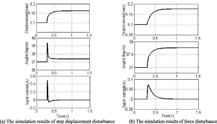
Simulation results of suspension system for the parallel PD control.
The PD controller parameters of the cascade controller: kp3 = 152, kd3 = 0.2, kp4 = 8000, kd4 = 240, and the simulation results are shown in Fig. 7. It can be seen that the change trends of the displacement signal, the angle signal, and the input current signal by using the cascade PD control method are the same as the parallel PD control. At the same time, the response time of the cascade control is shorter than that of the parallel control, which can make the disturbed system reach a stable state quickly. However, when the stability system is affected by the external disturbances, the input current will increase and produce oscillation because the position error is calculated twice to convert to the current. Therefore, the cascade PD controller is adopted to the suspension system, which can improve the response and the robustness of the system.
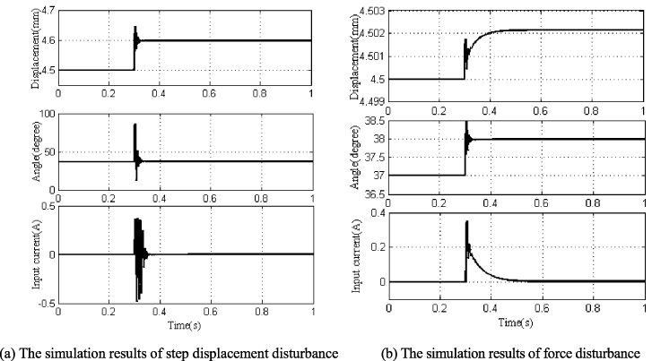
Simulation results of suspension system for the cascade PD control.
Experiment setup
Based on the analysis above, the prototype is set up according to the parameters in the Table 1. In this experiment, the drive motor is an EC-max30 servo motor, its parameters: rated voltage is 12 V, moment of inertia is 21.9 g cm2, rated revolution speed is 6590 r/min, the maximum speed is 7980 r/min. The eddy current displacement sensor adopts the EX-V series produced by Keeneshi. The material of the permanent magnet is NdFeB30, and the material of the F-shape core and suspension is permalloy 1J85.
As shown in Fig. 8, the prototype has a symmetric offset optimal structure, which consists mainly of two radial magnetized permanent magnets, a servo motor containing a gear reducer and an encoder, two pair of F-shape core of high magnetically permeable material, a suspended object, an eddy current sensor, and a bearing bracket. The material of the F-shape core is permalloy, and the material of the permanent magnet is NdFeB30, its parameters: the outer diameter is 40 mm, the inner diameter is 16 mm, the thickness is 10 mm. The air gap length is 2 mm between the F-shape core and the magnet. In order to verify the anti-interference characteristics of the system, a dSPACE real-time controller was used to build the experiment bench. And the permalloy material can enhance the magnetic permeability of the suspended object; the iron plate is used to monitor the position of the suspended object in real time.
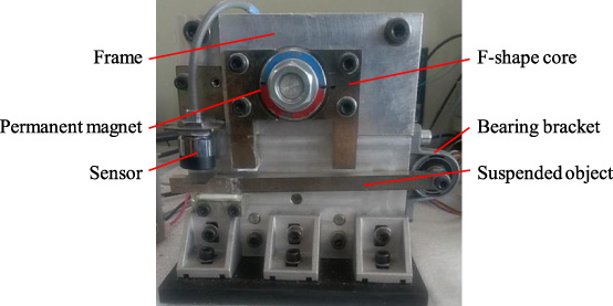
Experimental device of the suspension system.
When the system is subjected to small step disturbance or small force disturbance, under the action of the real-time control system and PD controller, the experimental results for the parallel PD control are shown in the Fig. 9. Firstly, the suspended object is in a steady suspension state, Fig. 9(a) shows the results of loading the suspended object with an amplitude signal of 0.1 mm, and Fig. 9(b) shows the results of loading the suspended object with the direction downward force of 0.1 N. The PD controller parameters: kp1 = 180, kd1 = 0.5, kp2 = 31 100, kd2 = 1210.
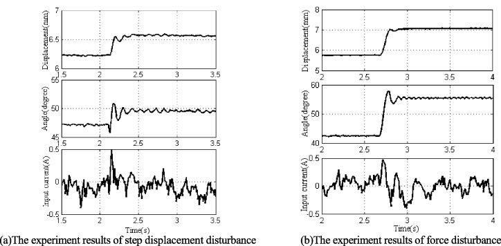
Experiment results of suspension system for the parallel PD control.
When the system is subjected to displacement disturbance and external force disturbance, the suspended object will be directly affected and the air gap will increase. And the increase of the air gap will result in the attraction force less than the gravity and make the system unbalanced. At this time, the parallel PD controller begins to adjust to increase the current of the input motor, which increases the rotation angle of the permanent magnet to provide greater attraction. Finally, the system regains a stable state in a new equilibrium position. However, the vibration of the suspended object is serious in the experiment of the displacement disturbance, and it can quickly reach stability in the experiment of external force disturbance. The reason for this phenomenon is that the force applied to the suspended object is equivalent to increasing the quality of the suspended object, which results in smaller acceleration.
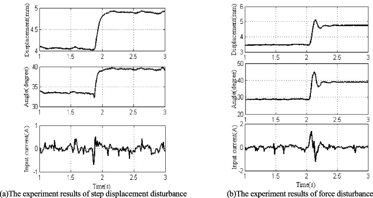
The experiment results for the cascade PD control are shown in Fig. 10. Figures 10(a) and 10(b) are the experimental results of the step disturbance and force disturbance, respectively. The PD controller parameters: kp3 = 152, kd3 = 0.2, kp4 = 8000, kd4 = 240.
Experiment results of suspension system for the cascade PD control.
As shown in Fig. 10, it can be seen that the change trends of the displacement signal, the angle signal, and the input current signal by using the cascade PD control method are the same as the parallel PD control. When the system is disturbed by the external force, the system model is affected, which will lead to the oscillation of the system than the displacement disturbance. At the same time, the signal of the displacement error is calculated twice to convert to the current signal by the PD, which will lead to increase the input current. Therefore, the input current of the cascade control is larger than that of the parallel control. However, the working principle of two control loops in the cascade controller can improve the response of the system and make the system more robust than the parallel. Due to the influence of the friction, the suspended object is not stable enough in the suspension state. Finally, the simulation results and experiment results of the parallel control and the cascade control show that the improved suspension system has certain robustness under the external disturbance.
In this paper, we present the model, the kinematic equation, the controller design, simulation and experimental results of a zero-power permanent magnetic suspension system with flux path control, and investigate the suspension characteristics on the system. The results of our study confirm that the better suspension characteristic will resist the external disturbance while exerting the disturbance. The results from both theoretical simulations and experiments show that when the system is subjected to external disturbances, the system can quickly adjust by the designed two kinds of controllers and timely track the position signals, which proves the feasibility of the suspension and the robustness of the system. At the same time, the designed cascade controller can decrease the response time. Finally, the further research such as the friction of the suspended object and the control method will be necessary to complement this study to further improve the suspension characteristics of the system.
Footnotes
Acknowledgements
This research is supported by Liaoning Revitalization Talents Program (No. XLYC1802077), Liaoning Province Innovative Talents in Colleges and Universities Support Program (No. LR2017036), Doctoral Scientific Research Foundation of Liaoning Province (No. 20170520177), and Shenyang Science and Technology Project (Z17-5-067).