
Abstract
The paper deals with the Consecutive Dual Frequency Induction Hardening of small gear wheels made of the special quality steel AISI 4340. Mathematical model of the process is elaborated. A special emphasis is put on a determination of hardness and microstructure calculated by the modified QT steel software. Exemplary computations are compared with measurements and reasonable accordance between them is achieved. An expected contour shape of the hardened zone is obtained. However for the analysed case the shape of the hardened zone is non-uniform. In order to achieve its uniform thickness along the working surface of tooth shorter heating times and higher power delivered to inductor-gear wheel system should be applied.
Introduction
The Consecutive Dual Frequency Induction Hardening (CDFIH) process consists of three stages: rapid induction heating, extremely short austenitization and cooling [1]. The process is provided for the special quality steel AISI 4340 having a tempered martensite with some particles of the tempered bainite as the prior microstructure (Fig. 1). For the CDFIH process the heating stage is realized in two consecutive stages. First the medium frequency (tens of kHz or less) induction heating to the average temperature in thin hardened zone of about the lower critical temperature Ac1 (see Fig. 2) is provided (time tMF is typically in a range a couple of seconds or less).
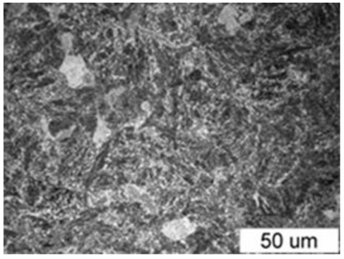
Prior microstructure of steel. Acicular tempered martensite with articles of tempered bainite. Mag × 500.

Dependence of critical temperatures on velocity of induction heating.
It is important to avoid tempering and decreasing of hardness of internal parts (zone of excessive tempering). The time break tb1 between two stages of heating is used for a shifting the gear wheel between two inductors only (tens of milliseconds). The next step is the high frequency (hundreds of kHz) induction heating (time tHF is about hundreds of milliseconds or less) to the temperature at least higher than the upper critical temperature Ac3 guaranteed termination of the austenite transformation. In practice, if we require to have the uniform austenite microstructure after the reverse transformation, the hardening temperature Th should be higher the upper critical temperature Acm.
All three critical temperatures are dependent on velocity of heating vih. The critical temperatures for heating are determined from the Time-Temperature-Austenitization diagram measured for the tested steel. Due to high velocity of induction heating reaching a level of hundreds K/s or more, critical temperatures should be modified. It means a distinct increasing of three critical temperatures (Ac1, Ac3 and Acm) of about 50–150 K (Fig. 2) [2]. Modeling of induction hardening is described in many papers for instance in [3–7]. Process of reverse transformation from the tempered martensite to the uniform austenite microstructure is described in [8]. When induction heating terminates, immediately after switching off the HF inductor (time tb2 being in a range of tens of milliseconds) the gear wheel is intensively cooled.
The paper concentrates on mathematical modelling of the hardness and microstructure fields during the CDFIH process of gear wheels (Fig. 3).
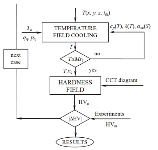
Mathematical model of the coupled temperature, hardness and microstructure fields during cooling.
As the initial condition the temperature distribution as a function of spatial coordinates and time T (x, y, z, tih) within the tooth before cooling (for the time tih = tMF + tb1 + tHF + tb2) is applied. Modeling of induction heating before cooling is described for instance in [1]. The heating stage is terminated, when the average temperature in the thin hardened contour zone satisfies relation (1). However the temperature distribution within the tooth after induction heating is non-uniform. Temperatures satisfying the condition (1) are reached in the thin zones near the surface only (Fig. 4).

Temperature distribution within the tooth after induction heating for plane of symmetry.
The computations of hardness and microstructure distributions start with a calculation of temperature field during cooling. The Flux 3D software is applied for this part of computations. Non-linear dependences of the thermal conductivity (Fig. 5) and specific heat (Fig. 6) on temperature are taken into account.
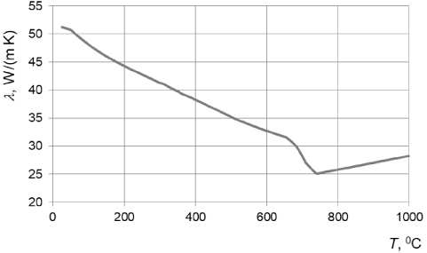
Dependence of the thermal conductivity on temperature.
Dependence of convection heat transfer coefficient during cooling 𝛼cc on temperature is determined for measured parameters (temperature of quenchant Tq, its flow rate qq. its pressure pq and dimensions of the applied cooling system (Fig. 7). However, in order to simplify the computations of the temperature field, it is necessary to take into account different average values of the convection heat transfer coefficients on three external surfaces of the tooth only and to neglect their temperature dependences (Fig. 8). Details are presented in Table 1 and in corresponding Fig. 8. The convection heat transfer coefficient on surface 2 (see Fig. 8) is equivalent to the heat contact resistance between gear wheel and the rotating mandrel [9,10]. The calculation of temperature field terminates when the average temperature in the thin contour zone begin to be smaller than the Martensite Finish Temperature Msf, which guarantees a completion of the martensite transformation.
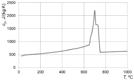
Dependence of specific heat on temperature.
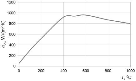
Dependence of convection heat transfer coefficient on temperature.

Average convection heat transfer coefficients on external surfaces of the tooth (description in Table 1).
Range of convection heat transfer coefficient on different surfaces of the CDFIH system for cooling (see Fig. 8)
For computations of the hardness and microstructure distributions the modified QT steel software is applied [11]. A special numerical procedure making possible to couple directly Flux 3D and QT steel codes is elaborated. The velocity of cooling vc is determined based upon several measured Cooling-Time-Temperature-continuous (CTTc) diagrams starting of different hardening temperatures T h . For the analyzed cases a range of T h changes between (850–1000°C). Based upon these diagrams, dependences of the hardness on the velocity of cooling is elaborated. Exemplary dependence of hardness on velocity of cooling for the hardening temperature T h = 970 °C is presented in Fig. 9. Figure 10 illustrates beginning of the martensite transformation (Ms – martensite start temperature line 1 in Fig. 10) and its termination (Ms f – martensite finish temperature line 2 in the same figure). Finally hardness and microstructure distributions within the tooth are determined. As a result of the computations a shape of the hardened contour zone is achieved. Computations are compared with measurements and if a condition of accordance is not satisfied, the next case is computed.
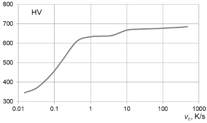
Dependence of hardness on velocity of cooling (T h = 940 °C).
In order to obtain the requested thin fully hardened contour zone, partly hardened transition zone and unchanged internal zone keeping prior microstructure with tempered martensite several cases with different configurations of the inductor-sprayer-gear wheel systems and process parameters are considered. Exemplary computations are provided for small gear wheels. Parameters of the analyzed CDFIH systems are listed below:
Gear wheel: modulus – 0.002 m, teeth number - 16, width of the tooth ring – 0.006 m, root diameter – 0.0356 m, tip diameter – 0.0269 m, hole diameter – 0.016 m.
MF inductor: external diameter – 0.054 m, internal diameter – 0.0395 m, height – 0.007 m,
HF inductor equipped with flux concentrator: external diameter – 0.061 m, internal diameter – 0.0395 m, height of coil – 0.007 m, total height (coil + concentrator) – 0.021 m, flux concentrator made of Fluxtrol 50: its external diameter – 0.0815 m, its internal diameter – 0.039 m, thickness of upper and lower cylinder – 0.005 m.
Sprayer: distance between HF inductor and sprayer – 0.02 m, external diameter – 0.085 m, internal diameter – 0.061 m.
Chemical composition of the investigated steel is presented in Table 2.
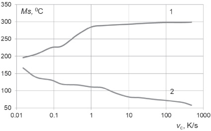
Dependence of critical temperatures (Ms (1), Ms f (line 2) on velocity of cooling.
Chemical composition of steel AISI 4340
Thermal material properties: Dependence of the thermal conductivity and the specific heat on temperature are depicted in Fig. 6 and Fig. 7 respectively.
Parameters of cooling: quenchant – polymer solution Aqua Quench 140, its concentration – 10%, its temperature – 25 °C, its pressure – 0.89 ⋅ 105 Pa, and its flow-rate – 2 ⋅ 10−5 m3/s, convection heat transfer coefficient – (see Table 1).
Modified criterial temperatures for real heating conditions: heating velocity – 230 K/s, lower critical temperature – 770 °C, upper critical temperature – 840 °C, critical temperature – 900 °C, hardening temperature – 940 °C.
Main parameters of the CDFIH process: power of the MF generator: – 60 kW, current intensity – 1385 A, heating time – 4 s, MF frequency – 36 kHz, time break between MF and HF heating – 0.3 s, power of the HF generator: – 20 kW, HF current intensity – 500 A, HF frequency – 280 kHz, time of HF heating – 0.6 s, rotation velocity – 5 r/s, time break between heating and cooling – 0.2 s.
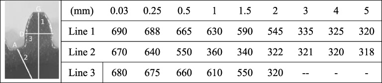
View of the laboratory set-up built in the Silesian University of Technology and the arrangement of the inductor-sprayer-gear wheel system are presented in Fig. 11 [12]. Distribution of computed hardness along three lines crossing the tooth is collected in Table 3.
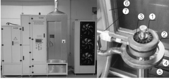
General view of the laboratory set-up and the arrangement of the hardening system, 1 – MF inductor, 2 – HF inductor, 3 – gear wheel, 4 – sprayer, 5 – mandrel, 6 – MF bus-bars. 7 – HF bus-bars.
Computed hardness distribution at different lines crossing the tooth from the surface inside the material
Let us calculate the Surface Depth Hardening (SDH) defined as a distance from the surface to the point inside the material, where the hardness decreases to 80% of its maximal value. Table 4 presents the SDH coefficient characterizing a shape of contour zone along line A…G.
Exemplary results of measured hardness distributions are presented in Fig. 12 and Fig. 13.
Hardness distribution along line A…G located at the working surface of the tooth.
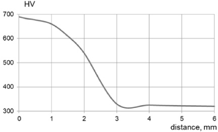
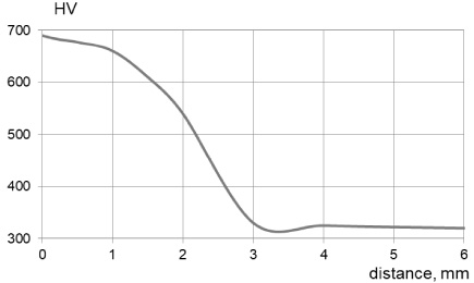
Hardness distribution along line 1 perpendicular to the point G at the tooth top.
SDH coefficient along line A (root)….G (top) at the working surface of gear wheel
Figure 12 presents hardness distribution along the line A…G of the working surface of the tooth. Obtained difference between top (point G) and root (point A) of the tooth reaches level of about 30 HV. It means not fully uniform, but matching requirements hardness distribution at the working surface of the tooth. Exemplary dependence of hardness on distance from the surface for line 1 crossing the top of the tooth is shown in Fig. 13. The obtained SDH coefficient is equal to 1.7 mm which means difference between computations and measurements of about 2,9%. For a distance from the surface higher than 3 mm hardness decreases to the value of 315 HV which means expected, unchanged prior microstructure of tempered martensite in the core of the gear wheel. Presented calculation method makes possible to achieve reasonable accordance between computations and measurements.
The proposed CDFIH process makes possible to obtain a contour shape of the fully hardened zone of investigated gear wheels. Hardness distribution inside the core of the material does not change accordingly to standard requirements. However for the analysed cases shapes of the hardened zones are non-uniform. In order to achieve its uniform thickness along the working surface of tooth shorter heating times and higher power delivered to inductor-gear wheel system should be applied.
Footnotes
Acknowledgements
The paper was prepared within the NCBiR project PBS2/A5/41/2014.