
Abstract
This paper deals with the numerical simulation and experimental investigation of magnetic flux concentrators (MFC) in particular with innovative additive manufactured MFC for induction heating applications. The novel type of magnetic flux concentrators presented in this paper is based on ferromagnetic particles embedded in ceramic matrix material guaranteeing high temperature mechanical stability and good magnetic performance. The additive manufacturing provides flexible, customized and complex geometry design of the MFC.
Introduction
Magnetic flux concentrators (MFC) are widespread used in industry in induction heating [1] and induction melting processes in order to design a desired magnetic field distribution, to increase the efficiency of the process or to reduce magnetic stray fields [1,2]. In dependence on the application the MFC are made from transformer sheets, so called laminates, from ferrites or from soft magnetic composites (SMC) [1].
The SMC are usually produced from ferromagnetic particles embedded in non-electrical conductive and non-magnetic materials. The allowed working temperature of the MFC is limited by the properties of the matrix material. The conventional MFC are usually manufactured and delivered as semi-finished products, which have to be finally machined and adapted before using.
The aim of the work presented here is the development and investigation of a new type of magnetic flux concentrators based on ferromagnetic particles embedded in ceramic matrix material in order to provide a high temperature mechanical stability, good magnetic performance and a flexible, customized, complex geometry, ready to use by the customer due to the additive manufacturing process.
Numerical and experimental investigations
In order to develop the innovative MFC numerical and experimental investigations have been carried out on an example of a linear induction coil widely used for scan heating applications, which are frequently used in industry and investigated using experiments and simulations [3–5]. Usually, the numerical investigations focus on electromagnetic and thermal fields, e.g. shown in [8,9], taking into account non-linearity of material properties [10]. The effectiveness of the MFC is analysed by the investigation of the induced power in the workpiece and the maximum temperature of the workpiece surface. Therefore, the coupled electromagnetic and thermal numerical simulation developed similarly for electromagnetic, thermal and hydrodynamic effects proposed in [7] using ANSYS has been conducted. The structure of the MFC materials has been modelled as a fine resolved matrix consisting of ferromagnetic and non-magnetic particles [6]. The concentration and distribution of the ferromagnetic particles has been varied in a wide range in order to investigate the influence of the local particles concentration on the heating effectiveness. The numerical results have been verified by experimental investigations using an induction scan heating installation, where the temperature of different workpiece materials and also the electromagnetic losses of the MFC themselves have been measured.
Numerical investigations
The magnetic field concentrator consists of ferromagnetic particles and ceramic matrix material. The matrix material preserves the mechanical and thermal stability of the concentrator, whereby the ferromagnetic particles amplify the magnetic flux density. To ensure electrical insulation, ferromagnetic particles, which are in this case iron particles, are coated with Silicon to prevent electrical conducting agglomerations that causes eddy current losses.

2D model of inductor, concentrator and workpiece with separated areas of concentrator.
Since the separation of the concentrator into magnetically conducting and non-conducting material is usually not taken into account in simulation models, a study has been conducted to investigate the effect of packing density of ferromagnetic particles in ratio to matrix material.
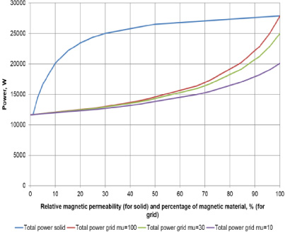
Total power of the system in dependency on packing density of ferromagnetic material and relative permeability.
Therefore, a 2D numerical simulation model of the inductor, the concentrator and workpiece, which can be seen in Fig. 1 has been created. The area of the concentrator was divided into two different sections, where different material properties have been defined. The relation of the two different sections has been varied from zero percent of magnetically conducting material representing the case where the inductor is surrounded by air, up to 100% ferromagnetic material representing an ideal concentrator surrounding the inductor.
The results of the classical modelling of the MFC as a solid block characterised by an effective relative permeability and the results of the simulation of variable packing density are shown in Fig. 2. The horizontal axis in this case represents the relative permeability from 1 to 100. The amplification of magnetic flux density is measured by total power in the system, which is the sum of the induced power in the workpiece, the power losses in inductor and MFC, represented by the vertical axis. The curves describing the power are exponentially increasing by rising packing density of the ferromagnetic material. Furthermore, the relative permeability of the magnetic material is investigated for three different values (10, 30 and 100). The curve for the solid block MFC and the curve for the magnetic material with relative permeability of 100 are ending in one point for the relative permeability of 100, because they must have the same performance in this point.
Setup of linear scan heating showing oscillating circuit, thermo- camera and workpiece.

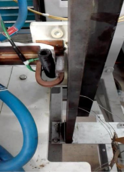
Setup of linear scan heating showing inductor, MFC and workpiece.
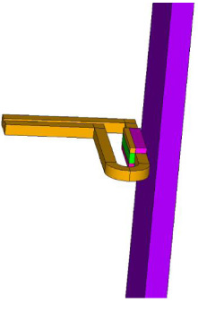
Simulation model of linear scan heating showing inductor, MFC and workpiece.
Parameters of induction scan heating experiments
The results of the solid block MFC show that there is a high impact of relative permeability on the power until a value of relative permeability 30–40. After reaching this threshold an increase of relative permeability does not result in an appropriate increase of power, because the solid block MFC shows a saturation effect. The same effect can be seen in the results of simulating packing density at 100% magnetic material: the gap of power that results varying the relative permeability from 10 to 30 is much bigger compared to the gap of power thet results varying the relative permeability from 30 to 100.
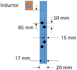
Position of thermocouples in the workpiece.
The results of packing density from 0 to 100 percent show that the effect in amplification follows an exponential curve. Therefore, the amplification performance of the MFC increases much more with higher packing density. In this case a packing density higher than 80 percent is necessary. The physical effect seems to be that with higher packing density the magnetic resistance is decreased and the losses in the MFC are reduced, as well as the total power and power density in the workpiece are increased.
Powder raw material and particle size used for MFC. Self-heating and gain factor from experiment
Combining both studies, it is obvious that the optimal MFC is a combination of first high packing density of ferromagnetic material and second of reasonable high relative permeability of the ferromagnetic material used for the particles.
It seems as if the increase in relative permeability is limited in increasing the efficiency of the system due to saturation effects. Additionally, the choice of a material with high relative permeability can result in a decrease of lifetime of both, MFC and inductor [1].
Algorithm of coupled electromagnetic and thermal simulation model.
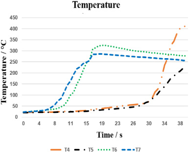
Simulated temperatures in the workpiece at the position of the thermocouples.
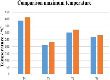
Comparison of measured and simulated maximum temperatures.
Two different test series of MFC using different ferromagnetic raw material particles, FeSi and MnZn-ferrite, have been manufactured. In order to test these MFCs, a linear scan heating process has been considered and the new MFCs and state of the art products have been tested and compared. For comparison, the maximum temperature in the workpiece and the self-heating of the MFCs are measured.
In Figs 3–5 the experimental setup of linear scan heating and the corresponding numerical simulation model are shown. In step one of the experiment the inductor starts from a specific position and moves with 20 mm/s for 2 seconds with zero power of the generator. the heating of the workpiece with 60% of the generator power follows in step two and the inductor moves with reduced velocity (5 mm/s). After 200 mm heating path the power of the generator is stopped automatically (Table 1).
During the heating process the temperature inside of the workpiece is measured by 4 thermocouples. The top thermocouple will be indicated in the results as T4 and the lowest with T7. The temperature of the surface of the workpiece and the surface of the magnetic flux concentrator is measured using a thermo-camera. The positions of thermocouples inside the workpiece are shown in Fig. 6.
The evaluation of MFCs with ceramic matrix material and ferromagnetic particles tested in experiment are shown together with the results in Table 2. Additionally, the d-sizes of the particles are listed for d10, d50, d90 and d100. The d-sizes represent the midpoint and range of the particle sizes of a given sample. The MFC are evaluated by a gain factor, which is calculated from the maximum temperature achieved in the workpiece in ratio to the maximum temperature achieved in the workpiece by heating without MFC.
After the first experiments the material of ferromagnetic particles has been changed from MnZn-ferrite to FeSi-particles. Maximum temperature in the workpiece has been increased by ca. 50% compared to the temperature of the benchmark without MFC. The temperature of the MFC due to self-heating was around 130 °C. In order to maximize the amplification of the temperature FeSi-particles has been chosen and the particle size was increased. The main difference of FeSi compared to MnZn ferrite is the higher magnetic saturation flux density which allows higher relative permeability at higher magnetic field strengths on the one hand but also higher hysteresis losses on the other hand.
The shift from MnZn ferrite as raw material to FeSi was successful due to the above mentioned combinations of advantages for induction heating applications.
The maximum achieved temperature in the workpiece was 2–2.6 times higher compared to heating without MFC. The self-heating effect caused MFC temperatures between 113–134 °C for two samples. In one case the temperature of the MFC achieved 251 °C due to particle agglomerations. In this case the amplification was highest as well.
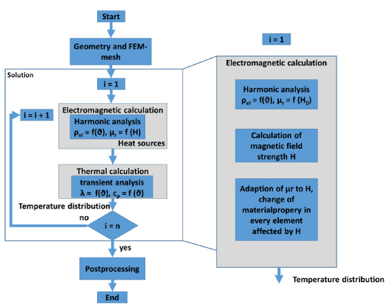
On the basis of the setup of induction scan heating including the magnetic flux concentrator has been investigated using a coupled electromagnetic and thermal numerical simulation model. Here, the electromagnetic fields are calculated in a time harmonic situation. Due to the saturation effect of ferromagnetic particles in the B-H curve, the magnetic properties inside the ferromagnetic particles are corrected using a loop of 5 to 10 steps to adapt the magnetic field intensity and change material properties accordingly. Afterwards the heat sources are given to the thermal model and the temperature is calculated according to heat transport equation. The algorithm of the coupled model is shown in Fig. 7.
The results of temperature simulation are evaluated at the same positions of the workpiece where the thermocouples were located in the experiments (Fig. 8). In Fig. 9 the results of the comparison between experimental and simulated temperatures are shown. The differences in temperatures of the thermocouples and simulated temperatures are between 5 and 10% showing a good accordance with the simulation model.
Conclusions
The investigations have shown that beside the magnetic saturation effect in the magnetic particles themselves a strong non-linear influence of the packing density of the magnetic particles is observed. Experimental investigations have confirmed that the new MFC provide a suitable magnetic performance together with low self-heating and are comparable to conventional produced composite soft magnetic materials.
The numerical simulation model has been adopted to accurately take the magnetic, geometric and thermal effects of MFC into account and can be used for detailed design of MFC for induction heating applications.