
Abstract
Alpha Magnetic Spectrometer (AMS-02) is a particle-physics detector from a module attached to the outside of the International Space Station (ISS). The temperature of the components in AMS-02 must be kept within their different operational ranges but also must be stable over both time and volume. Thermal modeling and simulations for the radiator and the electronic crates of AMS-02 were carried out by applying the Crank–Nicholson implicit solution. Based on reducing the temperature gradient of the radiator and the mass of the thermal control system, the layout of the heat pipes in the radiator was optimized to solve the overheating issue of the electronic crates. The non-operational and operational temperature dissipation for the thermal control system was calculated. The analysis results for the radiator and the electronic crates can meet the running requirements of AMS-02 on the ISS.
Introduction
Space is full of high-energy particles of many types, called cosmic rays and many of them originate in supernova explosions in distant galaxies. AMS-02 is designed as an independent module for installation on the ISS for an operational period of more than 10 years. The main scientific objectives are the search for antimatter and dark matter in cosmic rays as well as the study of cosmic rays production and propagation [1]. AMS-02 detects particles using a superconducting magnet and highly specialized, precise detectors. With careful theoretical modeling, AMS-02 can detect the ones that pass near earth and figure out how astrophysical objects leave their track in cosmic rays and how to measure that track.
Spacecraft electronic crates generate a certain amount of heat when they work in space. The heat generated by electronic crates should be dissipated to space in time, otherwise they will be overheated. In addition, in space, the overcooling of electronic crates should also be avoided. Consequently, the temperature of spacecraft electronic crates must be kept in a certain range.
The thermal environment of AMS-02 is quite harsh. Moreover, the internal thermal load generated in AMS-02 is about 2.4 KW, of which more than 60 percent comes from the electronic crates. Therefore the temperature of the electronic crates in AMS-02 should be controlled in a certain range. AMS-02 has been in space for 8 years, and the designed thermal control system works stably. In this paper, the thermal control system of AMS-02 electronic crates is studied. The analysis method and results can provide a reference for the design and analysis of spacecraft electronic crates.
Creation of the thermal mathematical model
It is impossible for a spacecraft to dissipate heat by air convection and conduction when it works in the vacuum environment of space. The main way of heat transfer is radiation, which is the only way of heat exchange between spacecraft and space [2]. The partial differential equation including heat conduction and radiation source of spacecraft thermal control system is,
Thermal modeling and simulation of the electronic crates and the radiator of AMS-02 thermal control system are carried out by thermal analysis software SINDA/FLUINT. In this paper, thermal analysis method is second-order Crank–Nicholson implicit equation. In SINDA/FLUINT, the three modes can be described individually by specifying the number, the number of their adjoining nodes and their conductance.
For diffusion nodes, the corresponding thermal balance equation in the resistor-capacitor network form is [3].
The corresponding thermal balance equation for arithmetic nodes in the resistor-capacitor network form is
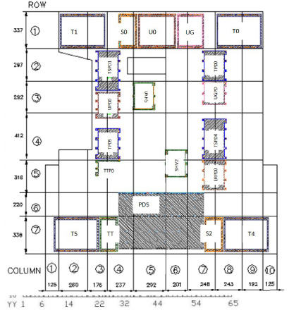
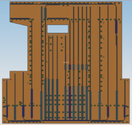
Node division and boundary nodes of electronic crates.
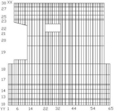
Node division and boundary nodes of electronic crates.
AMS-02 electronic crates will be overheated during operation if there is no thermal control system. AMS-02 electronic crates transmit the heat dissipated by the electronic system through the thermal control system, so that every part of the electronic system works within its corresponding temperature range. The temperature ranges of the electronic crates are −20 ∼ 50 °C under operation condition and −40 ∼ 80 °C under non-operation condition. The node division and boundary nodes of electronic crates and their radiator are shown in Fig. 1 and Fig. 2.
Thermal properties of electronic crates radiator
Conditions of AMS-02 thermal analysis
In the electronic crates and the radiator, every node is connected with adjacent nodes through the linear conductance. Thermal properties of the electronic crates radiator are shown in Table 1. In the radiator, there are three materials including the outer radiation panels, the foam sandwich and the inner heat pipes.
In the thermal analysis of AMS-02 thermal control system, the heat transfer mathematical model and the geometric model of the subsystem system are imported into the heat transfer mathematical model and the geometric model of the spacecraft system to calculate the radiation heat transfer of the launch system, the ISS and the deep-air subdetectors. The data is stored in the interface data (I/F), which is the radiation interface between orbital environments and AMS-02. By comparing the I/F data file with 259 AMS-02 thermal conditions, which are shown in Table 2, the coldest and the hottest conditions are determined, and the thermal behavior of every subsystem under the limited conditions is calculated.
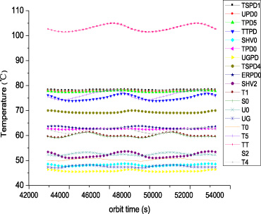
Temperature range of the electronic crates.
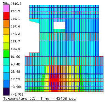
Temperature distribution of the radiator.
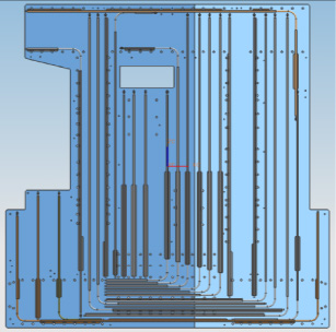
Layout 1 of heat pipes.
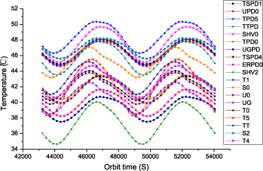
Temperature range of the electronic crates of layout 1.
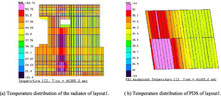
Temperature distribution of the radiator and PDS of layout 1.
When heat pipes are not installed on the electronic crates radiator, thermal analysis results under limited condition (I/F data Beta−75° −15° +25° −15°), are shown in Fig. 3 and Fig. 4.
From Fig. 3 and Fig. 4, the maximum temperature of the radiator is 211.3 °C and the maximum temperature difference is 186.9 °C. The maximum temperature is in the Power Distribution System (PDS). The temperatures of most electronic crates exceed their normal temperature range −20 ∼ 50 °C.
Layout 2 of heat pipes.
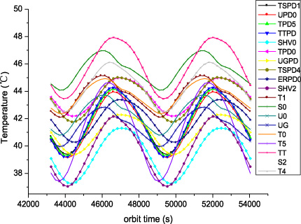
Temperature range of the electronic crates in the hottest case.
A heat pipe is a kind of high thermal conductivity material. In the field of spaceflight, heat pipes have become important devices of spacecraft thermal control [4].
The original layout of heat pipes (layout 1) is shown in Fig. 5. There are 20 heat pipes applied to the radiator, of which 18 heat pipes are vertically arranged and the other two are horizontally placed. The area ratio of heat pipes to the whole radiator is 15%. The analysis results are shown in Fig. 6 and Fig. 7.
Figure 7(a) shows the temperature distribution of the radiator of the optimization layout 1 and Fig. 7(b) shows the temperature distribution of PDS. Compared with the radiator without heat pipes, the temperature ranges of the electronic crates and the temperature gradient of the radiator have been reduced obviously. The maximum temperature of the radiator decreases to 56.7 °C and the maximum temperature gradient is 24.5 °C, which can be seen in Fig. 7(a). However, the heat at the PDS is still concentrated (Fig. 7(b)), and the temperature of electronic crate TT exceeds its normal operating range as shown in Fig. 6.
For the optimization of PDS with high temperature, one solution is to expand its heat channel by improving the heat transfer capability of PDS substrate. For example, some high thermal conductivity materials such as pyrolytic graphite are inserted into PDS or some heat pipes are inserted into its deep substrate. But this scheme will change the structure of PDS, which is relatively complex and uneconomical.
Twelve horizontal heat pipes are arranged in the PDS area of the radiator to reduce the temperature in the PDS. In order to reduce the temperature gradient of the radiator, the vertical heat pipes in the radiator are upgraded to “J” shape, and these “J” shape heat pipes are connected by horizontal heat pipes. In this scheme (layout 2), there are 24 heat pipes on the radiator, including 1 U-shaped heat pipe, 11 J-shaped heat pipes, 5 L-shaped heat pipes and 7 straight heat pipes. These configurations can not only reduce the temperature gradient of the radiator, but also transfer heat from the left to the right.
The arrangement of heat pipes at the place with maximum temperature gradient can improve the heat dissipation effect of the electronic crates and reduce the temperature gradient of the radiator. In the optimization layout, the area of the heat pipes accounts for 20 percent of the total area of the radiator. The optimization layout 2 is shown in Fig. 8.
The hottest case of AMS-02 is that AMS-02 is in operation on the ISS with I/F data Beta−75° −15° +25° −15°. Thermal analysis results under the hottest case are shown in Fig. 9 and Fig. 10.

Temperature distribution of the radiator in the hottest case.
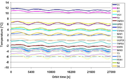
Temperature range of the electronic crates in the coldest case.
From Fig. 9 and Fig. 10, in the hottest case the temperatures of the electronic crates are within their specified temperature range. The highest temperature of the radiator is 48.2 °C, and the maximum temperature difference is 19.1 °C.
The coldest case of AMS-02 is that AMS-02 is in non-operation on the ISS with I/F data Beta−0° +15° −20° −15°. Thermal analysis results under the coldest case are shown in Fig. 11.
From Fig. 11, in the coldest case the temperatures of the electronic crates are within their specified temperature range. From the temperature distribution of the radiator in the coldest case, the lowest temperature of the radiator is −21.6 °C, and the maximum temperature difference is 32.3 °C.
From Fig. 10 and the temperature distribution of the radiator in the coldest case, the temperature gradients of the radiator decrease greatly. The analysis results are compared with the test records from IberEspacio [5]. The comparison results show that the analysis results are in good agreement with the test results and the analysis results above can meet the requirements of the AMS-02 thermal control.
The thermal analysis of the AMS-02 electronic crates on operation and non-operation condition is carried out. The analysis results show that the temperature of the electronic crates cannot met the requirements only by the radiator. By applying heat pipes with high thermal conductivity material, the thermal control system of the electronic crates is optimized. The analysis results show that the temperatures of the electronic crates meet the requirements under the coldest and hottest conditions, and the temperature gradient of the radiator is greatly reduced. The analysis and optimization of the AMS-02 electronic crates can provide a reference for the design of other spacecraft electronic crates.