
Abstract
The laser array spot thermography (LAST) is a fully non-contact and non-destructive method for the inspection of surface cracks with high efficiency. In this study, the detection capability of this method for the inspection of surface cracks in structures with curved surfaces is experimentally studied. The influence of the inspection angle on the crack imaging results is also investigated. The experiment results show that cracks in surface of the pipes with different dimeters can be detected and imaged by LAST.
Introduction
The detection of surface cracks in safety relevant structures is an important NDT task. In recent years, laser spot thermography (LST) is proposed as a promising technique for the detection of such surface flaws with its advantages such as fully non-contact and remote sensing. Many researches have been conducted for the inspection and characterization of the surface cracks by LST method [1–4]. Especially, the use of multi-spot laser source, known as laser array spots thermography (LAST), can significantly improve the inspection efficiency and reduce the data processing of this technique. Presently, the study is mainly concentrated on objects with simple shapes and geometry such as plate and cuboid [5–7]. However, in practical applications the inspection objects can be targets with arbitrary shapes and surface conditions. For example, in the IR testing of pipelines in nuclear power plants, the heating angle and shading effects caused by curved surface may hinder crack detection capability. Furthermore, the surface pattern or joint of different parts may be recognized as cracks and also provide false indications. Therefore, it is still not clear about the feasibility to inspect cracks in such surfaces by the LST or LAST.
In this study, an experimental study is conducted to investigate the feasibility of the LAST method for inspection of surface crack in curved structures. The performance of the LAST technique is experimentally examined through surface crack imaging and evaluation on stainless steel pipes with different diameters.
The paper is organized as follows: First, the experimental setup and specimen preparation is introduced in Section 2. In Section 3, a crack imaging algorithm based on wavelet transform and Hough transform is introduced to reveal the crack from thermal responses. Then, the crack imaging results under different inspection angles are shown in Section 4. A brief conclusion and discussion are concluded in Section 5.
Experimental system and specimens
The established LAST system for inspection of surface cracks is shown in Fig. 1. The experimental setup includes a continuous heat source, an infrared camera, a data acquisition (DAQ) module and a set of optical components. The heat source is a continuous-wave (CW) laser with 1064 nm wavelength and maximum power of 100 W. The thermal images were acquired by a mid-wave infrared thermal camera with a resolution of 512 × 640 pixel and frame frequency of 60 Hz. The laser output power and duration are controlled by a DAQ module of ARM, which also output camera trigger signal to synchronize the capture of infrared images and laser turn on. The optical components contain a diffractive optical element (DOE) and a plano-convex lens (PCL) laser to split the single point laser beam into a 9 × 9 laser array.
The working principle of the system is as follows. First, the controlling computer sends out a trigger signal to the DAQ module to activate the inspection procedure. Then, a periodic voltage signal is generated by DAQ module and transmit to laser driver. This voltage signal is amplified and then drive the laser to generate laser beam. At the same time, another periodic voltage signal generated by the DAQ module is also transmitted to the IR camera to synchronize data acquisition with the laser excitation. Once generated, the initial single laser beam is split into a laser beam array by the optical components. Finally, the laser spots array is exerted onto the target surface of interest, generating thermal waves and finally reveal the surface cracks. The technical specifications of equipment and details of the optical components designing have been carefully discussed in [7].

Picture of laser array spot thermography experiment system. The system contains (1) specimen and holder; (2) optical components, comprise of a laser expander, a DOE and a PCL; (3) IR camera; (4) continuous-wave laser; (5) DAQ model; (6) controlling computer.

Picture of SUS pipes specimens with diameters of 50 mm, 100 mm, 150 mm.
To examine the performance of the LAST technique, experimental evaluation is performed. As shown in Fig. 2, the specimen used in experiments are three pipes made of SUS 304. Small notches were respectively introduced in the outer surface of three pipes using a wire-cut electric discharge machining (EDM) to simulate the surface cracks. The specifications of specimens and cracks are shown in Table 1.
Specifications of four specimens and cracks
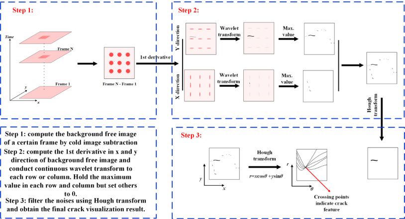
Crack imaging procedure.
In this section, a crack imaging algorithm combined with wavelet transform and Hough transform is developed to automatically identify and quantify a crack from the thermal images obtained by the LAST system. The derivative image is widely used in processing thermal signals to enhance edges and other important information while suppressing the noise. In LST, the thermal wave propagation along the surface will be blocked by a crack and cause local irregularity of images. In a similar manner, the presence of spatial discontinuities in thermal image caused by the presence of crack can be detected by the wavelet transform [8]. After that the peak values are extracted to isolate crack information from the thermal images. The Hough transform is a powerful tool in image processing field for the detection of features such as lines and circles [9]. So it can be adopted to automatically distinguish crack features and noises after the peak value filtering. Finally, the crack visualization result can be obtained. The algorithm is composed of three steps and the details of each step are outlined in Fig. 3.
Unlike the plate specimen with a planar surface, the curved surface of pipes can cause a series of negative factors to the inspection, such as the distortion of image, the unevenness of laser power distribution. Moreover, considering that in practical inspection conditions the inspection targets may be placed in a narrow space or hidden behind other structures, the laser source cannot reach the inspection region directly. Although the application of guiding fiber or reflection lens can solve the reachability problem to a certain extent, the vertical incidence of laser is not always achievable. Thus it’s also significant to investigate the influence of inspection angle to the capability of crack imaging from the point of view of practical inspection. Therefore, two kinds of laser excitation modes are considered in this work: vertical mode and angular mode (see in Fig. 4), which respectively represents the laser is heated near the crack region vertically and with a certain angle. In this work, inspection experiments under the heating angle of 30°, 45° and 60° are conducted. In experiments, the laser array is respectively generated onto the regions near the crack in the way shown in Fig. 4 to detect these defects. The laser induced on the specimen is a 4-s square pulse with 2-s heating and 2-s cooling. The power of initial laser is 80 W which means the power of each element spot in the laser array is around 1 W.
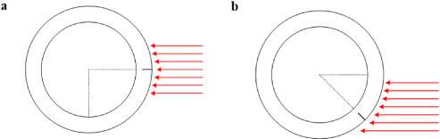
Laser excitation modes: (a) vertical mode, the crack direction is parallel to the laser direction. (b) angular mode, the angle of the crack direction towards the laser direction is a certain angle.
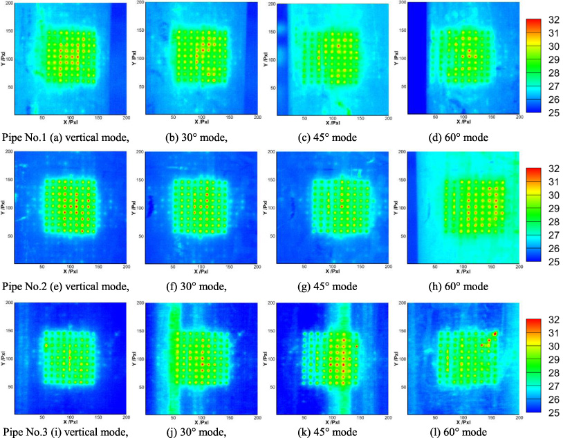
Representative thermal images of pipes obtained at 2s.
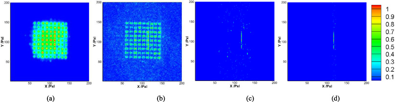
Image processing procedure: (a) cold image subtraction result; (b) 1st derivative image; (c) peak value extraction result; (d) crack extraction result by Hough transform.
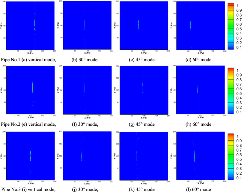
Crack visualization result from measured thermal images of pipes.
Figure 5 shows the measured temperature distribution on the pipe surface after irradiated by the 9 × 9 laser spots array after 2 s. Although the resolution of full image is 512 × 640 pixels only a 200 × 200 pixels region near the laser source heating area is selected as the region of interest (ROI). The results show that the unsymmetrical distribution of surface temperature caused by the crack can be witnessed although the curved surface reflects parts of the laser energy and cause the uneven heating effect on the surface. With the increase of laser heating angle, the crack become less clearly in original thermal images. Then the image processing procedure discussed in Section 3 is applied to the raw images. Figure 6 illustrates the results of main steps in the image processing of ROI in Fig. 5a. Final results of all the six images are shown in Fig. 7. As we expected the laser heating patterns are greatly eliminated and all the cracks are clearly revealed. Finally, the crack length is evaluated by counting the amount of pixels that visualized the crack (1 pixel sees 0.22 mm).
Crack length evaluation results
In this paper, the capability of LAST method to inspect surface cracks in curved structure surface is experimentally investigated for further applications in industry. Though the surface conditions and heating angle decrease accuracy in laser excitation and thermal image acquirement, which consequently causes decrement in thermal contrast and crack detectability, the cracks in outer surface of pipes in different diameters (50 mm, 100 mm, and 150 mm) can be visualized even with a heating angle up to 60°. The results indicate the good detection capability of LAST can be maintained for surface cracks in curved structures.
Footnotes
Acknowledgements
The authors would like to thank the National Natural Science Foundation of China (No. 11927801, 11502192), National Key R&D Program of China (2017YFF0209703) and the State Key Lab of Digital Manufacturing Equipment & Technology (No. DMETKF2018012) for funding.