
Abstract
This paper presents a new rotor shape design with optimum reverse 3rd harmonic for wound field synchronous machines to effectively enhance the saliency ratio and reduce the torque ripple in a micro electric vehicle traction system. Due to the enhanced saliency ratio, the reluctance torque is expected to be improved. The air gap flux density distribution is reshaped by the new rotor shape method, which benefits the low torque ripple. By contrast, the reverse 3rd harmonic injection is much more suitable than the general 3rd harmonic injection for increasing the effective air gap length along the q-axis for a high saliency ratio. Subsequently, three amplitudes of the reverse 3rd harmonic are studied and it is found that the optimum reverse 3rd harmonic is 1/6 of the fundamental one. To verify the effectivity of the proposed design, the original model and the ICS model are compared. Finally, all the motor characteristics, such as back electromotive force, cogging torque, and electromagnetic torque, are predicted using a 2-D finite-element method with the aid of JMAG-Designer.
Introduction
Recently, wound field synchronous machines (WFSMs) have been of interest for application in electric vehicle (EV) traction motors because they are not limited by the need for rare earth permanent magnet [1]. In EV traction applications, the permanent-magnet-free WFSMs have potentially significant advantages over commercial permanent magnet synchronous machines (PMSMs) and induction machines (IMs), including cost reduction, high power factor, loss minimization field control, and safety factor improvement. Additionally, with the development of brushless technology, the “bottleneck” of WFSM (mechanical slip rings) is no longer a very serious constraint [2].
The saliency ratio is an important parameter for improving the output torque density and extending the flux-weakening operation region without additional copper loss. Therefore, it has been paid a lot of attention when designing a novel machine topology. In a recent study, the saliency ratio enhancement was investigated in WFSMs to improve the reluctance torque [3]. However, the high saliency ratio generally causes extreme torque ripple, which leads to noise and vibration. Knowing how to resolve this trade-off would be very meaningful.
Many techniques have been proposed for torque ripple reduction. For PMSMs, the use of unequal stator teeth width [4] or unequal PM width [5] were proposed to even the saturation distribution to reduce the torque ripple. Skewing the stator or rotor is another popular technique for reducing the torque ripple, as is pole-head shaping [6]. The inverse-cosine-shaped (ICS) design is a common technique used when designing a magnetic pole, either from the magnet [7] or from an iron core [8], which does not increase the complexity and manufacturing cost of the motor. Nevertheless, most of the popular techniques for reducing the torque ripple also reducing the average torque to some extent. The method of 3rd harmonic injection into the ICS design (ICS+3rd harmonic) is well-established for application in surface-mounted PM machines (SPMMs) and interior PM synchronous machines (IPMSMs), though this can increase the average torque to some extent, with higher torque ripple compared with ICS design. However, no literature reports an investigation of the ICS+3rd harmonic method for application in WFSMs
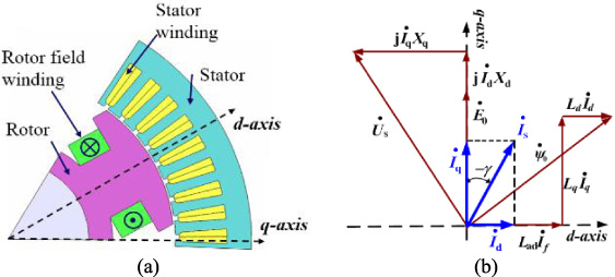
(a) Original model. (b) Phasor diagram.
Main design specifications
An ICS rotor can form a more sinusoidal air-gap flux density distribution for low torque ripple. In addition, an ICS design for WFSMs would increase the effective air gap length along the q-axis, which would reduce L q . Moreover, the method to inject reverse 3rd harmonic into the ICS design (reverse ICS+3rd harmonic) of WFSMs could further increase the effective air gap length along the q-axis. Coincidentally, unlike with SPMMs and IPMSMs, a WFSM has the normal saliency ratio defined by L d ∕L q . Thus, the saliency ratio would be increased, which is conducive to reluctance production. In particular, this approach would be expected to resolve the trade-off between torque ripple and reluctance torque. Therefore, for the first time, the reverse ICS+3rd harmonic shaping method was applied to a WFSM.
In this paper, a new rotor shape design with optimum reverse 3rd harmonic was presented for WFSMs to effectively enhance the saliency ratio and reduce the torque ripple in a micro electric vehicle traction system. A 4.7 kW WFSM with uniform air gap (the original model) and a corresponding WFSM with ICS rotor were designed for comparison to certify the effectivity of the proposed design. Furthermore, three amplitudes of the reverse 3rd harmonic on the ICS rotor were studied for optimum performance. All the characteristics were predicted using a 2-D finite-element method with the aid of JMAG-Designer.
To verify the effect of the reverse ICS+3rd harmonic rotor shape design on WFSMs, the original model and the ICS rotor model were studied for comparison. The dimensions and working conditions of all the investigated machines except for the rotor pole surface shape are same to make the comparison fair.
Original model with uniform air gap
Figure 1(a) shows the topology of the original WFSM and Table 1 lists the main design specifications. It is worth noting that the air gap between the rotor pole head surface and stator teeth head surface is uniform. The d-axis is defined as the magnetic direction produced by the field winding and the q-axis is positioned by 90 electrical degrees from the d-axis. Assuming that the space harmonics and stator winding resistance are neglected, the phasor diagram can be drawn as shown in Fig. 1(b). The electromagnetic torque can be derived as expressed in Eq. ((1)). The second term is the reluctance torque, which is almost proportional to the saliency ratio.
To obtain the sinusoidal air-gap flux density distribution desired for low torque ripple by proper shaping and proportioning of the pole shoe, the ICS rotor is normally considered. Variation of the air gap length l
gx
with shaped-arc angle x has been given as the following equation:
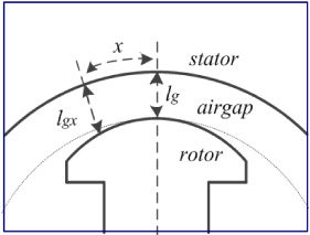
Shape of pole face.
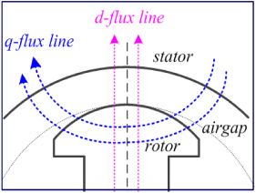
The theoretical flux path along d-q axis.
The theoretical flux path along the d-q axis is shown in Fig. 3. Obviously, the air gap is non-uniform. From the d-axis flux path, it is observed that the effective air gap length is increased when compared with that of the original model, which directly reduces the field torque. However, from the q-axis flux path, it is observed that the effective iron core is reduced when compared with that of the original model, which can increase the saliency ratio as well as the reluctance torque in Eq. (1). When the increase of the reluctance torque is greater than the reduction of the field torque, increase of the electromagnetic torque can also be obtained. To achieve the balance between the reluctance torque and the field torque needed for high quality electromagnetic torque, the ICS + reverse 3rd harmonic rotor is presented in the following.
The general ICS + 3rd harmonic rotor can be found in some studies of IPMSMs [7] and SPMMs [8], and its variation of air gap length l
gx
with shaped-arc angle x is as shown in Eq. (3).
The rotor shapes shown in Fig. 4 correspond to the different amplitudes of the 3rd harmonic that were applied to the ICS rotor of the WFSM. From Fig. 4, it can be seen that the general ICS+3rd harmonic injection tends to reduce the effective air gap length along the d-axis of the ICS rotor, which can increase the d-axis flux linkage and therefore increase its average torque. However, this was harmful to the torque ripple compared to the case with the ICS rotor, which was verified in the previous study. Meanwhile, the effective air gap length along the q-axis was reduced, compared with that of the ICS rotor. Thus, the q-axis inductance increased. For WFSMs, the normal saliency ratio is defined by L d ∕L q , which is opposite to those of SPMMs and IPMSMs. Therefore, the increased q-axis inductance means that the saliency ratio was reduced, which caused lower reluctance torque.
Rotor shapes with general ICS+3rd harmonic.

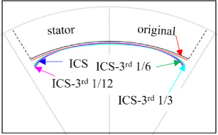
Rotor shapes with reverse ICS+3rd harmonic.
When the reverse 3rd harmonic was injected into the shaped ICS rotor head, the effective air gap length along the q-axis is increased, compared with that of the ICS rotor without harmonic injection. Thereby a higher saliency ratio could be obtained along with higher reluctance torque. Although the increased effective air gap length along the d-axis does cause reduction of the field torque, the increase of the reluctance torque could make up for the loss.
The air gap length of the reverse ICS+3rd harmonic rotor is given as Eq. (4). It is different from the existing formula in Eq. (3), and called as the reverse 3rd harmonic injection.
Figure 5 shows the corresponding rotor shapes with different amplitudes of the reverse 3rd harmonic. It can be observed that with increase of the amplitude of the reverse 3rd harmonic, the average air gap length is increased, whereas the length of the q-flux line in iron is further reduced. In the other words, the increase of the amplitude of the reverse 3rd harmonic will cause reduction of the field torque as well as increase of the reluctance torque. However, it is worth noting that the high reluctance torque normally causes a higher torque ripple. Therefore, to obtain the highest electromagnetic torque from combined field torque and reluctance torque, and to balance the torque ripple at the same time, different amplitudes of the 3rd harmonic (1/12, 1/6, and 1/3, respectively) were selected for testing.
To verify the effect of the reverse ICS+3rd harmonic rotor shapes on the electromagnetic performance, finite element analysis (FEA) by Jmag-Designer was utilized for detailed investigation.
Back-EMFs
The waveforms of back-EMFs are given in Fig. 6(a). It is shown that the original WFSM has the highest peak value, while some parts are near zero. This means the original WFSM has abundant harmonic content. However, the ICS rotor and reverse ICS+3rd harmonic rotor have smoother back-EMF waveforms. To compare their harmonic contents among the models, the FFT analysis results of each back-EMF waveform are shown in Fig. 6(b). This indicates that the fundamental component of back-EMFs is reduced due to the increased average air gap length caused by pole head shaping. Meanwhile, it can be observed that the 5th harmonic and higher harmonics are significantly reduced by both the ICS rotor and reverse ICS+3rd harmonic rotor. For the reverse ICS+3rd harmonic rotor, the fundamental component is inversely proportional to the amplitude of the 3rd harmonic injection for rotor head shaping, while the content of the 3rd harmonic is proportional.
Torque characteristics
Figure 7 depicts a comparison of cogging torques. It shows that the original WFSM has the highest cogging torque, and that the others have extremely low values. By contrast, the reverse ICS+3rd_1/6 harmonic rotor is the most effective one (reduced by 99.7%) compared with that of the original WFSM.
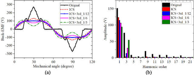
(a) Back-EMFs (b) FFT results of Back-EMFs.
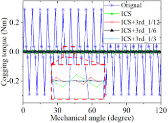
Comparison of cogging torques.

Electromagnetic torques (b) FFT results of electromagnetic torques.
Performance comparison of the investigated models with reverse 3rd harmonic injection
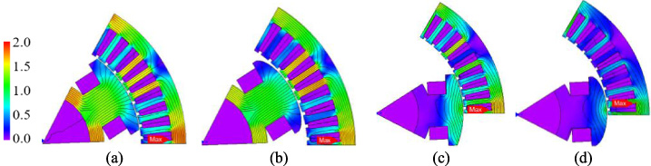
Flux distributions and flux lines. (a) d-axis of original WFSM (b) d-axis of ICS+3rd_1/6 WFSM (c) q-axis of original WFSM (d) q-axis of ICS+3rd_1/6 WFSM.
The electromagnetic torques are herein obtained by feeding the stator windings with the rated sinusoidal current excitation.
Figure 8(a) shows the variation of torques with rotor position for all the machines under maximum torque. The torque ripple of reverse ICS+3rd_1/6 harmonic rotor, defined as the peak to peak torque value versus the average torque value, is the lowest one, which is decreased by 95.0%, compared with that of the original WFSM. The comparison of the corresponding harmonic analysis of electromagnetic torques for each model are shown in Fig. 8(b), which indicates that the reverse ICS+3rd_1/6 harmonic rotor has the greatly ability to reduce the harmonic components in the electromagnetic torques.
A detailed comparison of the electromagnetic performance is shown in Table 2. It can be seen that, with increase of the amplitude of the reverse 3rd harmonic, the average air gap length is increased, and the saliency ratio is also increased. However, the average torque and the torque ripple are shown with different relationships. The reverse ICS+3rd_1/6 is the best choice for balancing the average torque and torque ripple. The average torque, reluctance torque, and saliency ratio improved by 7.3%, 153.3%, and 32%, respectively, compared with that of the original WFSM.
Most importantly, the original WFSM has the shorted average air gap length, but the lowest average torque and highest torque ripple. By contrast, the ICS rotor and reverse ICS+3rd harmonic rotor has longer average air gap lengths but higher average torque and lower torque ripple. In fact, this is due to the different saliency ratios of the WFSMs.
The saliency ratio is an important parameter for improving the output torque. Although in Section 3.2 the best rotor shape was selected, additional investigation into the saliency ratios of the original WFSM and the selected rotor shape (reverse ICS+3rd_1/6) needed to be done.
Under the same conditions of stator and winding topologies, rotor shape modification caused variation of the flux linkage and d- and q-axis inductances. The flux distributions and flux lines on the d-axis and q-axis of the original WFSM, and of the reverse ICS+3rd_1/6 WFSM, are illustrated in Fig. 9(a)–(d), respectively. Compared with the original WFSM, in the reverse ICS+3rd_1/6 WFSM the effective air gap length increased along the q-axis by finding a low reluctance pathway by-passing the non-uniform air gap. Thus, the inductance of the q-axis was reduced. Meanwhile, the d-axis flux-linkage became less prone to saturation and could be encouraged without worsening the output performance of the machine.
Conclusion
The rotor shape design for WFSMs with optimum reverse 3rd harmonic to effectively enhance the saliency ratio and reduce the torque ripple is presented in this paper. This resolves very well the trade-off between the saliency ratio and torque ripple. Greater utilization of the reluctance torque would also reduce the copper loss for a certain output power. Comparing the results, the reverse ICS+3rd_1/6 harmonic shaping method on WFSM reduced the torque ripple by 95.0%, and improved the average torque, reluctance torque, and saliency ratio by 7.3%, 153.3% and 32.0%, respectively. After qualified comparisons of SPMMs [7], IPMSMs [8] and WFSM, WFSM benefited most from reverse ICS+3rd harmonic rotor shaping.
Footnotes
Acknowledgements
This work was supported in part by the BK21PLUS Program through the National Research Foundation of Korea within the Ministry of Education, and in part by the National Research Foundation of Korea grant funded by the Korea government (Ministry of Science) (No. NRF-2020R1A2B5B01002400).