
Abstract
Magnetic flux leakage (MFL) testing is widely applied in the online detection of steel pipes. Different magnetizing directions are required for the detection of defects in different directions. As the speed of online MFL testing increases, the motion induced eddy current (MIEC) effect becomes significant, and the direction of the MIEC is perpendicular to defects in the same direction as the magnetization. Therefore, the magnetic field signal generated by the MIEC perturbation is analyzed by simulation and compared with MFL signal. It is found that the amplitude of the magnetic field signal generated by the MIEC perturbation increases with the rise of the rotational speed and magnetization. In high rotational speed and strong magnetization, the amplitude of the magnetic field signal caused by MIEC perturbation is greater relative to the amplitude of the MFL signal, providing a possibility for detecting defects that are parallel to the direction of magnetization.
Introduction
Steel pipes are important parts for transporting and storing petroleum, and it is essential to ensure the integrity of steel pipes. During the manufacture and transportation of steel pipes, defects in different directions are generated. MFL testing is widely used in the online detection of steel pipes because of its fast detection speed and high precision [1,2]. For MFL testing, defects of different directions correspond to different directions of magnetization [3]. Therefore, the axial magnetization and the circumferential magnetization of the steel pipe are required to detect circumferential defects and axial defects respectively, which causes the complication of MFL testing system. In order to achieve the detection of multi-directional defects in the steel pipe under a unidirectional magnetization, many researches have been conducted.
K. Song et al. utilized strong axial magnetization to detect omnidirectional cracks on the steel strip [4]. Y. Sun et al. studied the feasibility of detecting multi-directional defects under a unidirectional magnetization and developed a unified evaluation mechanism for defect signals in different directions by analyzing the characteristics of the signal [5]. S. Liu et al. further studied the evaluation mechanism of omni-directional defects under super-strong single axial magnetization [6]. The principle of above-mentioned researches is still based on MFL testing, which is restricted by the magnetic properties of steel pipes. When the steel pipe is magnetically saturated, the amplitude of MFL keeps constant with the increase of magnetization, which will result in the low sensitivity to narrow cracks.
To increase the detection sensitivity, J. Aguila-Muñoz et al. proposed a portable magnetic perturbation GMR-based probe and established the relationship between the defect signal parameters and the angle of the crack [7]. However, the GMR probe is easily saturated.
As the increase of online detection speed, MIEC effect was discovered during the MFL testing of steel pipes. J. Wu et al. analyzed the influence of MIEC on the circumferential magnetization of steel pipes [8]. B. Feng et al. studied the effect of MIEC on the axial magnetization and MFL signal under axial magnetization [9]. It can be seen from the previous study that as the speed increases, the MIEC effect in the steel pipes becomes obvious. Moreover, MIEC effect has been applied to detect defects in non-ferromagnetic materials [10–12].
From the generation principle of MIEC, it can be found that the direction of the MIEC is always perpendicular to the direction of magnetization, which shows the feasibility of detecting defects parallel to the magnetization. Therefore, it is possible to realize the detection of multi-directional defects under unidirectional magnetization in high speed. Based on the principle, this paper studies the influence of MIEC on the detection of circumferential defects of steel pipes under circumferential magnetization through theoretical analysis and simulation.
Theoretical analysis
The pipe is magnetically saturated by the magnetization field provided by the magnetizing coil. The magnetic yoke can enhance the magnetization field. Since the circumferential defect is parallel to the magnetization direction, the MFL signal of the circumferential defect is relatively small. According to Faraday’s law of induction, electromotive force (EMF) is induced in the pipe that rotates relative to the magnetic yoke, which can be expressed as
The MIEC will be generated in the pipe, and its density can be expressed by [13]:
From Eq. (2), it can be drawn that the amplitude of the induced current density is related to the electrical conductivity, the rotational speed of the pipe relative to the magnetizer and the magnetic field. Based on Eq. (2), it can be seen that the direction of MIEC is perpendicular to the plane formed by the direction of velocity of the steel pipe and the direction of the magnetic field, which is the axial direction of the pipe as shown in Fig. 1. Thus, the MIEC is perpendicular to the circumferential defect that will disturb the flow of the MIEC, resulting in a disturbance of magnetic field above the crack, as shown in Fig. 2. Therefore, detection of circumferential defect can be realized by measuring the magnetic field caused by MIEC perturbation above the crack.

Generation principle of MIEC in the rotating steel pipe.

Schematic of MIEC perturbation.
In order to verify the influence of MIEC on detection of circumferential defect, the 3D simulation model was established by JMAG electromagnetic simulation software, which was shown in Fig. 3. This model was composed of magnetizing coils, magnetic yoke, and a pipe. The magnetizing coil produced circumferential magnetizing field for the pipe, which was enhanced by the magnetic yoke. Considering the skin effect of MIEC [9], the outer surface mesh of the steel pipe was refined. The mesh near the defect was also refined, and the crack was created by changing characteristics of element material.
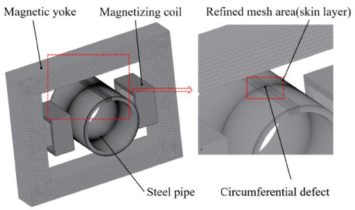
3D FEA model with refined mesh area.
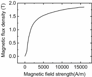
The outside diameter and the inside diameter of the steel pipe were 73 mm and 63 mm, respectively. B-H curve, which was shown in Fig. 4, was assigned to the pipe, and its conductivity was set to 4.76 MS/m. The thickness and the width of the magnetic yoke were 30 mm and 30 mm, respectively, and its permeability was set to 700. The number of the magnetizing coil was 2000.
B-H curve
First, the MIEC distribution inside the steel pipe was simulated at a rotational speed of 1000 rpm and a magnetizing current of 5 A. The induced eddy current distributed near the magnetic pole as shown in Fig. 5, which was consistent with the research result [8].
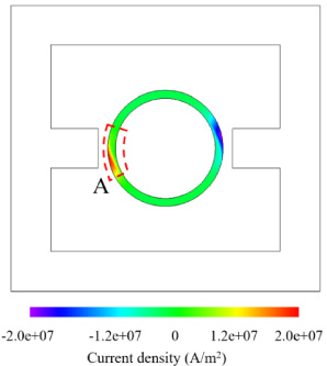
MIEC distribution in the section of the steel pipe.
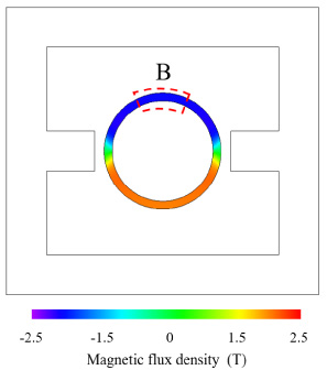
Distribution of Bθ in the section of the steel pipe.
In order to study the influence of MIEC on the detection of circumferential defect under circumferential magnetization, the MFL signal of the circumferential defect was simulated when the pipe was at the saturated magnetization. The circumferential crack was 10 mm in length, 1 mm in depth, and 0.2 mm in width. The MFL signal was extracted at a lift-off of 0.5 mm when the crack rotated to position B as shown in Fig. 6 which displayed the distribution of Bθ (the tangential component of magnetic flux density in the pipe), and its amplitude was denoted by the dashed line in Fig. 7(a). Then, the pipe rotated counterclockwise at the saturated magnetization current. The rotational speed of the pipe increased from 500 rpm to 4000 rpm with the step of 500 rpm. When the crack rotated to position A where the MIEC density is the highest as shown in Fig. 5, the magnetic field signal above the defect was extracted under 0.5 mm lift-off, and the background magnetic field signal, which was simulated in the same parameters except that there was no crack in the pipe, was subtracted to obtain the magnetic field signal generated by the MIEC perturbation. The change trend of the amplitude of the magnetic field generated by MIEC perturbation was plotted by the solid line in Fig. 7(a).

MIEC perturbation magnetic field signal amplitude (a) and MFL signal amplitude at different rotational speeds; (b) and MFL signal amplitude at different magnetizing current; (c) at different depths.
When the rotational speed is low, the amplitude of MIEC perturbation magnetic field signal is smaller than the amplitude of the MFL signal. As the rotational speed increases, the amplitude of the MIEC perturbation magnetic field exceeds the amplitude of the MFL signal. When the rotational speed is continuously increasing, the amplitude of the MIEC perturbation magnetic field will gradually slow down. This phenomenon can be explained by the fact that the resistive and inductive nature of the conductor implies a complex interaction between the primary magnetic field generated by the source current and the secondary magnetic field generated by the induced eddy currents [14]. With the increase of the rotational speed, inductive effects become prevalent, which causes the increase of the impedance of the pipe. Therefore, the increase rate of the MIEC density will slow down.
Then, the influence of magnetization on the MIEC perturbation magnetic field above the defect was simulated at a rotational speed of 1000 rpm. The magnetizing current increased from 2.5 A to 20 A with an interval of 2.5 A. When the lift-off value was 0.5 mm, the change trend of the MIEC perturbation magnetic field amplitude above the defect is plotted by the solid line in Fig. 7(b), and the dashed line is the change trend of the MFL signal amplitude of the defect with the increase of magnetizing current.
It can be seen that with the increase of the magnetizing current the magnetic field signal amplitude caused by MIEC perturbation increases faster at the initial stage compared with the subsequent stage. This is because the material of the pipe is ferromagnetic, and the B-H curve is shown in the Fig. 4.
The magnetic flux density inside the pipe increases fast at the initial stage which leads to the change trend. From the mechanism of MFL signal, it can be known that the amplitude of MFL signal remains unchanged after the material is at the saturated magnetization, which is in accordance with the change trend of MFL signal plotted by the dashed line in Fig. 7(b).
Finally, the influence of the MIEC on defects with different sizes was simulated. The depth of the defect varied from 0.5 mm to 3 mm with the step of 0.5 mm. The change trend of the MIEC perturbation magnetic field signal above the defect is denoted by the solid line in Fig. 7(c). When the defect is shallow, the amplitude of the MIEC perturbation magnetic field signal changes approximately linearly with the depth. When the depth is deep, the amplitude is almost constant due to the skin effect of MIEC.
The simulations show that the magnetic field signal amplitude caused by MIEC perturbation is smaller than the conventional MFL signal amplitude due to the low density of the dynamic eddy current at low rotational speed and weak magnetization. As the rotational speed and magnetization increase, the magnetic field signal caused by MIEC perturbation increases, and its amplitude is larger compared with the MFL signal amplitude at high speed and strong magnetization.
The traditional MFL signal amplitude tends to be constant when the pipe is at the saturated magnetization as plotted by the dashed line in Fig. 6(b), which manifests that the traditional MFL signal amplitude above the defect cannot be further increased by increasing the magnetizing current. While the MIEC perturbation magnetic field signal amplitude can be increased with the increase of the rotational speed and the magnetizing current.
The positive influence of MIEC on the circumferential defect detection under highspeed and strong magnetization provides the feasibility for detecting defects parallel to the direction of magnetization. Therefore, detecting multi-directional cracks in unidirectional magnetization could be realized and this method could simplify the online MFL testing system of steel pipes and be applied to the detection of rail at high speed.
Previous studies have also investigated the feasibility of using the MIEC for detecting defects in pipes. J. Wu et al. exploited the thermal effect of MIEC to detect circumferential defects under circumferential magnetization at high speed, which proves that the density of MIEC is large enough [15,16]. J.B. Nestleroth et al. studied application of the MIEC for the detection of axial cracks and metal loss of pipeline with rotating permanent magnets [13]. Although the MIEC effect is applied to detect cracks, the direction of cracks is different from this paper. From the above-mentioned researches, it can be known that MIEC can be applied to detect defects whether by its thermal effect or the magnetic effect.
However, this method has its limitations. It can be seen from the simulation that the MIEC mainly distributed on the outer surface of the steel pipe, and gradually decayed from the outer surface to the inner surface. Therefore, this paper mainly focuses on the detection of external surface defects. For the internal cracks, higher MIEC density is required.
Conclusions
In this paper, the influence of MIEC on the amplitude of magnetic field signal caused by circumferential cracks under circumferential magnetization is analyzed and compared with traditional MFL signal by simulations. It is found that the magnetic field signal caused by MIEC perturbation increases with the rise of rotational speed and magnetizing current, which brings the possibility to detect surface cracks that are parallel to the direction of magnetization at high speed and strong magnetization. In the future work, the new device will be developed.
Footnotes
Acknowledgements
This paper was financially supported by the National Natural Science Foundation of China (NNSFC) [51875226], the Launch fund of Huazhong university of science and technology (03), and Grant no. 2017YFB0103903.