
Abstract
The present work proposed an hourglass-type electromagnetic isolator with negative resistance (NR) shunt circuit to achieve the effective suppression of the micro-amplitude vibration response in various advanced instruments and equipment. By innovatively design of combining the displacement amplifier and the NR electromagnetic shunt circuit, the current new type of vibration isolator not only can effectively solve the problem of micro-amplitude vibration control, but also has significant electromechanical coupling effect, to obtain excellent vibration isolation performance. The design of the isolator and motion relationship is presented firstly. The electromechanical coupling dynamic model of the isolator is also given. Moreover, the optimal design of the NR electromagnetic shunt circuit and the stability analysis of the vibration isolation system are carried out. Finally, the simulation results about the transfer function and vibration responses demonstrated that the isolator has a significant isolation performance.
Keywords
Introduction
At present, various advanced instruments and equipment have higher and higher requirements for vibration disturbance, and even the micro-amplitude vibration. For example, the precise optical loads in spacecraft will suffer from the severe impact of the micro-vibration environment on their positioning accuracy [1]. Generally, researchers hope that active control methods based on smart structures can be an effective means to solve this problem.
Stewart platforms with piezoelectric actuators or voice coil motors have been widely investigated [2,3], and so have been some quasi-zero stiffness electromagnetic isolators [4] Piezoelectric isolators are often difficult to handle low-frequency isolation because of their high stiffness levels, but the electromagnetic isolators can meet the low-frequency vibration isolation requirements. Therefore, this work is expected to provide a novel hourglass-type electromagnetic isolator based on the displacement amplification mechanism and the electromagnetic mechanism for attenuating the small-amplitude low-frequency vibration. The displacement amplification mechanism can realize to amplify the input displacement and has been widely used in the smart structure design such as a rhombic micro- displacement amplifier for the piezoelectric actuator [5]. Here the small displacement will be magnified so that the proposed isolator can offer more substantial electromechanical coupling performance. Also, the adopted negative resistance (NR) shunt circuit can also effectively increase the electromechanical coupling effect of the electromagnetic mechanism [6].
Hourglass-type electromagnetic isolator
Design of the Hourglass-type isolator
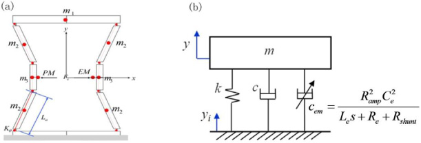
The schematic diagram of the hourglass-type electromagnetic isolator is shown as Fig. 1. The proposed isolator consists of an hourglass-type frame and an electromagnetic mechanism (Fig. 1(a)). The aluminum frame has characteristics of macro auxeticity and displacement amplification effect. Meanwhile, an electromagnetic mechanism consisted of electromagnetic and permanent magnets are fixed in the middle of the hourglass-type isolator. The coils are further connected to a NR shunt circuit with the impedance R shunt . Here the electromagnetic coils can be simplified as an independent voltage V e , an equivalent resistance R e and an inductance L e .

Schematic diagram of the isolator ((a) structural scheme; (b) NR shunt circuit; (c) motion relation).
Figure 1(c) shows the motion relation of the isolator. Frame deformation mainly concentrated in the eight flexible hinges. Considering the linear elastic deformation condition, the relationship between the input displacement of the mechanism (vertical direction) and the distance change of the electromagnetic mechanism (horizontal direction) can be written as
As shown in Fig. 2(a), the permanent magnet and the electromagnet are equivalent to a charged body with a uniform lateral current distribution [6]. For the a × b × c rectangular coil, let the coil turns and the applied current be N and I, then the current density of each lateral face is i = NI∕c Assuming that the a
′
× b
′
× c
′
rectangular permanent magnet is uniformly magnetized along the x-axis, the magnetization is
Since the permanent magnet is uniformly magnetized in the x-axis direction, the bulk and surface current density of the left and right surfaces are both zero, and only the outer four faces have an equivalent plane current. The force between the two energized conductors can be expressed as [7]

(a) diagram of the magnetic pair, (b) fit curve of C e .
The force between the magnetic pair (configuration of the permanent magnet and the electromagnet) can be obtained based on Eq. (4). Due to the symmetry of the structure, the forces in the y-axis and z-axis directions cancel each other out, leaving only the force along the x-axis. The total force F
sum
is
At the same time, when there is relative movement between the magnetic pair, an induced electromotive force is produced in the electromagnetic coils, and the relationship is
The shunt circuit technique is usually realized by connecting an electrical impedance to the terminals of a piezoelectric or electromagnetic transducer [8]. The energy of the transducer is consumed by the external circuit, thereby achieving vibration suppression.
In the proposed isolator, when there is a relative motion between the permanent magnet and the electromagnet, an induced current will be generated in the coils as well as the electromagnetic force between the magnetic pair, which will hinder the relative motion. The vibration isolation performance of the isolator will usually depend on the energy dissipation in the circuit, which is determined by the induced current in the circuit and the total equivalent impedance. However, as shown in Fig. 1(a), the NR shunt circuit connected with the electromagnet can increase the energy dissipation by canceling the inherent resistance of the coils. Further, it will achieve more effective vibration isolation. The NR circuit diagram is shown in Fig. 1(b) and the negative equivalent resistance can be written as
Because the isolator mainly consists of several rigid arms and eight flexible hinges, its kinetic model can be easily built by the pseudo rigid body model method (PRBM). Each flexible hinge can be seen as a pair of rotations with elastic restoring forces. It can be equivalently modeled by a rotating pair at the center of the flexible hinge and a torsion spring attached to the rotating pair. Howell et al. [9] gave the equivalent torsion spring stiffness Kθ of the pseudo-rigid model of the short arm flexible hinge.
The overall pseudo rigid body model is shown in Fig. 3(a). Figure 3(b) shows the active vibration isolation control model of the simplified vibration isolator. The total kinetic energy of the system is
(a) simplified pseudo rigid body model, (b) the single degree of freedom model.
The potential energy of the system mainly comes from the eight flexible hinges and can be written as
The generalized coordinate is defined as y = Δy. Then, the dynamic equation of the vibration isolation system can be obtained based on the Lagrange equation as follows.
The virtual work done by the main power is δW, and the generalized main power is obtained
Based on the Kirchhoff theory, the governing equation of the shunt circuit can be written as
As shown in Fig. 3(b), the relative velocity between the magnetic pair can be obtained as
Finally, the governing equation of this single degree of freedom system can be written as
Electromagnetic damping and transmissibility
Based on Eq. (19), the Laplace transform of the current can be driven as
Taking Eq. (20) into Eq. (15), the electromagnetic force can be derived as
As shown in Fig. 3(b), the electromagnetic force is equivalent to the electromagnetic shunt damping (c em ). Meanwhile, the electromagnetic shunt damping is the squared relation of the amplification ratio R amp , which means significant damping is acquired by leading the displacement amplification mechanism into traditional NR shunt damping system.
On the foundation of Eq. (15), (19) and (21), the transfer function of the isolator can be derived as
The parameters used in the simulation are given in Table 1. It is essential to select the NR value R shunt . For example, if R e + R shunt ≤0, the electromagnetic damping coefficient c em may be negative in Eq. (21). It can even cause c + c em <0, which means the system may be unstable.
Parameters of the hourglass-type electromagnetic isolator
Parameters of the hourglass-type electromagnetic isolator
To analyze the stability of systems and get the optimal NR value, the root locus diagram with the NR R shunt is given in Fig. 4(a). It can be seen that there is a wide stability range at point P (R shunt = −17.3 Ω). In other words, R shunt should have a specific scope [0, −17.3] to ensure the stability of the shunt circuit.

(a) Root locus diagram with R shunt , (b) transfer function curves of the isolator with different R shunt .
The transfer function curves of the isolator have been described as Fig. 4(b). Compared with the open-loop (R shunt = ∞) and closed-loop (R shunt = 0 Ω) conditions, the isolators with NR shunt impedance have a significant isolation performance. Notably, the amplitude of the resonant peak respectively drops by 39.03 dB and 26.53 dB when the NR selects the optimal value (R shunt = −17.3 Ω). The isolation effect at the optimal case is also obviously better than that at the non-optimal case (R shunt = −10 Ω).
Further three excitation conditions are considered, which are a half-sine pulse excitation, a sine resonance excitation and a random excitation with the frequency band of 50–70 Hz, respectively It is found in the simulation results that the current isolator has a significant isolation effect. From Fig. 5(a), the decay times are respectively 873.7 ms, 432.9 ms and 107.0 ms for the open-loop, the closed-loop and the optimal case where the decay time is defined as the time elapsed in response to attenuation to 20% of the initial amplitude. The optimal case can save 87.75% of decay time compared to the open-loop case. From Fig. 5(b), the stable amplitude for the optimal case decrease by 61.95% and 58.64% of those of the open-loop and the closed-loop, respectively. From Fig. 5(c), the root mean square (RMS) for the optimal case also declines by 70.90% and 55.17% of those of the other cases, respectively.
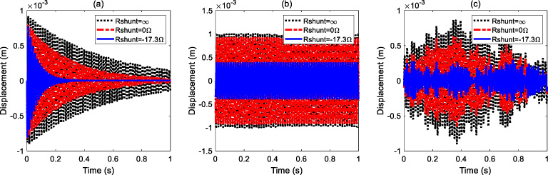
Displacement response of isolator. (a) half-cycle sine impulse excitation; (b) sine excitation; (c) random excitation.
An hourglass-type electromagnetic isolator with NR shunt circuit has been proposed. By the modeling and theoretical analysis of the isolator, it is found that its electromechanical coupling coefficient has a significant improvement via the design of the displacement amplification mechanism. The transfer function analysis and the vibration response simulation analysis results also fully demonstrate the excellent performance of the novel electromagnetic isolators. In the future, experimental studies will also be carried out to verify the isolation performance and optimize the parameters of the isolator.
Footnotes
Acknowledgements
This work is supported by the National Natural Science Foundation of China (Grant Nos. 11972024 and 11572240) and the Fundamental Research Funds for the Central Universities (Grant No. xzy012019058).