
Abstract
A micro-power-generator is developed with piezoelectric ceramics, which can convert the structural vibration energy generated by wind power into electricity to provide energy for micro-devices such as wireless sensor nodes. The vibration modes of the device are analyzed. The standard interface circuit for piezoelectric energy recovery and LTC3588-1 voltage stabilization circuit are selected, and the hardware circuit of the device is designed. The output voltage and power characteristics of micro-power-generator were analyzed under different loads, frequencies and amplitudes. The experimental results show that under the same wind speed, When the blunt body is a cuboid, the power generation effect of this device is the best under the optimal load, with the maximum output power of 350.7 μW. Under the same load with the same shape and structure, the load voltage and output power increase with the increase of wind speed.
Introduction
Wind energy has the advantages of sustainability, cleanliness and extensiveness. In the world, the use of wind energy is being widely developed [1]. Due to the large volume, high cost, and difficulty in operation and maintenance, traditional blade power generation system is difficult to integrate with small and independent electronic systems [2]. The micro-power-generator has become an electronic solution to micro-independent work such as wireless sensor nodes. It is an effective method of energy supply for system in outdoor work [3]. Because of the wider application prospect in the field of building and bridge detection, forest fire prevention and so on, it becomes the hot topic on the application of micro-electronic system through micro-wind power generation system [4–6].
Vortex-induced vibration is the phenomenon that when the air flow field passes through a non-streamlined blunt body, the air flow field will be blocked and changed, and periodically alternating vortices will occur on both sides of the blunt body behind. A wind-induced vibration piezoelectric wind power generation device combined with resonator design is proposed by ref. [6]. The self-excited vibration will be generated, when the wind blows into the resonator, and the vibration energy will be transformed into electric energy through the piezoelectric cantilever beam at the bottom of the resonator. A piezoelectric multi-directional wind-induced vibration power generation device proposed by Chongqing University can output electric energy in 2–17 m/s and work in different modes under different directions of wind [7]. Dressel University [8] proposes a piezoelectric current energy collector consisting of a cylindrical external extension piezoelectric cantilever. The maximum output power of the collector is 30 mW.
In this paper, a micro-power-generator was developed with piezoelectric bimorph. The vibration was induced by vortex, and the mechanical energy is converted into converted to electrical energy by piezoelectric bimorph. The wind energy is collected to provide energy for the outdoor work of small and independent electronic systems such as wireless sensor nodes. Experiments were performed to validate the micro-power-generator.
Principle and design of vortex-induced vibration generator
Principle of vortex-induced vibration generator
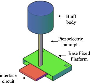
Structure of micro-power-generation device.
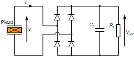
Standard interface circuit.
When a double-layer piezoelectric sheet bonded by a copper alloy substrate and a piezoelectric substrate bends under the combined action of wind and the top mass block, the voltage generated, the maximum output power and the electric energy generated per unit time can be expressed by the following calculation [9,10]:
The block diagram of the micro-power-generator is shown in Fig. 1. In the air flow environment, periodic force will be generated on blunt body, and the piezoelectric bimorph vibrate perpendicular to the wind direction. Due to the piezoelectric effect, the piezoelectric bimorph transforms vibration energy into electric energy. With suitable interface circuit, the energy can be harvested for load or other electric devices.
Compared with wind power generator, this is simpler and more compact, so it is easier to be miniaturized for small electronic devices. Without rotating parts, the cost of maintenance will be greatly reduced.
Circuit design of micro-power-generator without blades
In the experiment, the standard interface circuit is a full bridge rectifier circuit, which converts the AC power output from the positive piezoelectric effect transformed by the piezoelectric bimorph into DC power, and then generates a relatively stable voltage output through the regulated capacitor
Analysis of optimal load
For standard interface circuits, the charges flowing into the filter capacitor and the load is equal to the charges flowing out from both ends of the piezoelectric chip [10]. In the half cycle, the voltage only changes positive and negative, and the value does not change. Therefore, in the half cycle, the charge flowing into the filter capacitor is zero. As a result, it can be concluded that:
Simplify the above formula
Correspondingly, the available energy acquisition power is
Assuming that the excitation displacement assignment
In the constant vibration force, the energy of the whole system is equal to the sum of the energy consumed by the damper, and the energy recovered by the standard interface circuit.
According to the above analysis, the generated energy with standard interface circuit will increase first and then decreases with load. In practice, in order to achieve the highest efficiency of energy acquisition, it is necessary to select the load to achieve the best effect In this paper, an LTC3588-1 chip was chosen to work with standard interface circuit [11].
As shown in Fig. 3, experimental devices includes two parts: the micro-power generator and the measurement system. The wind generated by fan blow the air through blunt body, periodical force will vibrate the piezoelectric bimorph. The anemometer measures the wind speed in front of the blunt body, and the oscilloscope monitors the voltage at both ends of the load and process the data.
The diodes for standard interface circuit is 1N4007, and voltage regulated capacitor is 47 uF. Load was chosen an adjustable resistance of 1 MΩ. Circuit inductance L1 is 10 mH, storage capacitor Cs is 470 uF, and the wind speed measurement range is from 0.3 m/s to 30 m/s with accuracy of <5%. The piezoelectric bimorphs are QDA60-10-0.7, 60 mm in length, 10 mm in width, 0.7 mm in thickness and 50 mm in free length. The length, width and height of the cuboid blunt body are 29 mm, 29 mm and 59 mm respectively.The length, width and height of the cube blunt body are 29 mm, 29 mm and 30 mm respectively.The diameter and height of the blunt body of the cylinder are 30 mm and 29 mm respectively. Experiments were performed at the wind speeds of 14, 16, 18, 20 and 22 m/s respectively.
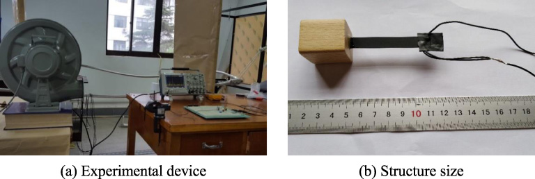
Experimental device physical map.
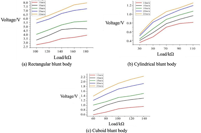
Load voltage for different blunt body with standard interface circuits at different wind speeds.
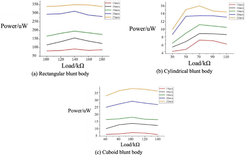
Output power of different blunt body devices at different wind speeds in a standard interface circuit.
Voltage and power of load with standard interface circuit
The piezoelectric bimorph was connected to the standard interface circuit. The voltage and output power under different blunt body are measured and compared. During the experiment, the resistance value of the adjustable resistance is changed to near the optimal load size of the device. With standard interface circuit, the voltage and power under different wind speeds and loads were analyzed in Fig. 4.
With the same blunt body and the same load, the output voltage of the micro-power-generator will increase with the wind speed. With same blunt body and the same wind speed, the output voltage at both ends of the load increases with load. In the same wind speed and load, the output voltage with rectangular body is larger than the other two, and the output voltage with cylindrical blunt body is the smallest.
It can be seen from Fig. 5, in the same blunt body and the same load, the output power increases with the wind speed, and reaches the maximum at 22 m/s. In the same blunt body and the same wind speed, the output power increases first and then decreases with load. The optimal load for different blunt body are 140 kΩ, 70 kΩ and 100 kΩ, respectively for Rectangular, cylindrical, cuboid blunt body type. This exponential result verifies the Eq. ((7)).
Output characteristics of micro-power-generator
To analyze the output characteristics of micro-power-generator, the piezoelectric bimorph was connected to the circuit designed with LTC3588-1. The input voltage and output voltage of the chip are recorded by an oscilloscope device in a certain period of time. With the different blunt body devices are tested with the wind speed of 14 m/s to 22 m/s. The relationship between the input voltage and the output voltage is shown in the Fig. 6.
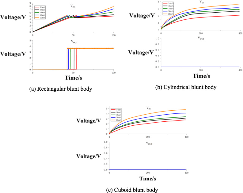
Input and output voltages of different devices through LTC3588-1 circuit under different wind speed.
For the Rectangular blunt body, the input voltage always increases in the beginning at all wind speeds, and achieve threshold of 5.13 V at 54 s, 51 s, 46 s, 44 s and 42 s, respectively. The output voltage step to the 3.6 V at the time that input larger than the threshold For the cylindrical and cuboid blunt body, the output voltage is always very small because the input cannot larger than threshold of 5.13 V.
Aiming at the demand of energy supply in outdoor work for micro-electronic systems such as wireless sensor nodes, a micro-power-generator developed with piezoelectric bimorph and blunt body. The output characteristics of different blunt bodies, different wind speeds and loads were analyzed with different circuit. The experimental results show that the generator with Rectangular blunt body achieves the highest output power on the optimal load, and the maximum output power is 350.7 uW. With the same load , the load voltage and output power increase with wind speed. It can provide energy for small and independent electronic systems such as wireless sensor nodes.
Footnotes
Acknowledgements
This is supported in part by National Natural Science Foundation of China (No. 51875277, 51607091).