
Abstract
In view of high temperature applications, c-axis oriented aluminium nitride films on aluminium substrate were produced by magnetron sputtering at low pressure (0.3 and 0.5 Pa) and different values of nitrogen concentration. XRD data show the highest intensity of (002) diffraction peak with nitrogen concentration of 0.4, and the peak value decreases when the nitrogen concentration moves away from 0.4. The transverse piezoelectric constant (absolute value) was determined for all conditions, the highest values observed with nitrogen concentration of 0.4 (in agreement with XRD data) and 0.8, with a slight preference for 0.4. These new experimental data and the presence of the two peaks of similar amplitude on the estimated transverse piezoelectric constant are useful information for the identification of good practical operative conditions for AlN films sputtered on aluminium, basic structure for the development of high temperature piezoelectric transducers.
Introduction
High temperature piezoelectric transducers are of interest in a wide range of applications, including aerospace and automotive fields, for in situ process monitoring of materials at high temperature [1,2]. Commercially produced lead zirconate titanate (PZT) based ceramics (PZT-4, PZT-5A and PZT-5H), well known and common piezoelectric materials, have a Curie temperature not exceeding about 350 °C [3]. C-axis oriented aluminium nitride (AlN), on the contrary, is a promising material for high temperature applications, owing to its very good physical and chemical stability and a rather broad operating frequency bandwidth when used as a film piezoelectric transducer. The adhesion of AlN film on aluminium substrate is very good, also at high temperature [2].
Magnetron sputtering is a well-known technique to obtain c-axis oriented AlN films, even if the nitrogen to argon ratio in the magnetron sputtering discharge is still a research issue. Low pressure is favorable for highly c-axis oriented AlN, but at low pressure, with different substrates, the best results were obtained at different values of nitrogen concentration [4]. In fact, full width at half maximum (FWHM) of the diffraction peak or of the rocking curve relative to the AlN (002) plane reported in literature in general show that, by varying nitrogen to argon ratio, a curve with a minimum (single optimum condition) is obtained, and the more you move from the optimal condition, the more the FWHM increases. The minimum of FWHM is obtained in a few cases with a low value of nitrogen concentration (e.g.: [5]), and in a few other cases with a high value of nitrogen concentration (e.g.: [6]).
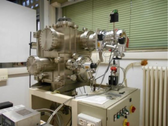
Magnetron sputtering experimental set-up.
We could not find in literature a clear indication of this optimum condition with aluminium as substrate; therefore, this case was investigated, assuming, in view to applications, as a reference property the AlN transverse piezoelectric constant. In this paper, AlN films were deposited on aluminium substrates by using the magnetron sputtering technique. Two sputtering low pressures were used, and at each pressure five values of nitrogen concentration were chosen. Film thickness was measured by using a surface profilometer and films were analyzed by XRD. AlN transverse piezoelectric constant e31 (C/m2) was estimated by building and testing a unimorph cantilever beam. AlN films realization and characterization are described in Section 2. A short discussion is given in Section 3 and then our conclusions are reported.
A magnetron sputtering system (Fig. 1) is in operation at the Department of Industrial Engineering of the University of Padova with a sputtering chamber of about 457 × 457 × 612 mm3 [7]. A 6” cathode is present, with an Al 99.99% target; target-substrate distance is about 6 cm. A DC-pulsed generator (Huettinger) was used as power supply: for all the operations reported in this work, it was set with a repetition frequency of 50 kHz and a duty cycle with 2 μs off. Sputtering chamber base vacuum was lower than 0.1 mPa.
Substrate
Commercial AISI 1050A aluminium was used. From a plate 2 mm thickness, thin parallepipedal pieces (70 × 12 × 2 mm3) were cut and used as substrates. Moreover, commercial soda-lime glasses (each one of 76 × 26 × 1 mm3) were used.
A preliminary smoothing of the surface of the parallelepipedal aluminium pieces where the film deposition is applied was performed by manual grinding, by means of abrasive papers of increasing fineness (P500, P1000, P2000, and P5000), each used for 10 minutes.
The surface roughness was significantly reduced. Figure 2 reports an example of comparison between initial and final roughness of the aluminium surface: the roughness rms value (obtained by using a KLA-Tencor P-16+ surface profilometer) was reduced from 0.6 μm to 0.15 μm.
The growth of AlN films was realized on three pieces for each operative condition. Two of them were parallelepipedal aluminium pieces and one was a soda-lime glass substrate. AlN film on one aluminium piece was used for the measurement of the transverse piezoelectric constant; AlN film on the soda-lime glass substrate was used for thickness determinations and mineralogical (XRD) analysis; the last one was for backup.
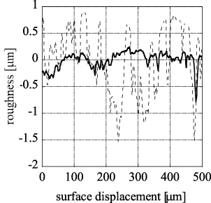
Example of roughness reduction of the surface of the commercial AISI 1050A aluminium before (dashed line) and after (continuous line) surface smoothing procedure.
The three substrates were partially masked by two auxiliary parallelepipedal aluminium pieces, 116 × 30 × 2 mm3 (with adhesive kapton tape used on the back of the structure for the fixing of the pieces) and the film deposition was carried out on one side, for a length of 40 mm, and the width of the substrate.
Two operative pressures were used: 0.3 Pa and 0.5 Pa. Argon and nitrogen gas flows were set by using for each gas a mass flow controller. The standard cubic centimeters per minute (sccm) of the two gases were set in order to have a total value of 25 sccm. At each pressure, five different mixtures of nitrogen and argon were used. By introducing the nitrogen concentration:

Thickness of AlN films deposited on soda-lime glass at low pressures: 0.3 Pa (empty circles) and 0.5 Pa (filled squares).
Each film was obtained with the following operative conditions: the power was set at 150 W and the time of the film grow was set at 20 hours.
The film thickness was measured on the soda-lime glass substrate, by a KLA-Tencor P-16+ surface profilometer. The measurement was performed in the central part of the film, either where a local film detachment had occurred or by using a diamond point stretching. In Fig. 3 we report the measured values obtained at 0.3 Pa (empty circles) and at 0.5 Pa (filled squares).
As expected, the deposition rate decreased with increasing nitrogen concentration [4]. Considering the average value of film thickness, that is about 12 μm, and the deposition time of 20 hours, an average deposition rate of approximately 10 nm/min was achieved.

XRD data at 0.3 Pa, nitrogen concentration of 0.4 (a), 0.6 (b), 0.8 (c), and 1 (d).
X-ray diffraction (XRD) analysis was performed using Bruker AXS D8 Advance diffractometer, set at 40 kV, 40 mA, in Bragg-Brentano configuration. The wavelength of the XRD radiation is 1.5406 Å (Cu K𝛼 radiation). Data were collected in a 2θ of 18°–70°. XRD data of AlN films on soda-lime glass substrate were collected for all processing conditions, except the case of N2 concentration equal to 0.2, according to which, by visual inspection, the film was very irregular. In all measurements (pressure: 0.3 Pa and 0.5 Pa, and at each pressure value, N2 concentration: 0.4, 0.6, 0.8, and 1) one sharp peak was clearly detected at 2θ ∼ 36°, corresponding to (002) plane. In Fig. 4, four cases corresponding to the applied pressure of 0.3 Pa are depicted. Same cases for 0.5 Pa led to similar patterns. AlN films, with a very good orientation of c-axis, were obtained in all conditions. The highest value of the intensity of the (002) peak, at both pressures, was achieved applying a N2 concentration of 0.4.
Transverse piezoelectric constant
In order to obtain the AlN transverse piezoelectric constant, a unimorph cantilever beam was built.
The first electrode of the beam configuration is the aluminium parallelepipedal piece 76 × 12 × 2 mm3 previously introduced. Over it, there is the piezoelectric AlN film on a 40 × 12 mm2 area deposited with the magnetron sputtering technique, as already indicated. Then, in air, on the side where the AlN film was deposited, an insulating tape (20 μm total thickness) is placed on the whole surface 76 × 12 mm2. Over the insulating plate, on the area where the AlN film is present, by using a silver conductive paint, the second electrode is made. A mask of adhesive paper tape is used in order to identify the painting area, and after the painting is removed.
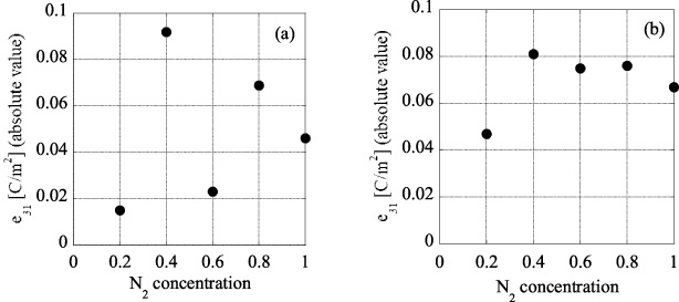
Transverse piezoelectric constant e31 (absolute value) at p = 0.3 Pa (a) and at p = 0.5 Pa (b).
A copper tape, with conductive glue, is used as extension of the second electrode, placed near to the painted area and put in electrical contact with it by additional silver conductive paint. Where the joint of the unimorph beam is made, a further insulation is performed by pieces of adhesive paper tape and an insulating washer; finally two wires, welded on metal eyelets were connected to the aluminium substrate and the copper tape, by using an insulating nut and screw. The presence of the insulating tape between the AlN and the second electrode ensures that the silver paint does not enter into the AlN, avoiding a short-circuit between the two electrodes.
An electrodynamic shaker 2007E of the Modal Shop Inc. is used for testing the electromechanical performances of the cantilever. The shaker is driven by a proper signal generator connected to a power amplifier, in order to impose the acceleration value, that is measured by an accelerometer, mounted at the joint of the cantilever beam. The output voltage rms values at different frequencies are recorded. Considering a single degree of freedom (SDOF) model, neglecting air damping and the rotation of the base of the cantilever [8], from the data fit of the output voltage (rms value) of the piezoelectric cantilever at different frequencies, the capacitance of the AlN film was obtained [9].
The absolute value of the transverse piezoelectric constant was derived, considering a parallel plates capacitor configuration, from the measured value of the film thickness, assuming an AlN relative permittivity of 9 [10]. In Fig. 5 the obtained values of e31 (absolute value) are reported. It can be seen that two peaks are present, at N2 concentration of 0.4 and 0.8 respectively. The highest value of e31 (absolute value) is about 0.09 C/m2, at p = 0.3 Pa, with N2 concentration of 0.4.
C-axis well oriented AlN films were obtained, as shown by XRD data. The highest intensity of the distinctive diffraction peak was detected at N2 concentration of 0.4, for a pressure of 0.3 and 0.5 Pa. These data are in agreement with a single optimum condition at a low N2 concentration of 0.4 [4].
The estimation of the AlN transverse piezoelectric constant e31 (C/m2) gave two local peaks: one at N2 concentration of 0.4 in agreement with the XRD data and a second one at N2 concentration of 0.8. This is a new aspect.
From literature, the XRD data in general show a single optimum condition and the more you move from the optimal condition, the worst it is. There is no general agreement about the optimum condition, as N2 concentration of about 0.4 and 0.8 are both good candidates [4–6]. Two mechanisms are proposed in literature, one for lower N2 concentration (related to the creation of the AlN atomic bondings) and one for higher N2 concentrations (related to the assembly of the closed-pack (002) plane) [4]. In this paper XRD data indicate an optimum condition for N2 concentration of 0.4, but it can be noticed that the AlN transverse piezoelectric constant e31 (absolute value) presents two local peaks and not only one, with the second local peak not so lower than the highest one.
Conclusion
New data relative to AlN deposited by magnetron sputtering on aluminium substrate are reported. These data are important in view to high temperature applications.
The XRD data of AlN deposited on aluminium by DC pulsed magnetron sputtering at 0.3 and 0.5 Pa indicate an optimum value with N2 concentration set at 0.4. In the meanwhile, deriving also the resulting transverse piezoelectric constant e31, two local peaks resulted varying the N2 concentration. The highest value was found for N2 concentration of 0.4, in agreement with the XRD data, and the second one was identified at 0.8, with an absolute value of e31 slightly lower than the one identified at 0.4.