
Abstract
In this paper, the conventional database type fast forward solver for efficient simulation of eddy current testing (ECT) signals is upgraded by using an advanced multi-media finite element (MME) at the crack edge for treating inversion of complex shaped crack. Because the analysis domain is limited at the crack region, the fast forward solver can significantly improve the numerical accuracy and efficiency once the coefficient matrices of the MME can be properly calculated. Instead of the Gauss point classification, a new scheme to calculate the coefficient matrix of the MME is proposed and implemented to upgrade the ECT fast forward solver. To verify its efficiency and the feasibility for reconstruction of complex shaped crack, several cracks were reconstructed through inverse analysis using the new MME scheme. The numerical results proved that the upgraded fast forward solver can give better accuracy for simulating ECT signals, and consequently gives better crack profile reconstruction.
Introduction
Eddy current testing (ECT) is one of the major nondestructive testing and evaluation (NDT&E) techniques. Because of its features of high detection speed, non-contact, real-time inspection and high sensitivity for surface/near surface defect, ECT is being applied in many industrial fields, such as the nuclear power plant and aerospace engineering [1–6]. The quantitative evaluation of crack and material feature parameters using ECT signals, e.g., crack length, crack depth, wall thickness, conductivity etc. plays a very important role for safety assessment and efficient maintenance of key engineering structures. Sizing these defect parameters using the calibration curve constructed with use of artificial specimens is often adopted in practice [7,8]. The calibration strategy, however, has limitation as it is low accuracy and unsuitable for quantitative evaluation of multiple parameters. Crack sizing through inversion of measured ECT signals gives a good solution for better results. For crack reconstruction based on ECT, a rapid scheme using the A-𝜙 formulation was developed by authors for efficient prediction of ECT signals, and its validity was proved through numerical simulations and experiments [9–11]. To reconstruct a crack of complicated shape, concept of MME was introduced and implemented in the fast forward solver to treat crack of complicated shape with a regular finite element mesh. A Gauss point classification strategy was used for the calculation of element coefficient matrix of the MME [4], which however has less precision if the crack zone in the MME is relative small.
In this paper, the conventional ECT fast forward solver of database approach is upgraded by using an new MME scheme for better crack sizing from ECT signals. During the crack reconstruction, the crack zone in an MME is subdivided into several hexahedron elements (hereafter, crack sub-elements) of crack conductivity, and the element coefficient matrix of the MME is calculated based on those of the sub-elements. In practice, a transformation matrix is introduced to cope with the shape function difference between the crack sub-element and the MME. Finally, the merits of the upgraded fast forward solver are demonstrated through comparing the forward and inverse simulation results obtained with and without using the new MME scheme.
Basic theory for crack reconstruction with database type fast forward solver
ECT inversion and fast forward scheme
The inverse problem to reconstruct crack profile from ECT signals is usually treated as an optimization problem to minimize the mean-square residual error between the measured ECT signals and the simulated ones due to a crack of predicted profile with use of the fast forward solver. In practice, the objective function of this optimization problem is usually defined as [12].
In the conventional numerical simulation method, ECT signals are calculated by using the full FEM-BEM hybrid code of A-𝜙 formulation. The discretized system of linear equations of A-𝜙 formulae for solving magnetic potential perturbation due to a flaw is as follows [9]
The validity of the conventional database type fast forward solver and the corresponding inversion scheme are proved through crack reconstruction using both simulated and measured ECT signals [11]. As the unflawed potential databases are necessary to be established a priori with a regular mesh, the multi-media element approach, i.e. to use finite element with both base material and crack, has been proposed by the authors to treat cracks of complicated shape with use of the above database type fast forward solver [4]. The element coefficient matrix of MME was calculated by an updated Gauss integration method by classifying and summing up the values at the Gauss points in crack zone (here after, Gauss point classification method). However, when the crack zone in the MME is relative small, the Gauss point classification method cannot give satisfactory accuracy for coefficient matrices as the number of the Gauss points cannot be too high. Authors have proposed an advanced MME scheme to calculate the coefficient matrix for narrow crack in a wide MME [13]. In this work, this advance MME algorithm is upgraded and applied to the fast forward solver for reconstruction of cracks of constant width but of complicated crack tip profile.
New forward scheme using advanced MME
Principle of the advanced MME scheme
During ECT inversion using the database type fast forward solver, the reconstructed crack of complicated shape usually cannot be exactly discretized with use of the regular mesh utilizedfor the database establishments. The coefficient matrix of MME introduced by authors to treat this problem was approximately calculated with use of the Gauss point classification strategy [4]. However, the strategy is not suitable in case that the volume fraction of the crack zone in the MME is relative small, which may occurs frequently during the crack reconstruction. In the follows, a new algorithm for calculating coefficient matrix of the MME is proposed aiming to solve this problem [11].

Mesh and element of advanced MME.
As shown in Fig. 1, when the crack tip line (crack edge) of a constant width crack is approximated by piecewise line segments, MME such as that shown in Fig. 1(b) may appear at crack edge if the suspicion rectangular crack region was subdivide into a regular mesh of cuboid element of width equal to the crack width as shown in Fig. 1(a). In this case, the MME can be subdivided into several triangular prism sub-regions of number related to the piecewise points in the element as shown in Fig. 1(b), and the FEM coefficient matrix of the full MME becomes a summation of integrations on each sub-regions as σ0 −σ(
In this way, the coefficient matrix of the MME can be calculated with use of Eq. (6) by simply summing up the coefficient matrices of each triangle prism FEM elements that can be calculated by using the Gauss integration method easily. For detailed derivations of formulae above, one can refer to [13].
Based on the formulae above, the database type fast forward solver of authors for ECT inversion was upgraded. To confirm the validity of the new fast forward solver code, the ECT signals of a pancake coil over an Inconel steel plate of 1.25 mm thickness and 1.0 MS/m conductivity were simulated by using the original full FEM-BEM hybrid code, the conventional fast forward solver and the new fast forward codes respectively. The pancake coil is of 3.2 mm outer diameter, 1.2 inner diameter and 0.8 mm thickness and of 100 number of turns. The driving current in the coil is 1 A and 300 kHz frequency. The probe is scanned along the crack from −8 mm to 8 mm with a 1 mm pitch and 0.5 mm liftoff. The ECT signals of 3 inner cracks of profile shown in Table 1 were calculated and compared. As regular mesh to establish the database is of 16 × 5 cuboid element of 1 mm length, 0.2 mm width and 0.25 mm depth, all the cracks cannot be exactly discretized with the regular mesh.
Parameters of the simulated cracks
Parameters of the simulated cracks
The FEM mesh for the full FEM-BEM method is taken as one just fitting the crack shapes as shown in Figs 2(a), 4(a) and 6(a), while uniform meshes including some MMEs containing crack edge are adopted for both the conventional and upgraded fast forward codes as shown in Figs 2(b), 4(b) and 6(b).
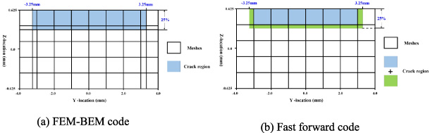
FEM mesh for crack No.1 (6.5 mm, ID25%)
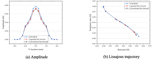
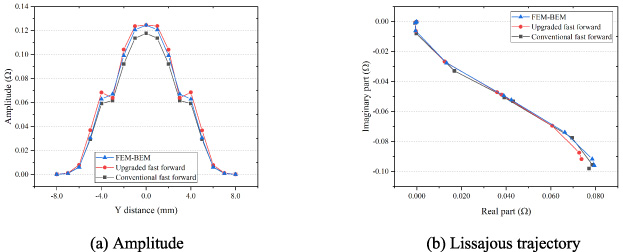
Comparison of simulated signals for crack No.1.
The impedance signals simulated with the fast forward solvers are compared with those of the full FEM-BEM code in the Fig. 3, Fig. 5 and Fig. 7 respectively for the cracks of profile shown in Table 1. One can find that all the signal amplitudes and the signal phase of the results of the new fast forward solver are closer to those of the full FEM-BEM code compared with the results of the conventional fast forward solver, i.e., the fast forward solver using new MME scheme is of higher precision than that using the Gauss point classification scheme.
As for the simulation time, the full FEM-BEM code needs 181.25 s while the fast solvers need 1.56 × 10⁻² s and 1.56 × 10⁻² s for the Gauss point classification method and the new MME scheme in a normal PC. Both the two fast forward codes are much faster than the full FEM-BEM code. Meanwhile, the simulation times of the two fast solvers are the same in this paper.
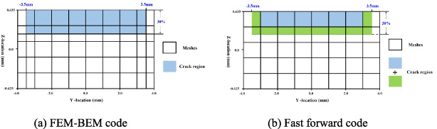
FEM Mesh for crack No.2 (7.0 mm, ID30%).
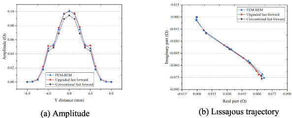
Comparison of simulated signals for crack No.2.

FEM Mesh for crack No.3 (7.5 mm, ID35%).
Comparison of simulated signals for crack No.3.

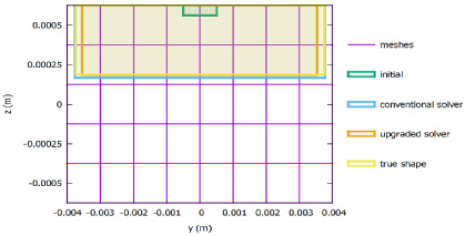
Reconstruction result for crack No.1.
To show the efficiency of the new forward solver for crack reconstruction from ECT signals, simulated crack signals obtained with use of the full FEM-BEM code for the 3 cracks shown in Table 1 are taken as the input ECT signals to reconstruct their crack profile by using the CG inversion algorithm developed by authors in [11] and the conventional or new fast forward solvers respectively. For all the 3 cases, small crack of 1.0 mm long and 5% relative depth was taken as the initial guess of crack profile. For simple, the target crack was supposed of rectangular shape and of 0.2 mm constant width, i.e., the cracks are supposed of rectangular shape and only their depth and length are taken as unknowns to be reconstructed. In fact, the rectangular crack model is enough to demonstrate the efficiency of the new MME scheme in view that the most typical situations of MME can be covered with this simple crack model, e.g. the MMEs in the corner of the crack. In addition, a mesh of 16 × 5 cells was adopted to establish the databases for the fast forward solver and for a suspicion crack region of 8 mm long and 1.25 mm depth located in the center of the plate. The crack width was set as 0.2 mm and treated as fixed value. In crack reconstruction, both the real and imaginary signals at 17 scanning points are taken as input data, and all the weight coefficients were taken as 1.0. For termination of the inversion procedure, a minimum error value of 2.5 × 10⁻⁴ or a maximum iteration number of 1000 were selected.
As reconstruction results of the 3 selected cracks, the reconstructed crack shape with both the conventional and the new fast forward solver are shown in Fig. 8 to Fig. 10 with comparison with the true crack shape and the initial guess. Both the crack profiles reconstructed with the conventional and new MME scheme are quite near the true crack values but the results of the new fast forward solver are in better agreement with the true crack profile, which proves the validity of the new MME scheme for the inverse problem to predict crack size.

Reconstruction result for crack No.2.
Reconstruction result for crack No.3.
To compare the detailed numerical error of all the inversion results, the values of the true crack depth, the values of the reconstructed crack depth with both the conventional MME scheme and the new MME scheme are given in Table 2. These detailed results depict clearly that the reconstruction error using the upgraded fast forward solver is relative smaller than those using the conventional solver for all the 3 inversion examples. The simulation times of the two fast solvers are about the same for all the cases.
Comparison of reconstruction results
Based on the numerical results of both the forward and inverse analysis, it can be concluded that the new fast forward solver using the advanced MME scheme is more feasible for reconstruction of crack even with a give regular mesh.
An upgraded fast forward solver is developed and validated in this paper based on a new MME scheme to treat crack of complicated shape with a regular FEM mesh. Instead of the Gauss point classification, a new scheme to calculate the coefficient matrix of the MME is proposed and implemented in the fast forward solver to improve the precision of the element coefficient matrix. Numerical results of both forward and inverse analyses reveal that the upgraded fast forward solver can give better accuracy in simulation of ECT signals due to a crack of complicated shape, and consequently can give better prediction of crack profile based on the ECT signals.
Footnotes
Acknowledgement
This work was supported in part by the National Key Research and Development Program of China under Grant 2017YFF0209703 and the National Science Foundation of China under Grant 11927801.