
Abstract
Ultra-low frequency mechanical excitations are omnipresent in our surrounding environment, but the efficient exploitation of them is generally difficult because they normally drive the widely reported cantilevered harvesters to work under non-resonant conditions. Although the frequency up-conversion strategy has been proposed to mitigate this issue, it usually leads to complicated structures. This paper reports a novel energy harvesting approach based on the twisting vibration of a string-driven rotor. To examine the feasibility of this approach, an electromagnetic energy harvester is designed, which is composed of a lid, a rotor with embedded magnets, a pendant, and a tube with pick-up coils attached to the outer surface. The rotor is suspended between the lid and the pendant through a piece of string, and then actuated by the ambient excitations through the string. Under the excitations produced by a crank-slider mechanism, the designed harvester can generate useful electric outputs that are proportional to the excitation amplitude, the initial angle between the pendant and lid, and the excitation frequency. Moreover, the harvester can also provide 0.034 mW power when it is periodically pulled by the human hand at approximately 1 Hz. This study demonstrates the potential application of the string-driven rotor in collecting energy from ultra-low frequency excitations.
Introduction
The ultra-low frequency mechanical energy is abundant and comes in diverse forms (such as ocean wave motions, vehicle vibrations human activities, and earthquakes [1–3]). The technology of generating electricity from the ultra-low frequency mechanical energy thus provides a desirable solution for implementing self-sufficient wireless sensor networks, internet of things, portable and even wearable electronics [4–6]. The conversion from the mechanical energy into electric energy can be achieved through various mechanisms, including piezoelectric effect [7], electromagnetic induction [8,9], electrostatic induction [10], and triboelectric effect [11].
Although the ultra-low frequency mechanical energy is ubiquitous in the surrounding environment, the efficient exploitation of it is generally difficult because the widely studied cantilevered harvesters normally have relatively high resonant frequencies. This issue has attracted increasing attention in recent years. Wu et al. [12] devised a piezoelectric spring pendulum harvester using binder clip structure, which generates 13.29 mW output power at 2.03 Hz. Yang and Cao [13] reported a tristable hybrid vibration energy harvester, which achieves the enhanced energy harvesting performance over a wide bandwidth. Fan et al. [14] proposed a monostable piezoelectric energy harvesting strategy to shift the operating frequency band toward the lower frequency. Fan et al. [4] also drafted an electromagnetic energy harvester with two-degree-offreedom (2-DOF) configuration to capture energy from some ultra-low frequency motions. Pillatsch et al. [15] proposed to exploit the ultra-low frequency mechanical motions by converting them to high-frequency vibrations of an array of piezoelectric cantilever beams.
Compared with the aforementioned vibratory energy harvesters (VEHs), the energy harvesters for rotation motions have also gained increasing research attention in recent years. The reported harvesters for rotation motions can be classified into two groups. The first group is designed based on the cantilever beams that are driven to vibrate and generate electricity by fixing it in a rotating environment. For example, Wang et al. [16] proposed a weighted-pendulum-type electromagnetic generator for collecting energy from the rotational wheels, and the natural frequency of the generator can be adjusted to match the rotational speed of the wheel. Cooley et al. [17] investigated the performances of typical piezoelectric and electromagnetic harvesters when subjected to the rotation with constant angular speeds. Roundy and Tola [18] reported a piezoelectric energy harvester to capture energy from the rotating wheel, in which a large steel ball is employed to trigger the vibration of two piezoelectric beams. The operation of the second group, called the rotational energy harvester (REHs), depends on a fixed stator and a freestanding rotor. Typical REHs include the electromagnetic REH developed by Halim et al. [19], in which springs are used to improve the REH performance. Experimental results showed that the prototype generated the maximum average power (61.3 μW) when the rotational amplitude and frequency are 25° and 1 Hz, respectively, which is about 6 times higher than that produced by its unsprung counterpart. To scavenge energy from low-frequency (<10 Hz) and irregular human motion, Liu et al. [20] proposed an electromagnetic REH with non-resonant operating capability. At 8 Hz, the electromagnetic REH can deliver a maximum power of 10.4 mW to a load resistance of 100 Ω.
This paper reports a twisting vibration energy harvester (TVEH) to scavenge energy from ultra-low frequency mechanical vibrations. Based on the electromagnetic induction, the designed TVEH contains a piece of string, a lid, a disk-shaped rotor, a pendant, a tube with four sets of coils. Distinguishing from the existing REHs that use a bearing structure or a shaft to support the rotor, the designed harvester utilizes just a string to support the rotor and in the meanwhile transfer external excitations to the rotor, featuring a very simple structure. Experimental studies are performed to examine the voltage and power outputs of the TVEH under various conditions. In addition, the performance of the TVEH is also explored when it is pulled by human hand.
Operational principle
The schematic diagram of the TVEH is illustrated in Fig. 1(a). The TVEH is comprised of a piece of string, a lid, a tube, four sets of coils, a pendant and a disk-shaped rotor with four radially-arrayed magnets. For the lid, rotor and pendant each of them is machined with two symmetrical holes, through which the rotor is suspended between the lid and the pendant via the string that loops through the six holes anticlockwise (1 →2 →3 →4 →5 → 6 →1) or clockwise (1 →6 →5 →4 →3 →2 →1). The four sets of coils are radially arranged around the outer surface of the tube, and they are connected in series for achieving a high output voltage. Two copper balls are embedded in the pendant and slide along the two grooves of the inner wall of the tube, which guarantees the z-directional motion of the pendant.
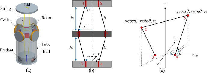
(a) Schematic of TVEH; (b) string-suspended rotor; and (c) geometrical relationship between rotor and pendant.
The string-suspended rotor is shown in Fig. 1(b), where r1 is the half of the span between the two holes in the lid, and r0 and r2 have similar denotation. The initial gap between the lid and the rotor is h1, and the initial distance between the rotor and the pendant is h2. As shown in Fig. 1(c), take the geometrical relationship between the rotor and the pendant for example, the initial length of the string between hole 4 and hole 5 is
To start the twisting vibration (small-angle rotation) of the rotor, an initial rotation angle between the lid and the pendant is required, which gives rise to the initial torque acting on the rotor. The initial toque acting on the rotor by the twisted sting generates the initial potential energy stored in the system, which can be released to actuate the rotor to rotate under the z-directional excitation. The rotation of the rotor will also lead to the twisted string and then potential energy stored in the system. Therefore, the interconversion between the system’s potential energy and the kinetic energy of the rotor can be sustained under the z-directional repeated excitations. The electricity can then be generated based on the exploitation of the relative motion between the rotor and a stator through the electromagnetic induction.
The as-fabricated TVEH prototype is shown in Fig. 2. The lid, rotor, tube, and the pendant are made of UV Curable Resin through a 3D printer. The four magnets (Nd–Fe–B–N42) embedded in the rotor have the same size, and the four sets each with 200 turns are made of varnished wire. The string is made of polyester with a radius of 0.3 mm and the wall thickness of the tube is 1.5 mm. The dimensions of the prototype are given in Table 1.
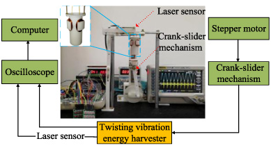
Experimental setup and prototype.
Structural parameters of the prototype
In order to generate the periodic mechanical excitations, a crank-slider mechanism is devised to provide the external excitation. The crank-slider mechanism is driven by a stepper rotor and controlled by a single-chip microcomputer. The motion frequency of the slider can be adjusted by changing the rotation speed of the stepper rotor and the motion amplitude is dependent on the eccentric position of the connection rod on the driving wheel. In addition, it should be noted that the maximum displacement of the slider is the diameter of the driving wheel. The position and frequency of the pendant are measured using a laser sensor (HL-C203BE), and the TVEH response is displayed and recorded by an oscilloscope (Rigol DS1074). The schematic of block diagram of the experiment setup is also shown in Fig. 2.
Throughout the experimental study, h1, h2, r0 and r2 are kept at 35.5 mm, 35.5 mm, 8.5 mm and 3 mm, respectively. The output power is calculated according to P = VRMS2∕R CL , where VRMS is the root-mean-square (RMS) value of the voltage across the load R CL . In order to achieve the optimal power output, a resistor of 66 Ω, which is equal to the coil resistance, is used in the experimental test.
Under various pull amplitudes, the RMS open-circuit voltage and the power output are displayed in Fig. 3(a) and (b), respectively. It is obvious that both the voltage output and the power output increase with an increase in the pull amplitude. This observation may be due to the fact the mechanical energy fed into the harvester increases as the pull amplitude is enlarged, which contributes to the improvement in the electric outputs. Moreover, another observable general trend is that the voltage and power outputs rise as the excitation frequency varies from 1 Hz to 4 Hz.

(a) RMS open-circuit voltage output and (b) power output under various pull amplitudes.
However, an unexpected drop in the electric outputs happens at 2 Hz, which may be caused by the phase mismatch between the z-directional linear reciprocating motion of the rotor induced by its rotation and the z-directional excitation. The TVEH can be considered as a 2-DOF system with the rotor and lid constituting the first DOF and the rotor and pendant forming the second DOF. The electric outputs thus crest at two frequencies (1.5 Hz and a frequency higher than 4 Hz) and dip somewhere (2 Hz) between the two frequencies. In addition, the z-directional excitation can drive the rotor to do small-angle twisting vibration with frequencies higher than the excitation frequency, up-converting the excitation frequency and then improving the functionality of the harvester, as shown in the insets of Fig. 3. When the harvester is excited at 4 Hz, the voltage and power reach their maximum values, which are 0.13 V and 0.097 mW, respectively. It should be mentioned that the devised crank-slider mechanism has a maximum frequency of 4 Hz, and thus the experimental test with higher excitation frequency is not conducted. However, it can be expected that the electric outputs will continue to grow with a small increase in the excitation frequency.
Under various initial angles between the lid and the pendant, the voltage output and the power output as a function of the excitation frequency are plotted in Fig. 4(a) and (b), respectively. It is observable that the electric outputs of the TVEH increase as the initial angle varies from 60° to 120° because a large initial angle can result in more potential energy initially stored in the system. Hence, more mechanical energy can be converted from the initial potential energy, contributing to the improved electric outputs. Due to the same reason as discussed above, the electric outputs jump down at 2 Hz. For this experimental study, the voltage and power outputs of the TVEH are maximized at 4 Hz, which are 0.1 V and 0.052 mW, respectively. In addition, the time-domain voltage outputs given in the insets of Fig. 4 also demonstrate the frequency up-conversion mechanism achieved by the TVEH.

(a) RMS open-circuit voltage output and (b) RMS power output under various initial angles.

(a) RMS open-circuit voltage output and (b) RMS power output under various spans between the two holes in the lid.
As shown in the second section, the operation of the TVEH depends on the initial torque acting on the rotor, which is generated by rotating the lid a small angle with respect to the pendant in this study. Experiments have revealed that the initial torque acting on the rotor by the lid is affected by the span (d1 = 2r1) between the two holes in the lid, which in turn influences the voltage and power outputs, as shown in Fig. 5, in which the initial angle and the pull amplitudes remain at 60° and 24 mm, respectively. It is evident that both the voltage output and the power output decrease with an increase in the value of d1. Although a large value of d1 can bring about a large torque acting on the rotor, an enlarged torque can also restrain the rotation of the rotor if the rotation angle opposes the initial angle in terms of rotation direction. Consequently, for a large value of d1, the rotation of the rotor is confined within a small angle although the motion of the rotor can be started easily. Due to the nonlinear and quasi-2-DOF features of the TVEH, changing the span of the two holes in the lid leads to the variation of the nonlinear stiffness, which brings about the shift of the dip in the electric outputs owing to the complicated interaction between the two subsystems.
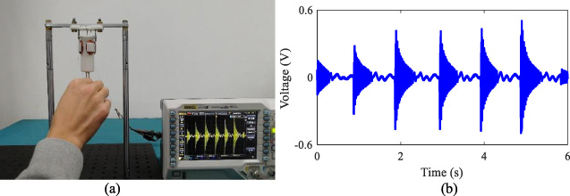
(a) Driving the manufactured prototype by hand and (b) open-circuit voltage waveform.
To examine the feasibility of the TVEH in harnessing energy from human body motions, the fabricated prototype is also fixed to a frame and then pulled by a human hand, as shown in Fig. 6(a). In this test, the value of d1 is kept at 12 mm and the initial angle between the lid and the pendant is fixed at 60°. The hand excites the TVEH at a frequency of approximately 1 Hz, and the generated voltage waveform is pictured in Fig. 6(b). Each time the harvester is pulled by hand, the output voltage peaks and then attenuates with time. The RMS open-circuit voltage and the average power under this operation are 0.1 V and 0.034 mW, respectively, demonstrating the potential application of the TVEH in converting human body motions into electricity.
It should be noted that the excitation frequency is limited within 4 Hz in this study. For higher excitation frequency, the rotor may rotate with large angles (>180°) and high speeds. In this case, the preliminary experiments have shown that the output voltage can be higher than 3 V and the output power may reach 30 mW. The performance of the proposed harvester with excitation frequency higher than 4 Hz will be systemically examined with an improved experimental setup. This work is currently in progress and will be reported in a separate paper.
In this paper, an electromagnetic energy harvester is realized based on the twisting vibration of a string-driven rotor. The proposed harvester consists of a lid, a rotor with four embedded magnets, a pendant, and four sets of coils attached to a tube. When excited by a crank-slider mechanism, the proposed harvester exhibits the voltage and power outputs that increase with an increase in the excitation amplitude, the initial angle between the lid and the pendant, and the excitation frequency (from 2 Hz to 4 Hz). The experiments also demonstrate that the proposed harvester can convert the ultra-low excitation frequency to the higher frequency twisting vibration of the rotor. In addition, useful electric outputs can also be generated by the proposed harvester when it is excited by the human hand. This study demonstrates the potential applications of the string-driven rotor in capturing energy from ultra-low frequency mechanical motions.