
Abstract
In this study, a magnetic resonance wireless power transmission system with a sown auxiliary coil is described. The system is proposed to deliver power to an “implantable cardioverter defibrillator” (ICD) device from a bed. The auxiliary coil is supposed to be sown in a shirt. With the coil, the poor coupling coefficient and the effective quality factor can be improved. In this study, the power efficiency was investigated on a magnetic resonance wireless power transmission system with a sown auxiliary coil by using a 1/2 scaled model. As a result, when transfer distance was 100 mm (200 mm in the full scaled model) and lord resistance was 20 Ω, the maximum transfer efficiency with an auxiliary coil was measured to be about 70% much higher than without that.
Introduction
Recently, a lot of magnetic resonance wireless power transfer systems are reported [1–3]. Wireless power transfer can be used to charge a battery in an implantable device such as an “implantable cardioverter defibrillator” (ICD) [4,5]. Such a device does not necessarily have to be charged continuously. It is, therefore, convenient that the battery is charged from the bed during the patient was laying. The ICD device is often set under the skin near the chest of the patient. The distance between the receiver and the transmitter set in the bed can be 200 mm or more. The diameter of the receiver coil will be less than several cm. The coupling coefficient between the coils can be very small. The power efficiency, therefore, will be significantly reduced. The power efficiency can be improved by setting an auxiliary coil near the receiver one [6]. The auxiliary coil can be set on a cloth such as a shirt. The coil on cloth should be sufficiently flexible for comfortability of the patient. We proposed coils which can be sown to cloth [7,8]. The coils were manufactured with litz wire. The sown coil is suitable as the auxiliary one because the coil sown on cloth is sufficiently flexible to fit the shape to the body of the patient. Moreover, the auxiliary circuit composed of only an auxiliary coil and a capacitor will have a high quality factor and the total power efficiency can be improved.
In this paper, a wireless power transmission system with an auxiliary sown coil for supplying power to a patient laying in a bed is proposed. A schematic diagram of the wireless power transmission system with a sown auxiliary coil was shown in Fig. 1.
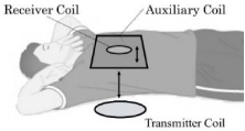
Schematic drawing of a wireless power transmission system with a sown auxiliary coil.
In this study, 3 coils for wireless power transmission were used. These coils are a transmitter one supposed to be set in a bed, a receiver coil installed in an implantable device and an auxiliary coil sown on cloth. The size of the receiver coil should be small to be installed in the implantable device. In this study, the diameter of the receiver coil will be assumed to be 40 mm to be installed into an ICD whose size is approximately 50 mm × 50 mm. The size of the auxiliary coil should be smaller than that of a shirt. Hence, the size of the auxiliary coil was assumed less than 300 mm. The coupling coefficient k1a between a transmitter coil and an auxiliary coil will be increased as the size of the coils for the large transfer distance, while the coupling coefficient k2a between the receiver coil and a large auxiliary one will be decreased as the size of the auxiliary one. In this study, as a first step, the size of the transmitter coil was designed so as to obtain a maximal value for the product of k1a and k2a. The square-like shape was chosen for the auxiliary coil because it was easy to be sown. The shape of the other coils was circular spiral.

Configuration of the coils in the simulation to calculate the coupling coefficients.
The coupling coefficients were calculated with a simulation software (Fast Field Solvers). The configuration of the coils in the simulation was shown in Fig. 2. All coils were aligned on the central axis. The distance between the receiver coil and the auxiliary one was set to be 10 mm. The distance between the transmitter coil and the auxiliary one was set to be 200 mm. The coupling coefficient products of k1a and k2a calculated varying the diameter of the transmitter coil was shown in Table 1 for the auxiliary coil with the side length up to 300 mm. The maximum product was obtained for 700 mm-diameter of the transmitter coil and for the side length of the auxiliary one. Therefore, an optimal diameter of the transmitter, the side length of the auxiliary, and the diameter of the receiver were determined to be 700 mm, 300 mm and 40 mm, respectively.
The coupling coefficient products of k1a and k2a
Some parameters of the coils are scaled
In this study, as a first step to investigate the improvement of the efficiency due to the auxiliary coil in experiments, the coils were fabricated with half of the sizes described in Section 2. In this session, the electric characteristics of the coils are described. The scaling factor was determined so as to keep the Q factor to the original [9]. Some parameters of the coils are scaled as shown in Table 2. The operating frequency for the original coils was set to be around 200 kHz which was used in the well-known Qi standard [10]. The scaled frequency was increased to be 800 kHz.
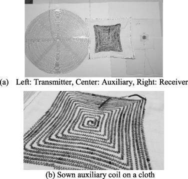
Coils made for wireless power transmission.
The fabricated coils were shown in Fig. 3(a) and (b). Figure 3(b) is an enlarged view of the auxiliary sown coil shown in the middle of Fig. 3(a). The design parameters were shown in Table 3. All coils were made by using litz wires.
Scaling factors of some parameters for coils
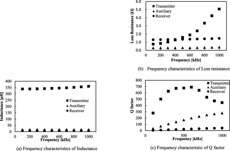
Frequency characteristics of coils.
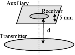
Coils position in measurement of coupling coefficient in 1/2 scaled model.
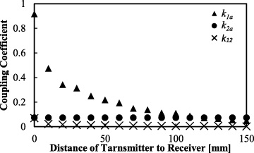
Distance dependence coupling coefficient.

Equivalent circuit used for measuring the power efficient.
Frequency characteristics for the coils were shown in Fig. 4(a), (b), and (c). The Q factor of a coil is given as (1). The inductances of the coils were slightly increased as the frequency. The loss resistance of the transmitter coil was increased significantly as the frequency due to the proximity effect. The Q factor of the auxiliary and the receiver coils was increased as the frequency in the measurement range, while that of the transmitter coil was maximal at the frequency of around 600 kHz.
In this section, the dependence of the coupling coefficients on the distance between the transmitter and the receiver coils is described. The distance between the auxiliary and the receiver coils is fixed to 5 mm. A schematic view of the coils and the positions in the measurement was shown Fig. 5. The 3 coils were set on the central axis. The distance between the receiver coil and the auxiliary coil was kept to be 5 mm. The distance between the transmitter coil and the auxiliary coil was changed from 0 to 150 mm.
Equivalent circuit components value
Equivalent circuit components value
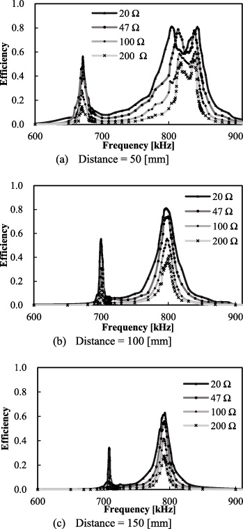
Frequency characteristics of transmission efficiency each distance.
The compare of the maximum transmission efficiency between not using the auxiliary coil and using the auxiliary coil when load resistance was 20 Ω
The measured dependence of the coupling coefficients on the distance was shown Fig. 6. The k12 was the coupling coefficient between the transmitter coil and the receiver coil. The coupling coefficients of the k1a and k2a were the same definition as those described in the Section 2. The k2a was obviously constant to be 0.07 regardless of the distance between the transmitter and the auxiliary coils. The k1a was decreased as the distance and was 0.11 at the target distance of 100 mm. The k12 was very small (< 0.01) over the measurement range.
In this session, the measurement results of the transmission efficiency were described. In the experiment, the distance between transmitter coil and the auxiliary coil is set at 50 mm, 100 mm, and 150 mm. The position of the other coils was the same as that in Fig. 5. The description and the values of the parts in Fig. 7 are summarized in Table 4. The load resistance 20, 47, 100, or 200 Ω was used to investigate the load characteristics of the efficiency. The resonance frequency was set to be around 800 kHz which is corresponded to the frequency of 200 kHz in the full scaled model. An equivalent circuit for the measurement was shown in Fig. 7. Based on Fig. 7, the power transmission efficiency 𝜂 is given as (2). In the equation, V RL is the voltage applied to the load resistance. V1 is a voltage applied to the power transmission side circuit excluding the source resistance R S and R c which is the resistance for measuring the current in the transmission side. θ is the phase difference of V I and the current in the power transmission side. I1 is the current flowing in the transmitter circuit.
Frequency characteristics of the transmission efficiency were shown in Fig. 8(a), (b) and (c). Figure 8(a) shows the efficiency for the distance 50 mm. Two peaks were found between 800 Hz and 860 Hz, which are sometimes found in a two coil system in the case of high kQ products. The efficiency at the distance 100 mm was shown in Fig. 8(b). The distance is a target one in this study. The maximum efficiency 80% at 797 kHz was obtained for the load resistance 20 Ω. The efficiency was decreased as the load resistance because the effective Q factor may be decreased. The efficiency was decreased at a lager distance as shown in Fig. 8(c).
The maximum transmission efficiency between with the auxiliary coil and without the auxiliary coil is shown in Table 5. The transmission efficiency was much more increased than that without the auxiliary coil.
The wireless power transmission system using a sown auxiliary coil for an implantable device was described. The coupling coefficient could be increased by using the sown auxiliary coil. In a transmission experiment, the maximum efficiency without the sown auxiliary coil was 9% when the distance was 100 mm (full scale: 200 mm). The use of the sown auxiliary coil, however, made increase the efficiency to 80%.
The future work is to investigate on operations at a frequency such as 13.5 or 6.725 MHz at which magnetic resonance power delivery, recently, would be used. Also, coupling coefficients and power efficiencies should be investigated in the case that the coils are set off the center axis, because the positions of the coil is changed when the patient with the coils was moved in the bed.