
Abstract
Many communication servers are being installed in order to develop information technology (IT). The servers require not only high-performance processer but also its cooling system. Among the cooling systems, a cooling fan is the most suitable due to good balance between performance and cost. In order to further improve the fan’s performance, both torque and speed of cooling fan motors are increased. However, iron loss and eddy current loss are also increased along with larger torque and higher speed, which worsens the efficiency. This paper investigates the optimum rotor structure for the fan motor in order to obtain sinusoidal flux distribution in air gap, which can reduce the iron and eddy current losses.
Introduction
Many communication servers have been installed to develop information technology (IT). Nowadays, for further development, performance improvement and downsizing of the server are strongly required. According to this, huge local heat of central processing unit (CPU) inside the server becomes serious problem. There are many cooling systems, among them, cooling fans are generally used for removing the heat from CPUs in the communication servers since they have the good balance between cooling performance and cost. In order to further improve the performance, both torque and speed of cooling fan motors are increased. However, iron and eddy current losses are also increased along with larger torque and higher speed, which worsens the efficiency. High efficiency is one of the most important characteristics since the cooling fans never stop rotation, however conventional cooling fan motors has low efficiency because the cost is the most important now, and thereby research papers are also a few [1–3].
To improve the efficiency of the cooling fan motors, reducing the loss or increasing the torque is necessary. This paper focuses on the loss reduction because iron and eddy current losses are increased when both torque and speed of the cooling fan motors are increased to improve the cooling performance.
This paper investigates the optimum rotor structure for the cooling fan motor by a finite element method (FEM) using the JMAG-Designer software ver. 17.1., in order to obtain sinusoidal flux distribution in air gap, which can reduce the iron and eddy current losses. Interior permanent magnet (IPM) rotor is one of the best candidates since eddy current loss in the magnets can be reduced remarkably. However, the general configuration of the cooling fan motor is an outer-rotor type, hence a degree of freedom in design is lower in comparison with a conventional inner-rotor type. First of all, feasibility of Halbach array for the IPM rotor is studied. The optimum magnetization angle of the Halbach array is investigated by FEM. Next, shape of the rotor core is optimized to obtain the sinusoidal flux distribution in the air gap. Finally, characteristics of both motors are compared for the discussion.
Optimizing magnetization angle of Halbach array
Target values of the cooling fan motor
Table 1 indicates the comparison of specifications of a previous fan motor and a target fan motor. As shown in the table, the dimension is equal or less. The rated torque and rotor speed are increased to improve the cooling performance, thereby the mechanical output is about 5 times larger than the previous motor. The target efficiency is 93% at the rated torque.
Comparison of specifications
Comparison of specifications
Halbach array is well-known to obtain the sinusoidal flux distribution in the air gap of permanent magnet (PM) motors, and thereby it can reduce the iron and eddy current losses due to flux harmonic reduction, and also improve the torque owing to increasing the fundamental component of the flux.
Figure 1(a) illustrates flux lines of “parallel magnetization” calculated from 2D-FEM. The magnets are placed in the air space. It can be seen from the figure that the flux lines are uniformly distributed. On the other hand, Fig. 1(b) shows flux lines of “Halbach array”. As shown in the figure, the flux is enhanced on one side and the other side is weakened.
Figure 2 shows the comparison of calculated flux density distribution on the surface of the magnets. The flux density at the center position of Halbach array is about 1.5 times larger than that of “parallel magnetization”. Therefore, the torque is expected to be increased by Halbach array. However, Halbach array is generally applied to surface permanent magnet (SPM) motor [4–6]. In the next section, feasibility of Halbach array for the IPM rotor is studied. The optimum magnetization angle of the Halbach array is investigated by 3D-FEM.
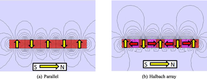
Flux line of magnets in the air.
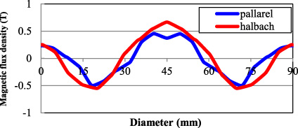
Comparison of calculated flux density distribution on the surface of the magnets.

Schematic diagram of the first proposed motor and magnetization angle of Halbach array magnets.
Figure 3 shows schematic diagram of the first proposed motor and the magnetization angle of Halbach array magnets. The motor has a 6-slot stator with three-phase concentrated windings and a 4-pole IPM rotor. As shown in the figure, each pole consists of 4 pieces of magnets. The magnet material is sintered Nd–Fe–B. The core material is non-oriented silicon steel with a thickness of 0.35 mm. Table 2 shows specifications of the fist proposed motor.
The Halbach array is generally applied to SPM motor and not to IPM one. To investigate the feasibility of Halbach array for the IPM motor, the optimum magnetization angle of a pair of outside magnets (θ1) and a pair of inside magnets (θ2) are found by Brute-force search.
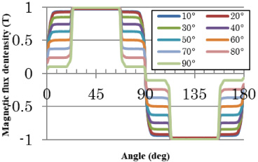
Figure 4 shows one example of calculated flux density distribution in the air gap when a magnetization angle of a pair of inside magnets (θ2) is fixed at 15 deg. and that of outside magnets (θ1) are changed from 10 to 90 deg. It is understood from the figure that the magnetic flux distribution cannot be sinusoidal by Halbach array method.
Figure 5 indicates flux lines calculated by 2D-FEM when the magnetization angle of a pair of inside magnets (θ2) is 15 deg. and that of outside magnets is 80 deg., respectively. It is clear that the fluxes from the outside magnets does not flow to the center of the pole but to the opposite direction by the thin iron on the rotor surface. Hence, Halbach array is not suitable for IPM motor.
Specifications of the first proposed motor
Specifications of the first proposed motor
Calculated magnetic flux density.
Flux lines of first proposed motor.
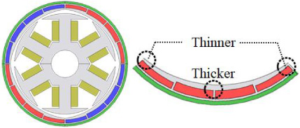
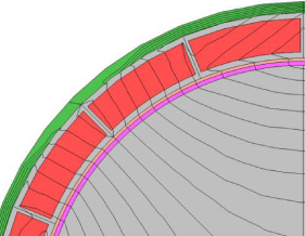
Schematic diagram of the second proposed motor.
Specifications of the second proposed motor
Concept of shape design of the rotor core and results
In the previous section, it was clear that the thin iron covering the magnets drastically changes the direction of flux lines, that is, not the magnets but the rotor core is the key to obtain the sinusoidal flux distribution for the IPM motor. Based on the above idea, the rotor core was designed so that the sinusoidal flux distribution can be obtained. Figure 6 shows schematic diagram of the second proposed motor. As shown in the figure, the rotor core at the center of magnetic pole is thicker, while the edge is thinner, in order to concentrate the fluxes of the magnets to the center of magnetic pole. Corresponding to changing the rotor core shape, the thickness of the magnets should be changed. Therefore, the amount of magnet of the second proposed motor is less than that of the first proposed one. The magnets are simply magnetized in the radial direction. The stator has the same shape and specifications as the first proposed motor. Table 3 indicates specifications of the second proposed motor.
Figure 7 shows calculated flux density distribution in the air gap. The figure reveals that the sinusoidal flux distribution can be obtained by changing the thickness of the rotor core according to the angle. Figure 8 shows the comparison of harmonic spectrums of flux density distribution shown in Fig. 7. The figure reveals that the harmonic components are remarkably reduced in the second proposed motor. Figure 9 indicates flux lines of the second proposed motor. It is understood from the figure that the flux lines of the second proposed motor are concentrated to the center of magnet pole because it has the structure that magnetic reluctance is low at the center of magnetic pole, while it is high at the edge. Based on the result, characteristics of the second proposed motor are calculated and compared to the first proposed motor.
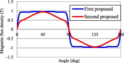
Magnetic flux density of the first and second proposed motor.

Comparison of harmonic spectrum of the first and second proposed motor.
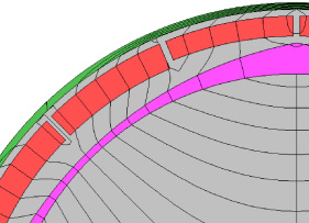
Flux line of second proposed motor.
Figure 10(a) shows the comparison of torque characteristics. Both torques are almost the same because the magnetic flux densities are almost the same too. But, the amount of magnet used in the second proposed motor is less than that of the first one. Figure 10(b) indicates the copper loss. Both copper losses are also the same due to the same torque characteristic. On the other hand, as shown in Fig. 10(c), the iron loss of the second proposed motor is about 1 W less than that of the first one since the harmonic contents of the flux are small in comparison with the first proposed motor as shown in Figs 4 and 7. Figure 10(d) shows the comparison of eddy current loss in the magnets. The eddy current loss of the second proposed motor is also smaller than that of the first one due to sinusoidal flux distribution. Figure 10(e) indicates the efficiency comparison. It is found that the second proposed motor has higher efficiency, especially at light load region since the iron and eddy current losses are decreased. The efficiency at the rated toque reaches 93% of the target value.

Comparison of characteristics of the first and second proposed motors.
This paper investigated the optimum rotor structure for the cooling fan motor by using FEM, in order to obtain sinusoidal flux distribution in the air gap, which can reduce the iron and eddy current losses.
First, feasibility of Halbach array for the IPM rotor was studied. Although the optimum magnetization angle of the Halbach array was investigated, the sinusoidal flux distribution cannot be obtained since the fluxes from the outside magnets does not flow to the center of the pole but to the opposite direction by the thin iron on the rotor surface. It was clear that Halbach array is not suitable for IPM motor.
Next, shape of the rotor core was optimized to obtain the sinusoidal flux distribution. As a result, when the rotor core at the center of magnetic pole is thicker, while the edge is thinner, the sinusoidal flux distribution can be obtained since the fluxes from the magnets are concentrated to the thick region of the rotor core.
The iron and eddy current losses of the second proposed motor are less than those of the first one due to the sinusoidal flux distribution. As a result, the efficiency is also higher, especially at light load region.