
Abstract
This paper proposes a permanent magnet assisted brushless wound rotor synchronous machine (PMa–BL–WRSM) design. The proposed machine has the advantage of a high starting torque compared to existing BL–WRSM topologies. Additionally, the average torque increases and the torque ripple is reduced when the permanent magnet assisted machine structure is used. PMa–BL–WRSM operates on the principle of brushless excitation using zero-sequence, third-harmonic current generation in the stator windings. The third harmonic component is harnessed to induce a voltage in the harmonic winding which is mounted on the rotor. As there is no flux generated from filed winding in the starting, the starting torque of the machine is also zero. To overcome the problem, permanent magnets (PMs) are inserted in each field tooth to provide the initial source of flux on the rotor. Finite element analysis is performed with the PM–BL–WRSM, and the elicited results are compared with the basic machine structure. The proposed machine operation is verified using 2-D finite element analyses using the ANSYS Maxwell analysis tool.
Introduction
Wound rotor synchronous machines (WRSMs) are magnet-free synchronous machines that utilize rotor windings to generate flux. The effectiveness responses of WRSMs were analyzed in [1]. Synchronous motor drive was also investigated as a viable option for many applications for their better performance compared with permanent magnet synchronous machines [2]. In [3], a WRSM was designed and analyzed for a belt-driven e-Assist system, and its performance was compared with that of an interior permanent magnet synchronous motor (IPMSM). It was shown that a WRSM is 5% more efficient at high speeds than an IPMSM.
However, the WRSM requires brushes and slip rings, which experience losses and sparking, and require maintenance. Alternatively, permanent magnet (PM) reduction in PM machines have been extensively studied to decrease the manufacturing cost of the machines. In this regard, excitations of hybrid machines with both PMs and electrical excitations have been discussed in [4]. A hybrid, doubly excited synchronous machine, has been introduced for direct drive applications in [5]. However, in such machines, the design becomes complicated and introduces control and manufacturing complexity. Eventually, brushless wound rotor synchronous machine (BL–WRSM) topologies have been researched to avoid all the aforementioned problems [6–10]. The brushless operation is advantageous in terms of cost-effectiveness and control flexibility compared to permanent magnet synchronous machines (PMSMs) or hybrid excited machines.
In [6], brushless excitation scheme was studies for wound rotor synchronous machine for power generation. In another research study, brushless wound field synchronous machine was investigated to be optimized for utilizing in hybrid electric vehicles [7]. For the same purpose of using the machine in electric vehicle, a capacitive field excitation scheme was used in [8]. Third harmonic injection based schemes were introduced in recent years for the brushless operation of the machine by utilizing air-gap harmonics deliberately created for excitation [9,10]. The major drawback of the BL–WRSMs is their low starting torque. In [11], a PM assisted BL–WRSM was presented to overcome the problem of low-starting torques. However, the use of a dual inverter resulted in the increased cost and size of the system.
In this study, a PM assisted BL–WRSM (PMa–BL–WRSM) is proposed to improve the starting and average torque characteristics based on a recently introduced BL–WRSM topology [12]. Figure 1 shows the schematic diagram of the BL–WRSM for generating a third harmonic component to excite the rotor winding from a single inverter.
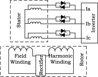
Schematic diagram of BL–WRSM.
The brushless operation of the proposed machine is based on the topology shown in Fig. 1 [12]. Figure 2(a) and (b) respectively show the basic and PM-assisted machine model for brushless WRSM. The proposed PMa–BL–WRSM design contains PMs inserted in the rotor field teeth to strengthen the rotor field flux.
At startup, the induction current in the harmonic winding is zero and the current fed to the field winding is also zero. Consequently, the torque of the machine is zero. The PMs of the rotor produce a constant flux, and the interaction with the armature’s magneto-motive force (MMF) generates a startup torque. As the current is induced in the rotor windings, the interaction of the armature MMF with the rotor field winding flux also produces torque.
To conduct the finite element analyses, a 48-slot, eight-pole machine is designed, as shown in Fig. 2. The operating parameters are listed in Table 2. To adjust the harmonic winding, each tooth of the field winding has been designed using an extra slot. The location of the PMs is exactly above the harmonic winding conductors in each slot, as shown in the machine layout in Fig. 2(b).
At steady state, the machine operates based on the generated fluxes from both the PMs and field windings. Therefore, the average torque is increased. As the PMs on the rotor field teeth do not affect the fundamental and third harmonic MMF, only the increased PM flux increases the average torque. To achieve a maximum flux increment and alignment with the field flux, the PM in each tooth is placed exactly at the center of the field tooth shoe.
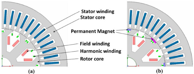
(a) Basic model. (b) PMa–BL–WRSM.
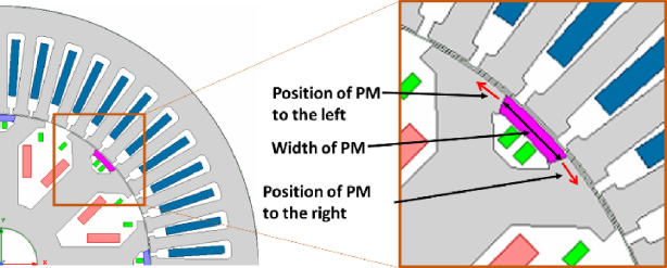
Positioning and width of the PM.
Parameters of the machine model for simulation
The operation of the wound rotor synchronous machine is conducted according to the principle of synchronizing the field flux, which results from the dc current fed through the slip rings and brushes. To make this machine brushless, the field current must be provided from within the machine structure. In this study, an inverter supplies power to the stator winding as shown in the topology in Fig. 1. Antiparallel thyristors are connected in parallel to each of the three phases of the stator’s winding. The switching action occurs repeatedly near the zero crossings and results in zero-sequence third harmonic currents, which flow in the same three-phase armature windings. This arrangement on the stator generates two types of currents in the stator windings. Eventually, two components of air-gap MMF are generated: the fundamental and third-harmonic MMF.
To extract the harmonic power from the stator, additional windings are mounted on the rotor known as harmonic windings. The field winding is mounted on the rotor to produce field flux to be synchronized with the fundamental MMF. An uncontrolled diode rectifier is also mounted on the rotor between the two windings, as shown in Fig. 1. The third-harmonic current generated in the stator winding induces a voltage on the 24-pole harmonic winding of the rotor. The current in the harmonic winding is rectified by the diode rectifier and fed to the eight-pole field winding. Therefore, the field winding is excited so that it can be synchronized with the stator winding.
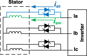
Diagram showing the paths of switching current flow in blue color and the winding current flow in green color.
Regarding phase-A, the paths of switching and winding currents are respectively shown in Fig. 4 with arrowheads identified in blue and green colors. The brushless operation is based on the division of the inverter current in two paths, as illustrated in Fig. 4. In this way, the rotating MMF is produced from the current that flows in the winding when the thyristor switches are turned off. During the switching time, the current path is changed from the winding to the switch branch. The inverter fed current are sinusoidal varying with each phase at 120° phase shift. Three-phase currents from the inverter are calculated as
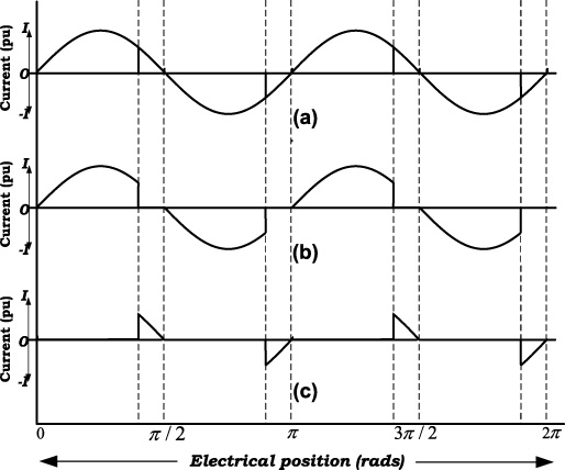
Diagram showing the waveforms of the (a) phase, (b) winding, and (c) switching currents.
When the thyristor pulse is positive and equal to unity, the instantaneous current flows in the switch branch, and it is zero otherwise. Interpretation of Eq. (2) is illustrated in Fig. 5 for the case of phase-A currents. The switch branch current is illustrated with a solid-line curve and the winding branch current is illustrated with a dashed-line curve.
The proposed design of the machine is analyzed using the finite element analysis tool ANSYS Maxwell 19.0. By no-load voltage comparison the PMa-BL-WRSM design exhibits higher back EMF (electro-motive force) compared to BL-WRSM design. The waveforms of both the models are shown in Fig. 6(a) whereas the harmonic contents are compared in Fig. 6(b). It is observed that the back EMF of PMa-BL-WRSM is more sinusoidal in shape which is depicted in the harmonics contents where the fundamental component (60 Hz) frequency has higher magnitude voltage in PMa-BL-WRSM. Eventually, the higher harmonics have lesser voltage magnitude in PMa-BL-WRSM compared to BL-WRSM.
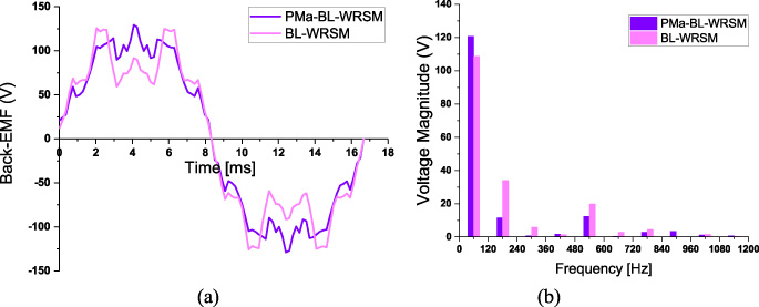
Back EMF comparison of BL-WRSM, PMa-BL-WRSM. (a) Waveform of Phase-A. (b) Harmonic content of Phase-A.
The PM width is maintained at 6 mm initially and it is increased up to 11 mm in different simulations. However, by increasing the width by more than 11 mm, the flux density on the field tooth increases, which causes torque ripples owing to saturation. Additionally, the position of the PM was also moved to the left and right edges of the tooth shoe to decrease the flux saturation. Figure 7 (a) shows the graph of the starting torque obtained using simulations based on variations in the magnet width and position. A similar trend is achieved in the case of the average torque of the machine, as shown in Fig. 7(b).
Increasing the PM width increases the starting and average torque values. However, the PM flux must be aligned with the field flux to obtain a maximum starting torque. The position was changed by 1.8 mm to the left and 1.8 mm to the right. Based on the position and width, the results are compared in Fig. 8(a) for the starting torque and in Fig. 8(b) for the average torque. Based on the simulations, it is shown that the starting and average torque values for a PM width of 1.8 mm on the right side of the center field tooth are higher compared to the PMs at the center and at positions on the left owing to the fact that the flux saturation is low on the right side of the tooth.

Trends of the (a) starting torque and (b) average torque as a function of the PM width.
Figure 8(a) shows that the starting torque increases as the position of the magnet is changed from left to center and then to right. At the same time the starting torque is dependent on the width of the magnet.
Therefore, a small amount of magnet can be used and position can be adjusted to right side to decrease flux saturation on the left side.
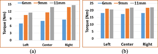
(a) Comparison of the (a) starting and (b) average torque values as a function of the PM width at the set width values of 6, 9, and 11 mm, and at left, center, and right locations.
The starting and average torque values in the case of highest magnitude are compared to the respective responses elicited in Fig. 9(a) and (b), respectively. The results are also summarized in Table 2.
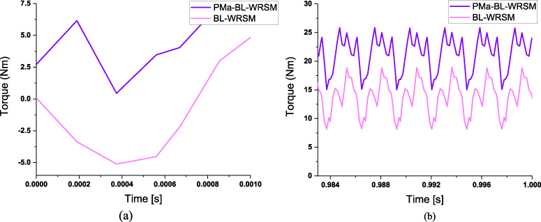
(a) Starting torque of basic BL–WRSM and PMa–BL–WRSM, (b) average torque of basic BL–WRSM and PMa–BL–WRSM.
Torque comparison of basic and PMA–BL–WRSM model
This study proposed the use of the PMa–BL–WRSM to increase the starting torque for brushless operation of the machine when it was connected to a load. The PM inserted in the field teeth was optimized for its width and position. Improved results were obtained regarding its starting and average torque values without increase in the torque ripples. Finite element analyses were performed using the ANSYS Maxwell tool.