
Abstract
The EMAT (electromagnetic acoustic transducer) has been used to measure the thickness of the metallic plate in some industries recently. Comparing with the piezoelectric transducer, its low energy conversion efficiency due to the lift-off effect limits its further application. Based on the eddy current energy partition, the distances between the copper sheet and the coils are studied. In consideration of the influence of magnetic flux density, a principle about the energy conversion efficiency and the coils position is proposed. The optimal distances between the copper sheet and the coils under a certain lift-off are obtained through a series of simulation and experiment. The results offer a method for the EMAT structure design.
Introduction
EMATs do not need coupling agent which is a significant advantage over piezoelectric acoustic transducer, so it is usually used in the noncontract non-destructive testing [1]. Conventional EMATs include an induction coil and permanent or direct current magnet. The coil induces eddy currents into a metal specimen. The induced eddy currents and the magnetic field generated by the magnet results in oscillating Lorentz force, i.e., ultrasound excitation in the specimen. EMAT receiving process is the reverse process of excitation process. The EMAT energy transfer process involves the coupling between electric field, magnetic field and mechanical field. The complex coupling process leads to low conversion efficiency, which limits the application of EMATs [2].
The lift-off between the specimen and the EMAT has a significant effect on energy conversion efficiency, there are plenty of previous studies focused on solving the problem of low energy efficiency with large lift-off [3,4]. In some EMATs, in order to prevent the eddy current and vibration generated in the permanent magnet, soft magnetic materials, such as silicon steel laminations, are used as back-plates to increase the efficiency of EMATs by increasing the magnitude of the EMAT coil’s dynamic magnetic field and the eddy current in the specimen surface [5]. In other transducers, a backplate made of copper sheet is used to shield the permanent magnet from dynamic electromagnetic field. However, the copper sheet will dissipate energy in the form of eddy currents. Therefore, the effect of the exciting coil position on energy conversion efficiency has been studied, an equivalent circuit model is proposed to analysis the optimal distance among copper sheet, exciting coil and specimen [6]. Most studies focus on the non-ferromagnetic specimen and neglect the influence of receiving coil. Compared with non-ferromagnetic material, the mechanism of ferromagnetic material testing using EMAT is more complex. In the ferromagnetic material testing, the generation mechanism of acoustic waves includes Lorentz force, magnetostrictive force and magnetizing force, eddy current dissipation rate is smaller and the characteristics of dynamic electromagnetic field are different.

Energy partition system diagram.
In this paper, to investigate the effect of exciting coil and receiving coil position on EMAT conversion efficiency simulations and experiments are carried out to study the EMAT with the copper sheet when the tested specimen is ferromagnetic material.
As mentioned above, to generate ultrasonic waves, the EMAT induces eddy currents in the specimen. In the meantime, eddy currents are also induced in the other parts of the EMAT and the energy will be dissipated, which is not useful for generating the ultrasound. The EMAT energy conversion efficiency is closely related to the eddy current energy partition ratio between the specimen and other parts of the EMAT.
Energy partition principle
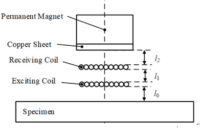
First of all, a simple electromagnetic system model was built to study the basic principle of eddy current energy partition as shown in Fig. 1. When an alternating current passes through the exciting element, the original electromagnetic field generated by the current transmits the excitation energy to the receiving elements. The ratio of energy partition between the two elements is determined by the electromagnetic characteristics and the locations of the elements. Thus, when the electromagnetic characteristics of the elements are determined, the ratio of energy partition can be changed by changing the position of the elements. For example, when the receiving element 1 moves close to the exciting element, the mutual inductance between them increases and generates a larger induction current in receiving element 1. The magnetic flux density generated by exciting element and receiving element 1 in receiving element 2 is denoted as B0 and B1, respectively. According to Faraday law of electromagnetic induction, the induced voltage in receiving element 2 can be calculated by the Eq. (1):
EMAT schematic diagram.
In other words, when the receiving element 1 moves close to the excitation element, according to Lenz’s law, the magnetic flux density generated in the receiving element 1 will increase, the magnetic flux density B and the induced current on the receiving element 2 will decrease. The energy partition ratio between the receiving element 1 and the receiving element 2 will change with the induced energy increasing in the receiving element 1 and decreasing in the receiving element 2. The energy partition principle can be applied to EMAT structure design and improve the conversion efficiency.
The EMAT as shown in Fig. 2 can be regarded as an electromagnetic system, so it is also ruled by the energy partition principle. The EMAT includes a permanent magnet which provides static magnetic field, a copper sheet, an exciting coil and a receiving coil. In the exciting process, the exciting coil which conducts the exciting current is an exciting element, other parts of the system are the receiving elements which receive energy from the exciting current. Therefore, from the perspective of energy partition, the energy partition ratio between the specimen and other parts of the EMAT can be obtained. Further, the influence of coils position on energy conversion efficiency in the EMAT can be studied
According to the principle of energy partition, when the lift-off between the exciting coil and the specimen is fixed, the eddy current induced by the exciting coil in the specimen will increase if the receiving coil and the copper sheet move away from the exciting coil. Owing to the copper sheet is attached to the permanent magnet, increasing the distance between the copper sheet and the specimen will reduce the magnetic flux density in the specimen which is provided by the permanent magnet. However, the vibration amplitude of the specimen depends on the Lorentz force
From the above analysis, when the distance between the copper sheet and the exciting coil increases, the eddy current
Simulation model.
Based on the principle of energy partition and considering the influence of magnetic flux density, an assumption about the relationship between the coils and energy conversion efficiency is proposed: By adjusting the coils position in the EMAT, the relationship between eddy currents and magnetic flux density in the specimen can be balanced, and a better energy conversion efficiency can be obtained.
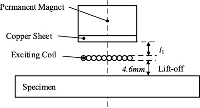
To verify the correctness of the assumption and obtain the influence of distance on magnetic flux density and Lorentz force, simulations were conducted as shown in Fig. 3. During the excitation process, the receiving coil is equivalent to the copper sheet, so the receiving coil is ignored to simplify the simulation model.
Simulation settings
With the lift-off of the specimen and the exciting coil increase, the energy conversion efficiency of EMAT decrease sharply. Therefore, the emphasis of simulation optimization is the energy conversion efficiency of EMAT system under the condition of large lift-off. As shown in Fig. 3, the lift-off can be fixed at 4.6 mm, and the only variable is the distance between the copper sheet and the exciting coil.
The permanent magnet made of N52 magnet is a cube with 40 mm side length, and the coercivity is 955 kA/m. The copper sheet is a square with 40 mm side length and 0.5 mm thickness. The thickness of 23 turns exciting coil is 0.5 mm and the out diameter is 25 mm. The current amplitude in the excitation coil is 5 A and the frequency is 1 MHz. The specimen in simulation is Q235 steel and is 8 mm thick. The finite element software ANSYS was used to calculate the eddy current and magnetic flux density distribution in the specimen, and the value of a reference point is selected to represent the eddy current and magnetic flux density to evaluate the conversion efficiency. Since the exciting current is a high-frequency alternating current, the depth of the reference point must be located within the skin depth. The conductivity (1.2e6 S/m) and permeability (1.8e-4 H/m) of the specimen are substitute in the Eq. (3), and the skin depth of the specimen can be calculated as 0.11 mm. Therefore, the test point of the simulation was selected to be 0.05 mm away from the surface of the specimen and 5 mm away from the magnet axis.
As can been seen from the Figs 4–6, the simulation results are basically consistent with the assumption. The general rule is that the eddy current in the specimen rises with the increase of l1 and the magnetic field decreases with the increase of l1. Under the 4.6 mm lift-off between the exciting coil and the specimen surface, both changing rates of magnetic flux density and eddy current are comparable. Therefore, the Lorentz force density in the specimen is affected by both eddy current and magnetic flux density, showing a tendency of first increasing then decreasing with the increase of l1. Obviously, there is an optimal distance in the EMAT that can balance the contradiction between the eddy current and the magnetic field. To find the optimal distance and improve the energy conversion efficiency, further experiments are carried out in the following.
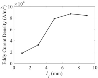
Relationship between the eddy current density and l1 in simulation.
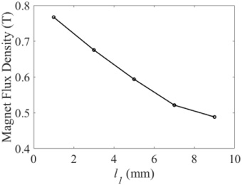
Relationship between the magnetic flux density and l1 in simulation.

Relationship between the Lorentz force density and l1 in the simulation.
The simulation preliminarily verified the assumption of eddy current and Lorenz force, but the influence of receiving coil is ignored. Considering the influence of receiving coil, an experiment with multiple coils positions was designed to further verify the assumption and to optimize the EMAT structure.
Experiments
The schematic diagram of the EMAT is shown in Fig. 2 above, and the schematic diagram of the EMAT thickness measurement system in the experiment is shown in Fig. 7. The cube permanent magnet with 40 mm side length is placed in the stainless steel shell. The bottom surface of the shell is slotted for placing square racetrack coils and copper sheet.
Step one experiment settings
Step one experiment settings
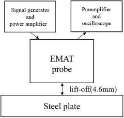
Schematic diagram of the EMAT experiment setup.
As in the simulation, the aim of the experiment is also to improve the EMAT performance under the large lift-off. The epoxy plates are used to lift the transducer to simulate the lift-off in the experiment, and the distance between the exciting coil and 8 mm Q235 steel plate is 4.6 mm.
In the simulation, the only variable is the distance between the copper sheet and the exciting coil. Since the influence of the receiving coil is considered in the experiment, the variables of the experiment are the distance between receiving coil (l1 in Fig. 2) and the distance between receiving coil and the copper sheet (l2 in Fig. 2). Thus, the experiment was divided into two steps to explore the influence of the coil position on the energy conversion efficiency. The first step as shown in Table 1 is to change l1 while keeping l2 unchanged to find the law that the received signal amplitude changes with l1. According to the simulation results, the optimal l1 can be obtained when the received signal amplitude reaches the maximum value. The second step is to fix l1 at the optimal value and change the value of l2, and the optimal value of l2 also can be obtained using the same method.
The evaluation of the energy conversion efficiency in this paper is based on the signal amplitude. The signal amplitude is amplified by the signal conditioning circuit by 100 db. However, the signal amplitude is seriously disturbed by noises. Therefore, the receiving signal is obtained after 64 times average acquisition by Teledyne 3024 200 MHz oscilloscope. The receiving signals of the first step are shown in Fig. 8(a–e). Since the excitation current of EMAT will generate induced voltage directly on the receiving coil during excitation, and hence the induced voltage will block the amplifier, this initial period is about t < 5e-5 s and generally called ‘paralyzed time’. After the paralyzed time, the receiving coil begins to receive the signal normally. So, the signal at about t > 5e-5 s is the useful echo signal.

The receiving signals at different l1 and their relationship. (a) l1 = 0.5 mm. (b) l1 = 1 mm. (c) l1 = 1.5 mm. (d) l1 = 2 mm. (e) l1 = 2.5 mm. (f) Relationship between the received voltage level and l1 in the experiment.
The amplitude of a single echo signal is unstable. Therefore, the feature amplitude, which is the average of the absolute value of the signal amplitude within 5e-5 s to 15 e-5 s, is employed to evaluate the energy. And it is obviously showing a trend of first increase and the decrease with the increase of l1. The maximum amplitude of received signal appears when l1 = 1.5 mm, which is taken as the optimized value of l1. The second experiment was conducted based on this value. The results of the experiment are shown in Fig. 9(a–d).
The experiment shows that l1 = 1.5 mm, l2 = 1 mm is the optimal structure parameter of the EMAT to maximize the signal amplitude. In the experiment, the maximum value of the received signal amplitude increase by 40% compared with the minimum value. Therefore, it can be concluded that the distance between coils and copper sheet will significantly affect the energy conversion efficiency of EMAT under the condition of large lift-off.

The receiving signals and the relationships at different l2. (a) l2 = 0 mm. (b) l2 = 0.5 mm. (c) l2 = 1.5 mm. (d) Relationship between the received voltage level and l2 in the experiment.
The principle based on the eddy current energy partition is proposed to optimize the positions of the coils in the EMAT and the energy conversion efficiency. The simulations and experiments were conducted to prove the correct of the principle. The simulation result show that the exciting energy will be partitioned among the copper sheet, coil and specimen and the eddy current energy in the specimen depends on the position of the coil. In the experiment, considering the influence of distance on the static magnetic flux density, there is an optimal coil position in the EMAT under a certain constant lift-off, which can balance the contradiction of magnetic flux density and eddy current, and improve the energy conversion efficiency. All these works illustrate how the coil position affects the energy conversion efficiency in the EMAT and provides guidance for the EMAT structure design.
Footnotes
Acknowledgements
This work was supported by the CNPC research and development project “Development and application of key technologies for risk control of hazardous chemicals (2017D-4612)” and “The National Key Research and Development Program of China (Grant No. 2017YFF0209701)”.