
Abstract
Clamping devices with constant force or pressure are desired in medical device, such as hemostatic forceps and the artificial sphincter, to prevent soft tissues from injures due to overloading. It is easily obtained by stretching an SMA wire. However, studies with SMA bending round bar have seldom been reported before. This paper studied constant force characteristic of C-shaped round bar with shape memory alloys. Optimization designs of the components were carried out with computational simulation. Numerical results show that the phenomenon of constant force strongly depends on contour curve shape and geometric dimensions of the C-shaped round bar of SMA component.
Introduction
In medical instruments such as hemostatic forceps and the artificial sphincter, clamping devices for soft tissues of the human body are commonly used. It is considered that hemostatic forceps should satisfy at least three criteria, namely hemostasis, slip resistance, and atraumatic function [1]. However, to prevent slippage and achieve hemostasis, excessive pressure is often applied. Hemostatic forceps have a long history of over half a century, but remain having the potential of excessive pressure induced lesion [2,3]. A serious lesion due to the excessive pressure from forceps may sometimes leads to the death of patients in cardiovascular surgery, brain surgery and other surgeries. The artificial sphincter also has same problem [4,5].
Clamping the soft tissue of human body with constant force or pressure in a safe range is considered as an effective solution for this issue, the reason is that excessive pressure can cause soft tissue injury and low pressure can cause soft tissue slippage. Constant force can be generated by hydraulic, pneumatic, or electric drives, but these systems usually need a complex control algorithm [6]. Other researches employ compliant mechanism or rigid components and linear springs to obtain constant force [7–10]. However, these mechanisms are complicated and need larger space.
Constant force can be realized using the superelastic mechanical properties of shape memory alloys (SMA) during its stress-induced transformation. It is easily obtained by stretching an SMA wire. However, studies with SMA bending round bar have seldom been reported before. The component using C-shaped SMA bending round bar has the advantage of smaller space occupation. It is studied constant force property of C-shaped round bar with shape memory alloys. Numerical optimization has been done by varying contour curve shape and geometric dimensions of the SMA bending round bar to obtain approximately constant force in a relatively large deformation range.
Materials and method
Materials and boundary conditions of the simulation
A C-shaped round bar of SMA was selected as the base model of constant force component. The sleeves connected to the pins were designed to simulate for applying load on ends of round bar. The structure of the model is shown in Fig. 1a. The mechanical property of the structure was simulated using finite element method.
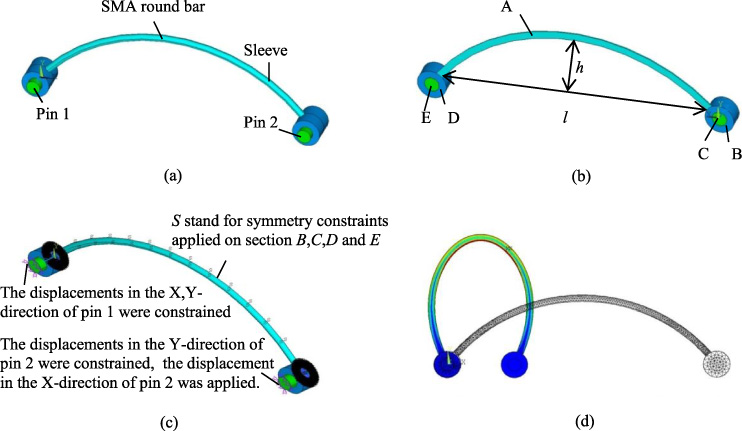
The C-shaped SMA model with round bar. (a) C shape SMA round bar. (b) The dimension parameters and the constrained surfaces of model. (c) The boundary conditions of model. (d) The deformation of model.
The material and geometric parameters and boundary conditions of the simulation were as follows:
(1) The material of the round bar was defined as SMA. A unique characteristic of superelastic SMA is the constant stress during their stress-induced transformation. The constitutive model on which this numerical method is based the Auricchio model [11]. The stresses of start and finish points of phase transformation from austenite to martensite were 550 MPa and 600 MPa, respectively. The stresses of start and finish points of phase transformation from martensite to austenite were 300 MPa and 200 MPa, respectively. The modulus of elasticity is 40,000 Mpa and the Poisson’ratio is 0.3. The response difference of material tension-compression was 0.12, and the residual strain was 0.07. The material of the pin and sleeve was defined as rigid body with elastic modulus of 150,000 MPa and Poisson’s ratio of 0.25.
(2) The equation for the contour curve of round bar was
(3) The contact pair was established using element target170 and contact174 between pin and sleeve, and the contact parameter fcn was 0.1.
(4) Symmetry constraint was applied to area A, B, C, D and E, the displacement in X, Y -direction for key points of pins 1 was constrained, the displacement in Y -direction for key points of pins 2 was constrained, and the displacement in X-direction was applied on pins 2, as shown in Fig. 1b–c. The deformation of model is shown in Fig. 1d.
The reaction force in X-direction on key points of pins 2, and the internal stress in the round bar were collected during the numerical simulation.
The chord height h, chord length l and cross-sectional diameter d of the round bar were optimized to obtain lager deformation range within which the force is nearly constant. The relation between the internal stress distribution in round bar and obtained displacement-force behavior was analyzed. The optimization process is as follows:
Case 1: The effect of the chord height of round bar on the force-displacement curve was studied. The cross-sectional diameter d and chord length l of the round bar were both fixed, while the chord height of h round bar was altered. The cross-sectional diameter d was set to be 1 mm and the chord length l was set to be 40 mm, 50 mm respectively. The chord height h is taken between 2 mm and 20 mm.
Case 2: The effect of the chord length of round bar on the force-displacement curve was studied. The cross-sectional diameter d and chord height h of the round bar were both fixed, while the chord length l of round bar was altered. The cross-sectional diameter d was set to be 1 mm and the chord height h was set to be 5 mm, 6 mm respectively. The chord length l is taken between 20 mm and 100 mm.
Case 3: The effect of the cross-sectional diameter of round bar on the force-displacement curve was studied. The chord height of h and chord length l of the round bar were both fixed, while cross-sectional diameter d round bar was altered. The chord length l was set to be 40 mm and the chord height h was set to be 6 mm, 14 mm respectively. The cross-sectional diameter d is taken between 0.5 mm and 2 mm.
Results and discussion
Figure 2 shows the force-displacement curves of SMA round bar for Case 1. To gain a better constant force property, the optimization objective is to make the value of the slope for the fitting line of the curve close to zero as much as possible. As those force-displacement curves are relatively dense, only one of the fitting lines of the curves has been drawn, which suggests the best result. Figures 2a–b shows the force-displacement curves of round bar with the chord length l of 40 mm and 50 mm respectively. In Fig. 2a, curves C1–C5 are force-displacement curves with chord height h set to be 6 mm, 8 mm, 10 mm,12 mm and 14 mm respectively. The slopes of the fitting lines for C1–C5 are showed in Table 1 and the slope of curve C3 is closest to zero. Namely, the best constant force property can be obtained using SMA round bar with cross-sectional diameter d of 1 mm, the chord length l of 40 mm and chord height h of 10 mm, as shown in Table 1. In Fig. 2b, curves C1–C5 are force-displacement curves with chord height h set to be 5 mm, 7 mm, 9 mm, 11 mm and 13 mm respectively. The slopes of the fitting lines for C1–C5 are showed in Table 1 and curve C3 is optimal as the slope of its fitting line is closest to zero.
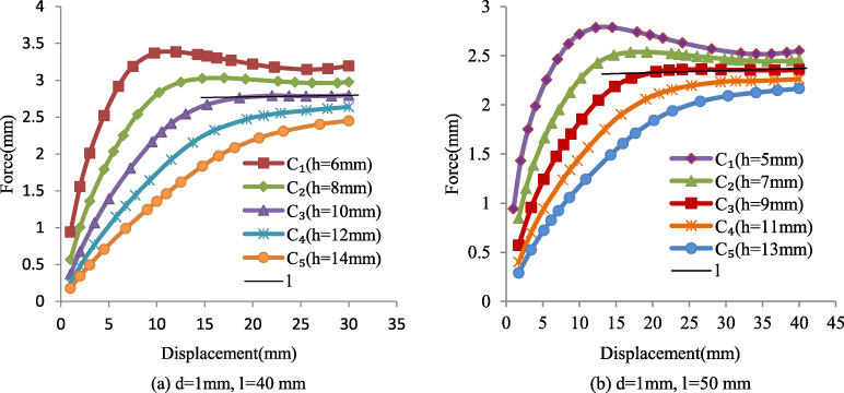
Force-displacement curves for the round bar with different chord heights.
The simulation results for the chord height of C-shaped round bar as the variable

Force-displacement curves for the round bar with different chord lengths.
The simulation results for the chord length of C-shaped round bar as the variable
Namely, the best constant force property can be obtained using SMA round bar with cross-sectional diameter d of 1 mm the chord length l of 50 mm and chord height h of 9 mm. The slope of fitting line corresponding to curve C1–C5 increases gradually from negative to positive, and there must be a curve with slope of 0, that is, there exists a curve with optimal constant force characteristics, as shown in Table 1. It is illustrated that varying the chord height of the SMA round bar may obtain a better constant force property.
Figure 3 shows the force-displacement curves of SMA round bar for Case 2. Figures 3a–b shows the force-displacement curves of round bar with the chord height h of 5 mm and 6 mm respectively. In Fig. 3a, curves C1–C4 are force-displacement curves with chord length l set to be 50 mm, 60 mm, 70 mm and 80 mm, respectively. The slopes of the fitting lines for C1–C4 are showed in Table 2, and the slope of curve C4 is closest to zero. Namely, the best constant force property can be obtained using SMA round bar with cross-sectional diameter d of 1 mm, chord height h of 5 mm and the chord length l of 80 mm as shown in Table 2. The simulation results of Case1 show that the constant force characteristics are poor for SMA round bar with cross-sectional diameter d of 1 mm, chord height h of 5 mm and chord length l of 50 mm. It is illustrated that varying the chord length of the SMA round bar may obtain a better constant force property. In Fig. 3b, curves C1–C5 are force-displacement curves with chord length l set to be 40 mm, 50 mm, 60 mm, 70 mm and 75 mm respectively. The slopes of the fitting lines for C1–C5 are showed in Table 2, and curve C5 is optimal as the slope of its fitting line is closest to zero. Namely, the best constant force property can be obtained using SMA round bar with cross-sectional diameter d of 1 mm, chord height h of 6 mm and the chord length l of 75 mm, as shown in Table 2. The simulation results of Case1 show that the constant force characteristics are poor for SMA round bar with cross-sectional diameter d of 1 mm, chord height h of 6 mm and chord length l of 40 mm. The results show that varying the chord length of the SMA round bar may obtain a better constant force property.

Force-displacement curves for the round bar with different various cross-sectional diameters.
The simulation results for the cross-sectional diameter of C-shaped round bar as the variable
Figure 4 shows the force-displacement curves of SMA round bar for Case 3. Figures 4a–b shows the force-displacement curves of round bar with the chord height h of 6 mm and 14 mm respectively. In Fig. 4a, curves C1–C5 are force-displacement curves with cross-sectional diameter d set to be 1 mm, 0.9 mm, 0.8 mm, 0.7 mm and 0.6 mm respectively. The slopes of the fitting lines for C1–C5 are showed in Table 3, and the slope of curve C4 is closest to zero. Namely, the best constant force property can be obtained using SMA round bar with length l of 40 mm, chord height h of 6 mm and cross-sectional diameter d of 0.7 mm, as shown in Table 3. The simulation results of Case1 show that the constant force characteristics are poor for SMA round bar with chord length l of 40 mm, chord height h of 6 mm and cross-sectional diameter d of 1 mm. It is illustrated that varying the cross-sectional diameter of the SMA round bar may obtain a better constant force property. In Fig. 4b, curves C1–C6 are force-displacement curves with cross-sectional diameter d set to be 1 mm, 1.1 mm, 1.2 mm, 1.3 mm, 1.4 mm and 1.5 mm respectively. The slopes of the fitting lines for C1–C6 are showed in Table 2, and curve C6 is optimal as the slope of its fitting line is closest to zero. Namely, the best constant force property can be obtained using SMA round bar with chord length l of 40 mm, chord height h of 14 mm and cross-sectional diameter d of 1.5 mm, as shown in Table 3. The simulation results of Case1 show that the constant force characteristics are poor for SMA round bar with chord length l of 40 mm, chord height h of 14 mm and cross-sectional diameter d of 1 mm. These results show that varying the cross-sectional diameter of the SMA round bar may obtain a better constant force property.
The constant force behavior in a C-shaped SMA round bar has been studied through the optimization of its chord height, chord length and cross-sectional diameter of the SMA round bar. It is demonstrated that constant force can be obtained within a relatively large deformation range by varying the contour curve shape and the geometric parameters of the SMA bending round bar. It is an effective method for obtaining constant force for medical device need occupy small space.
Footnotes
Acknowledgements
The work is funded by the National Natural Science Foundation of China (31900944).
Conflict of interest
The authors declare no conflict of interest.