
Abstract
Cost optimization of power transformers is a complex engineering task. The design engineers have to solve this multidisciplinary, non-linear optimization problem in a very short-time. Due to the importance of the topic, numerous optimization methods have been developed in the industry to solve this problem. These methods generally use different, simplified two-winding transformer models, where the windings are generally modeled by their copper filling factors. These models cannot consider the eddy current losses and the temperature gradients of the windings properly, because the calculation of these quantities needs knowledge of the conductor dimensions. This paper proposes a novel method, which uses a general geometric programming search based sub-problem to determine the optimal conductor dimensions for the optimal winding shape. The proposed method considers the temperature gradients of the windings and uses FEM to determine the eddy losses of the windings. The whole optimization process is made by an evolutionary algorithm (NSGA-II)-based search. The paper presents this novel transformer optimization methodology and then illustrates it with a practical example.
Introduction
Power transformer design and optimization is still a challenging task, where a lot of engineering and economic aspects have to be considered simultaneously. The importance of the topic is supported by the fact that in the past 35 years more than 500 studies were published on this topic [1,2]. This paper deals with calculation of the cost-optimal key-design parameters in the first preliminary or tendering design stage (Fig. 1a). The cost optimization of power transformers is object of research since about 1900 and belongs to the most general branches of the non-linear mixed integer mathematical optimization problems [1]. Therefore, various reduced model-based transformer optimization methods have been proposed in the industry, to replace the judgement and experience of the engineers and increase the competitiveness of the factory [1]. There are generally four different quantities extremized during the optimization: the mass of the transformer, the efficiency, the manufacturing cost of the transformer or the total cost of the ownership. This paper deals with the minimization of the total cost of the ownership (TC) [3].
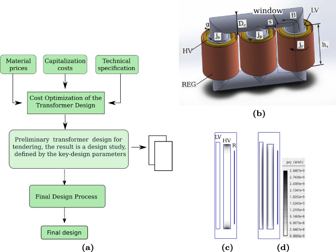
(a) Schematic view of transformer design process. (b) Key parameters of 3-phase core-type transformer. (c) Radial and (d) axial components of eddy loss density in transformer windings.
The majority of the published cost optimization methods consists in modelling the transformer only by the key-design parameters of its core and windings (Fig. 1b) [1]. These methods use a copper filling factor-based winding models to estimate the load loss of the transformer during the optimum search. This analytical formulation approximates the total amount of the load losses well, however, an accurate calculation of the eddy losses and temperature gradients is impossible from knowledge of the copper filling factor and the outline of the winding. Moreover, modern transformer windings are made of more than one winding material. It can be seen in Fig. 1c and Fig. 1d that the radial and axial distributions of the eddy current losses are non-homogeneous in the windings. The most critical part is the top of the HV winding, because it is heated by the radial component of the magnetic flux density and circulating oil is hot near to the top of the tank. To enhance the thermal and mechanical durability of the windings, these winding ends are usually made of different winding materials, and contain more parallel branches to minimize the perpendicular size of the conductors to the radial flux density [4].
This paper proposes a novel method, which uses a combination of two optimization methods: evolution algorithm (NSGA II) and generalized geometric programming (GP). The GP-based part of the optimization algorithm can determine the optimal conductor sizes automatically, from the shape, copper filling factor and other key-design parameters of the winding. Knowledge of the optimal conductor size allows applying a FEM calculation to calculate the eddy current losses, temperature gradients and short-circuit impedance more precisely during the optimization process. Moreover, the model can handle axially segmented windings.
The transformer optimization methodology has been realized in the Ārtap framework [5], which is an open-source tool for robust design optimization. In the realized methodology, every possible transformer design is represented as an individual. These individuals are defined by their seven independent parameters: current density of the windings (j s , j p , j r ), magnetic flux density (B), core diameter (D c ), height of the low voltage winding (h s ), and main gap distance (g) (Fig. 1b). Every other parameters of the applied transformer model can be determined by knowledge of the independent values and specification. The independent parameters are generated and optimized by the applied evolutionary algorithm (NSGA-II) as shown in Fig. 1a. The calculation of the dependent parameters is made in every iteration step, by the redefined evaluating function of the optimization framework. This calculation consists of three main calculation steps (Fig. 2a): the solution of the analytical model, FEM calculation and embedded geometric programming-based model. The analytical calculations consist of the determination of the geometrical parameters and calculation of the core losses [6]. The role of the FEM solution and geometric programming-based winding model is to determine the load losses, short-circuit impedance and temperature gradient for the new winding model. The paper extended with the temperature gradient calculation of the previously published FEM-based model [7]. The following section shows the objective function of the optimization and details of the new winding model.
Objective function – Total cost of ownership
The objective function is the total cost of ownership. This function contains the manufacturing cost of the active part and the cost of the calculated losses [6]:
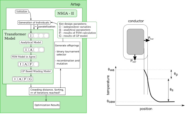
(a) Schematic view of the realized transformer design optimization algorithm. (b) Temperature notations around the winding-oil contact at approximately the half of winding height [8].
Transformer models in the pre-conceptional design phase model the geometry of the windings by their outer boundary and their copper filling factors [1]. So, the solution of these simplified pre-conceptional transformer models provides the optimal current density, load loss and optimal shape of the winding (see Fig. 1). This data is enough to calculate the magnetic field in the working window by FEM. The magnetic field in the working window of a transformer that is generally nonlinear may be described by the phasor
However, to calculate the eddy losses and the temperature gradients in the winding segments accurately needs to know the exact conductor dimensions and winding layout. If the optimal width (d∗) and height (h∗) of the conductor are known, the axial and radial parts of eddy current losses can be expressed by the following formulas [4]:
To calculate an optimal shape of the conductors, a geometric programming (GP) sub-problem is defined inside the evolutionary optimization sub-problem. GP is a type of the non-linear mathematical optimization problem characterized by the objective and constraint functions given in the following special form [9]:
The objective function of this embedded geometric program to minimize the loss of the winding:
The applied temperature gradient calculation uses an electrical analogy of heat exchange [8] to solve the 2D-Poisson equation of the steady-state heat flow, where the heat flow possible only in the axial or the radial direction (Fig. 2b) [8].
The heat-flow density value can be defined using the following formula, in case of disc-type windings, for the temperature rise calculation [8]:
Temperature gradient through the oil boundary layer, in the case of ON or OF cooling:
The gradient is defined by the following generalized posynomial:
The physical correctness of the transformer model has been validated by an existing 10 MVA, 33/6.9 kV, star/star connected transformer ([4], page 173–75). The detailed list of the transformer parameters presented in Table 1. The main dimensions of the working window (FEM model) and the resulting flux distribution are depicted in Fig. 3. The resulting value of the short-circuit impedance (SCI) from the finite element analysis is 7.52%, which is very close to the measured value (7.34%). The LV winding is made from 12 parallel conductors, whose thickness is 2.3 mm and the insulating paper thickness is 0.5 mm. The eddy current loss of this winding is calculated by the Rabins and Cogbill method and its value is 489.55 W [4]. The resulting winding dimensions after the GGP optimization differ from the manufactured transformer dimensions, the optimized conductor width is 1.7 mm. The dc loss of the offered winding system is 21.6 kW instead of the original 21.8 kW, and the eddy current loss after the calculation is 583 W. The GGP algorithm calculated 14 K for the temperature gradient.
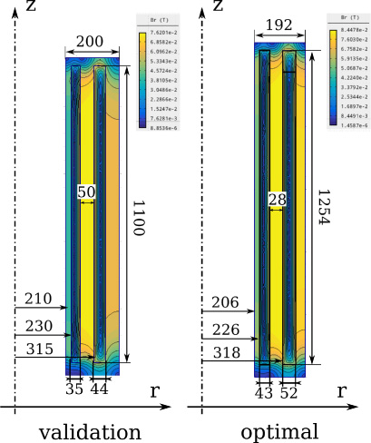
(c) Main dimensions and flux density distribution of validation example and optimization result.
Parameters of the optimized transformer
Resulted losses and key-design parameters
The transformer optimization was made for a solar power plant transformer design to illustrate the optimization method. The economic scenario and the capitalization factors selected from [10], where the capitalized cost of the load losses is k1 =1000 €/kW and the capitalized loss of the no-load losses is k2 = 7000 €/kW. The same technical data sheet, which was presented in Table 1, was used for this optimization. The NSGA-II algorithm generated 100 individuals for every 100 generations. The resultant geometry is depicted in Fig. 2 and the resulting main electrical parameters are listed in Table 2. The optimal transformer’s turn voltage is significantly smaller, than in the manufactured case. The smaller turn voltage means that the optimal design contains more steel and smaller amount of copper. This corresponds with the practice, that in the case of high ratio of k1∕k2 the transformer design with high load losses and small core losses leads to the economic optimum.
Conclusions
This paper proposed a novel transformer design optimization algorithm, which can determine the optimal conductor shapes for the transformer windings in the first design process. By the knowledge of the optimal conductor sizes, the thermal properties of a transformer can be considered at the beginning of the design for different winding layouts. The results of the transformer model were validated on a data of a manufactured 10 MVA transformer. Further research in the domain can use this method to examine the impact of the new biodegradable transformer oils on the key design parameters of large power transformers.