



Abstract
This paper presents an optimization method that deal with control techniques for electrical machines, in order to impose a displacement with a minimum of energy consumption. It’s a generic method; However, its application to electrical machines is complex for implementation. The present work provides the shape of the optimal solution. Moreover, a resolution technique related to the nature of the model is proposed, which facilitate the numerical resolution of costate problem. The method is applied to hybrid stepper motor and the obtained results are then analyzed.
Keywords
Introduction
The improvement of energetic efficiency of electrical machines is a field of study of high interest. In fact, the electrical consumption of electrical machines is about 46% of the total electrical consumption in the world. A 1% increase in energetic efficiency of electrical machines would save almost 80 million of kWh per year, nearly 14 million barrels of oil. Therefore, the energetic efficiency of machines is a crucial issue for the preservation of energetic resources, the environment and sustainable development [1,2].
Energy consumption problem of electrical machines could be formulated in three different ways. The first approach called, optimal design problem, consists in acting over the design of the machine and/or on the nature of materials in order to find the best design to reach the desired performances with the minimization of a certain criterion. In this case, dimensions and shapes evolve [3]. A second approach is to find optimal controls that ensure good performances while minimizing energy consumption subject to certain constraints. This is an optimal control problem. In this case, the main purpose is to find optimal control variables while dimensions are fixed [4]. Finally, it’s possible to simultaneously search for sizing and optimal control. This is the global optimization. In this sense, both dimensions and control are sought simultaneously. This approach leads to a more complex problem but more suitable for application [5].
Whatever the considered approach, there are usually two major difficulties. First, the problem should be correctly formulated by defining considered variables and the objective function. Then, the chosen optimization method should find the global minimum within an acceptable calculation time. Given that, the purpose is to conceive an electrical machine with an optimal control and design, the global optimization problem turns out to be the most interesting. However, multi-level approaches, which are widely used for this kind of problem could be inefficient because of their deterrent computation time [6]. That is why, to achieve our goal, it is necessary to adopt new methods that allows, both the integration of control parameters and the design optimization with better computation time. In this paper, we herein propose a realistic model of an electrical motor, and then we formulated an optimal control problem with the willing to propose a global optimum.
The optimal control theory is a branch of variation calculation. It appeared after the Second World War to solve practical problems especially in the field of aeronautic. The key of this theory is the Pontryagin’s Maximum Principle, PMP, introduced by L. S. Pontryagin in 1956. The PMP provides a necessary condition for optimality and allows the calculation of optimal trajectories [7,8]. This theory is applied in various fields. e.g. in [9], the PMP is used to solve problems of orbital transfer. In [10] and [11], the control theory is applied to find strategies of energetic optimization of hybrid electrical vehicles. Investigations in [12] used the theory in order to find an optimal control strategy that minimizes the flux of power in a small electrical network. However, applying optimal control theories on electromagnetic devices is not frequent, because of devices models that are often complex and non-linear [13]. Nevertheless, some investigations get interested on the application of the PMP for the study of electrical machines, with using first order machine models. In [4], e.g. a position control algorithm is developed while minimizing time and energy of an induction motor.
The present work applied the theory of optimal control on a magnetodynamic model based on a reluctance network model of a hybrid stepper motor, HSM. The main purpose is to move the load to a certain position while minimizing energy. HSM motors are characterized by a tridimensional distribution of flux. The rotor corporates a permanent magnet axially magnetized and magnetic teeth. The stator carries the winding and has small teeth at the periphery of the bore. Varieties of models of HSM were developed in many researches. In [14], Matsui and al elaborated one of the first examples of models. These models are based on an equivalent magnetic circuit composed of permeances for the air gap, magneto mortice forces for the coils and of the magnet. The model is an entirely analytical and the relative permeability of iron is assumed infinite. Kang and Lieu [15] presented another approach. In their research, they calculated the air gap permeances using the 2D finite elements method. A deeper study was presented by Kuet and al in [16], were the elaborated magnetic model take in account the saturation phenomena and the leakage flux. From 2002, advances on the numerical calculations have made the study of 3D finite of complex structures possible. In [17], Koasaka and al, presented a 3D finite elements model of an HSM. Investigation in [18] by Stuebig and Ponick proposes a comparison between different modeling methods.
The model of electrical machine used in the present study is based on Matsui and al [14] work, with an improvement of the accuracy of air gap permeances calculation. The model choice is built over its compromise between the accuracy and calculation time.
The paper is organized as follows; Section 2 presents the chosen model structure under the form of state variable. In Section 3, the PMP is applied to find the optimal control profile that minimizes the necessary energy for displacement. A classical control obtained with an optimization on a step is illustrated in Section 4. Finally, the last section is dedicated to compare and analyze obtained results of two controls.
Modeling
Figure 1 illustrates a section of the hybrid stepper motor structure. It presents 8 powered stator’s plot and has two phases 𝛼 and 𝛽. Each stud has 6 small teeth. The rotor is composed of two rings; each one has fifty teeth and are connected between them by a permanent magnet. The flux path is then tridimensional in the rotor.
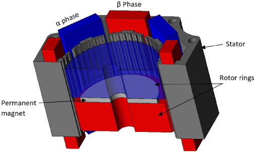
Structure of the hybrid stepper motor.
A 3D magnetic model of reluctance network was developed in [17]. This model computes inductances L𝛼(θ) and L𝛽(θ), flux φ𝛼(θ) and φ𝛽(θ) provided by the magnet. These values are calculated for each mechanical position of the rotor θ depending of dimensions and machine’s parameters. These values are injected in the electrical equations, in order to determine phases currents I𝛼(t) and I𝛽(t). The electromagnetic torque C em (t) is deduced and is applied further in the magnetic model. Figure 2 shows the magnetodynamic global model and relations between models. This model is parametrized and contains the coupling of 3 physics: electrical, magnetic and mechanical. With l m : length of the magnet (m), l r : length of a rotor ring (m), g: gap length (m), t w : tooth width (m), N s : number of turns, N t : number of tooth, and H C : coercive field of the magnet (A/m). θ(rd): electric angle, k fv : viscous friction coefficient, J: inertia of the system (kg⋅m2).
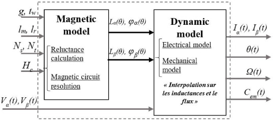
Electromechanical model of the stepper motor.
Thus, the dynamic model of the device could be expressed as in (1):
Optimization problem
Starting from an initial position θ0, a final position θ
f
should be reached with a final speed 𝛺
f
in an instant T. This displacement has to be operated with the minimum of energy. The problem is therefore given by ((2)).
The Hamiltonian of system (1) is given by:
According to the problem formulation, the optimal control must minimize the Hamiltonian of the system. Thus, we should study the variation of the Hamiltonian with respect to each control, and then we pass through the derivative of H according to each control, as HV 𝛼 and HV 𝛽.
Equations (7) and (8) are called switching functions that switch according to costate variables. These types of controls are called bang-off-bang controls, while they assume values only in the boundary points of the control interval. This result is interesting for the study of electrical machines. In fact, we firstly proved that for minimizing the energetic consumption, we must deal with bang-off-bang controls. In a second row, this result is obtained after explicitly expressing the control, considering parameters in Fig. 2.
Equations (1), (4), (7) and (8) gather the Hamiltonian model composed of the costate model (9) and of the state model (10). The link between the two models is obtained with the control, expressed in (7) and (8). We must emphasize here that one of the drawbacks of this method is the heaviness of the analytical calculations.

Resolution process with the Hamiltonian model.
The method is applied on a small hybrid stepper motor of 200 steps per spin (1 step = 0.0314 rd). The machine is at standstill and must drive a load, reach a position with an accuracy of 10−4 rd, in this example, the angle 0.6776 rd and must be at standstill in 1.3 s. The problem resolution takes about 10 min with an ordinary computer. Graphs in Figs 4 and 5 illustrate respectively, the obtained optimal control
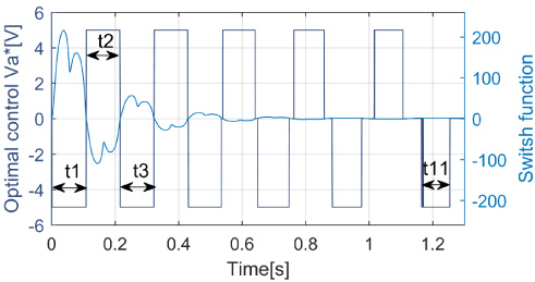
Optimal control
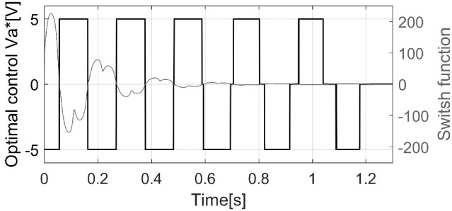
Optimal control
The optimal control generated is a bang-off-bang control with different pulse widths that decrease progressively until reaching the desired final position. In Table 1 different widths values of positive and negative pulse of the control
Pulse width
The motor makes approximately 21 to 22 steps. This optimal number of steps and optimal phase switching are generated automatically.
Figure 6 shows the rotation speed and the evolution of the mechanical angle.

Evolution of rotation speed and mechanical angle.
After the start-up, the speed varies between 0.67 rd/s and 0.33 rd/s, the switches of phases and the evolution of steps cause the drops of speed. The mean speed over a step increases progressively during the first 13 steps then drops to be equal to zero on the final position. This behavior is caused by the inertia effect that exert a high impact on the energy consumption. Thanks to the inertia, the motor needs less and less energy to reach the final position, which elucidate the decrease of pulse widths, given in Table 1 and the shape of the evolution of the position that illustrates a curvature.
Figure 7 outlines the evolution of costate variables 𝜓1(t) and 𝜓2(t), respectively related to currents I𝛼(t) and I𝛽(t). We naturally find the same shapes and the same phase shift as the switching functions with a difference in amplitudes due to à 1∕L𝛼 and 1∕L𝛽 beta (5), (6).

Costate variables 𝜓1(t) and 𝜓2(t).
Figure 8 illustrates the evolution of the costate variables 𝜓3(t) and 𝜓4(t) related to the speed 𝛺(t) and the position θ(t), respectively.
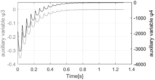
Costate variables 𝜓3(t) and 𝜓4(t).
Figure 9 shows the evolution of the currents I𝛼(t) and I𝛽(t).
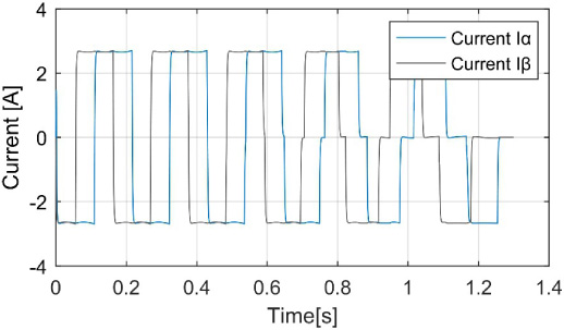
Evolution of the excitation current.
A dichotomy method applied to the costate variable according to the position 𝜓4(t0) enable reaching rapidly the desired position with respect to the accuracy. This method is fast, easy to apply and avoids problem of convergence of the shooting method. Figure 10 depicts the functions of switch and the evolution of the mechanical angle for different values of 𝜓4(t0).
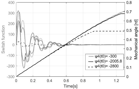
Switch function and mechanical angle for different value of 𝜓4(t0).
The method of dichotomy on the initial value of 𝜓4(t0) enable the settle of the accuracy on the final value of the position. In our considered example, for a value of 𝜓4(t0) = −2005.8 allows reaching the final position of 0.6776 rd with accuracy and less iteration.
The purpose is to compare the obtained results with the PMP to a classical control. In the case of a classical control, pulse widths are unchanged. To find a classical control that enable reaching the desired position with a minimum of energy, we proceed by using time-scaling method [19]:
We consider x1 the width of each pulse, for the two controls, and x2 (resp. x3) the width of the last pulse of the control V𝛼(t) (resp. V𝛽(t)). We aim to find x1, x2, and x3 which allow us to achieve an angle 0.6776 rd and to standstill in 1.3 s with the minimum of energy. The problem could be formulated as in ((13)):
The used solver is the fmincon function of Matlab® with the algorithm SQP. The pulse widths obtained by optimization are given in Table 2.
Pulse widths
Figure 11 shows the classical controls V𝛼(t) and V𝛽(t) obtained with the optimization by ((13)).
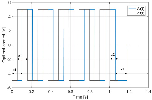
Classic optimal control.
In Fig. 12 are illustrated the rotation speed and the evolution of the mechanical angle for the two types of control.

Evolution of rotation speed and mechanical angle for both methods.
The classic control enables reaching the position faster with a more regular speed evolution. Figure 13 presents the evolution of the voltages sum at each time instant for the two cases of control. The value evolve between 2Vmax and Vmax for the control obtained by the PMP, while for the classic control, the value stand constant at 2Vmax at each step from the start, thus each step consumes the same amount of energy.

Evolution of objective function.
As shown in Fig. 14 of the evolution of the power developed by the two controls, we notice the effect of the inertia and the gradually decrease of the power consumption for the optimal control. The machine develops then the minimum of torque necessary for driving the load to the final position. Figure 15 represents the electromagnetic torque obtained for the two types of controls. For the classic control the same torque is developed for each step, whereas, for the optimal control the torque decreases progressively.

Evolution of input power.

Evolution of electromagnetic torque.
Table 2 introduces a comparison between the energetic performances of the HSM for the types of control.
Energetic performance comparison for the classic control and optimal control
The optimal control obtained with the PMP offered a gain of 5.7% compared to the classical control for the studied problem.
In this paper, we proposed the application of the Pontryagin’s maximum principle of to a magneto-dynamic model based on a reluctance network of a hybrid stepper motor. The main purpose was to find an optimal control that minimizes the energy. The applying of PMP enable to express explicitly the control according to the parameters of the model and to have a Hamiltonian model that generates automatically an optimal control. The study has showed that the problem of sensitivity to the initial conditions encountered at the resolution of the Hamiltonian model could be solved by a simple dichotomy when it comes to the control problem of an electrical machine. The presented results showed a gain of 5.7% compared to a classic method thanks to the effect of inertia that has an important impact on the energy consumption and that is present in all the electrical systems.