
Abstract
This paper presents the electromagnetic and mechanical analysis of an axial flux permanent magnet (AFPM) motor for high speed (12000 rpm) rotor which is vertically suspended by magnetic bearings. In the analysis, a prototype AFPM motor with a double-sided rotor and a coreless stator between the rotors are considered. Firstly, electromagnetic analysis of the motor is carried out by using magnetic equivalent circuit method. Then, the rotor disk thickness is determined based on a rotor axial displacement due to the attractive force between the permanent magnets placed on opposite rotor disks. Hereafter, an analytical solution is carried out to determine the natural frequencies of the rotor-shaft system. Finally, 3D finite element analysis (FEA) is carried out to verify the analytical results and some experimental results are given to verify the analytical and numerical results and prove the stable high-speed operation.
Keywords
Introduction
In the last two decades, studies about AFPM machines have intensified due to their most highlighted advantages: high power density, high efficiency and high torque-to-volume ratio. The compact and robust structure of the AFPM machines makes them very suitable for electrical energy generating applications. Especially, those working at low speeds are widely used in wind energy applications, flywheel energy storage systems (FESS) and electrical vehicles [1–6].
With suspending the AFPM motor by magnetic bearings, the friction between contacted surfaces is removed, so, bearing and thermal losses at high speeds are significantly reduced. Moreover, the AFPM motor is enabled to operate at very high speed due to non-contact bearings, with the option of being used for direct drive applications. With eliminating gear mechanism would lead to reduced transmission losses that bring high-power density and higher efficiency [7–10].
There are very small airgaps between the stator and permanent magnets (PMs) mounted on the rotor disks that produce a very high attractive force between the PMs on opposite rotor disks. These forces may cause to bend rotor disks from the outer edges. Since the rotor disks of the motor represent around 60% of the total active mass of the machine, the mechanical design of such a machine should carefully be reviewed. Power to weight ratio of AFPM machine can be increased by optimizing the rotor disk thickness. Mueller et al. investigated the inactive mass in the design of AFPM machines for direct-drive low-speed wind turbines [6]. Fei et al. studied a mechanical analysis and design optimization of the rotor discs for a high-speed air-cored AFPM generator; however mechanical vibrations of the machine were not considered [7,8]. Sadeghierad et al. presented designing procedure of back-iron thickness of the AFPM generator considering the optimization of terminal voltage, output power, and efficiency [9]. Kumar et al. investigated the sinusoidal back EMF considering the mechanical stress analysis for an AFPM machine for high-speed energy storage application. So far, most studies focus on the analysis and design for AFPM machines from the point of view of electromagnetic aspects. Although some examined studies have addressed mechanical issues, they are dealt with as supplementary to the electro-magnetic design and most of them are considered for low-speed applications [11–18].
This study contributes a systematic analysis and design methodology for an AFPM motor with a double-sided rotor and a coreless stator between the rotors from the point view of estimating mechanical stress resulted from the electromagnetic origin for high-speed operations. A unique structure is proposed for the AFPM machine suspension that integrated with radial and axial magnetic bearings allowing the rotor to reach high-speeds. Hence, employing such configuration for high-speed flywheel energy storage systems supported by magnetic bearings may eliminate flywheel disk and twin-rotor disks of the AFPM can function as flywheel disk. If it is mentioned that the motor rotates at high speed, the vibration modes that will occur should also be examined. However, there is almost no study on this subject for AFPM in the literature; we carried out a detailed analysis on this issue. While the design provides a considerable shortening of axial length of shaft when compared with the horizontally suspended counterparts; it also increases the gyroscopic rate and reduces the gyroscopic effects that may occur at high speeds.
The paper is organized as following; at first, electromagnetic analysis methodology using magnetic equivalent circuit approach is outlined. The same model used in electromagnetic analysis is also utilized in 3-D finite element analysis to verify correctness of the analytical results of magnetic equivalent method approach. Then, mechanical stress and vibration analysis of the AFPM are performed by using electromagnetic analysis results. Effectiveness of the analytical approach is confirmed by 3-D finite element analysis both mechanical stress and vibration analysis. At last, the constructed prototype is operated at high-speeds, the simulation results are verified by performing the hammer test of the rotor and examining the mechanical vibration values at high speeds.
Electromagnetic and structural analysis
The AFPM motor considered in this study has double-sided rotor disks with a coreless stator between them. Figure 1 show the produced rotor disk and stator before assembled. The coreless stator coils are housed in a non-magnetic epoxy-resin plate. The rotor disks are constructed from structural steel and PMs are mounted on them. The dimensions of the constructed prototype are also given in Fig. 1.
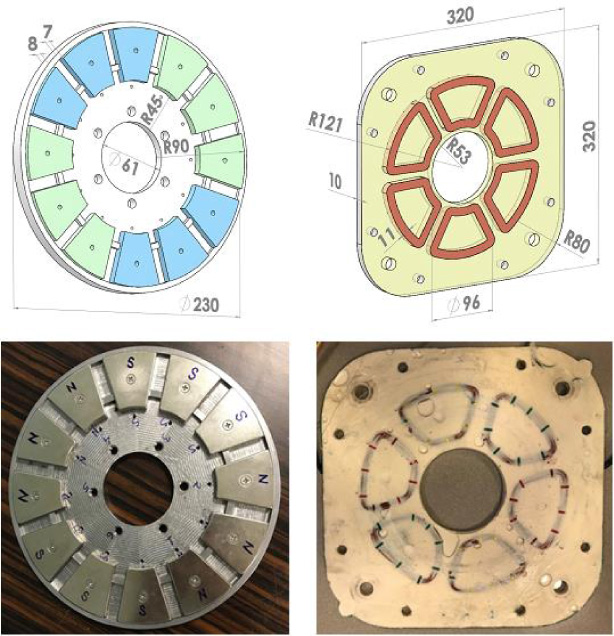
Prototype AFPM motor: one of the rotor disks with PMs (left), Stator (right).
Double sided rotor with internal coreless stator topology used for low and medium power generators and have various advantages, including the absence of cogging torque, as well as their linear torque – current characteristics, high power density, and compact construction [11,12,16,19–21]. Also, by removing the core losses, this type of generator has a higher efficiency compared to the conventional generators. Considering the number of poles should be low to reach high speeds, it is decided to design the motor with 2 pole pairs. The coils in the stator are designed with a single layer concentrate winding form with 15 turns per coil. After assembling the AFPM motor, the rotor disks are integrated with a shaft suspended by magnetic bearings both radial and axial directions. The total system is shown in Fig. 2.

AFPM motor vertically suspended by magnetic bearings.
The magnetic equivalent circuit for a pole associated with the motor topology is shown in Fig. 3. In this circuit, R
gap
, R
PM
, R
lk
and E
PM
are the air-gap reluctance, the permanent magnet reluctance, the leakage flux path reluctance and magneto motive force due to coercivity of the PMs, respectively. The flux travels axially from one rotor disc to the other and completes its path by returning circumferentially around the rotor disc to the next magnet. We can define the flux by assuming that all reluctance are collected by R
total
;
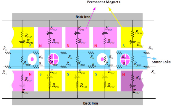
Magnetic equivalent circuit of the AFPM for a specified pole cross section.

Magnetic flux density distribution in the air-gap of the AFPM. (a) FEM representation of the flux profile for the specified pole region. (b) Magnetic flux distribution motor structure.
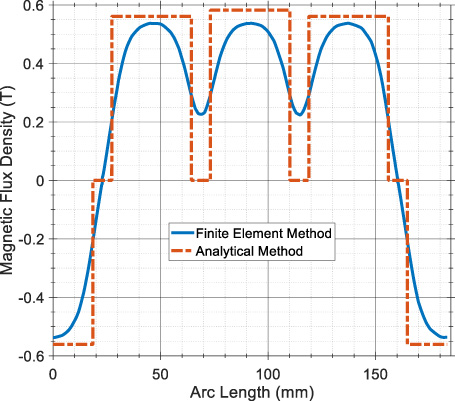
The magnetic flux density profile through a specified pole cross section.
The rotor disks of the motor are constructed of two 8 mm-thick steel disks with 7 mm-thick permanent magnets which represent around 60% of the total active weight of the machine. Here, to determine the thickness of the rotor disks, bending values are examined as a result of the attraction forces between the magnets. Well-known analysis of magnetic equivalent circuits can be used to determine the airgap flux density and hence the Maxwell stress is given by
Magnetic flux density vs. airgap curve was calculated using ANSYS Maxwell to decide the air gap between stator and PM’s mounted on rotor discs. In the literature, the magnetic flux density value is found around 0.6 T for similar sizes AFPM’s. Then it is decided that the operating airgap point should be 2 mm on both sides when the mechanical limits are considered, as can be seen from the Fig. 6.

Magnetic flux density vs. airgap between the opposite poles.
Hereafter, Fig. 7 shows the attraction force value if a distance of 15 mm is found between opposite magnets; the difference between the results doesn’t exceed 10%. Although the difference between the results is minimal at the nominal operating point, the error increases due to flux leakages that is considered in FEA. So that, FEA results are taken into account to see the magnetic pull force which corresponds to a magnitude of 500 N per magnet and a total of 12 magnets which corresponds to 6000 N. These values will be used to find deflection and stress results of different thickness rotor discs.

Magnetic attraction force between the opposite magnets.
In order to calculate the bending and stress values, the rotor disk with geometric details is first modeled analytically. Circular plate theory can be used to model the rotor disk as a flat circular plate of constant thickness with its outer edge free and the inner edge fixed. The geometrical details of the rotor-magnets system can be seen in Fig. 1. Circular plate equation is written as follows by taking the center of the plate in polar coordinates [23]:
For a three-disk rotor-disk system, the equations of motion in matrix form can be written as:
Numerical analysis
In this section, a comparison between analytical model results and FEA will be explained. In order to verify the analytical results, finite element analyses are performed by using Modal and Structural Analysis sections of ANSYS Workbench; electromagnetic force analysis is performed by using ANSYS Maxwell. Electromagnetic and mechanical properties of the materials used in FEA is tabulated in Table 1. The analytical approach of electromagnetic analysis based on magnetic equivalent modelling of machine components is developed by considering flux leakage effect between adjacent poles. The model is quite simple and logical to determine the air gap flux density of the machine. It is found that flux distribution shape is identical and amplitude values compatible. As can be seen in Fig. 5, the highest flux amplitude error is less than 10%. Hereafter, the electromagnetic force and mechanical stress analysis results are demonstrated. Figure 7 shows the attraction force analyses between the rotor disks. The result of this analysis is used in structural analysis. To simplify the analysis it is assumed that the stress q spread across the area of the magnet. The Maxwell stress is thus modified by multiplying it by the magnet cross-sectional area, so that the overall force acting on the rotor disk remains constant.
Mechanical properties of the materials used in FEA
Mechanical properties of the materials used in FEA
Since the attractive forces of PMs are high and the airgap between the stator and rotor disks are small, the deflection of the rotor disks must be limited to prevent contact PMs from stator surface. The results of the mechanical stress analysis for different rotor thickness values are tabulated in Table 2. Considering maximum allowable stress for the used material and assuming that the motor will operated at reasonably constant environment conditions subjected to load and stresses that can be determined readily, the safety factor of 2 is selected and 8 mm thickness value is determined for the rotor disks. Analytical solution is carried out only for 8 mm thickness value. Figures 8 and 9 show the stress and bending values obtained as a result of the analysis. The comparative results of the mechanical stress analysis comply with each other and show that the bending values of the outer edges of rotor disks are much lower than the critical limits.
Mechanical stress analysis comparison
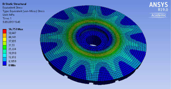
Stress analysis of rotor disk using FEA.

Deformation analysis of rotor disk using FEA.
Then, rotor mechanical vibration analysis is carried out; conical, bending and torsional vibration modes can be seen in Fig. 10. In the vibration analysis of the rotor, the radial magnetic bearing points are assumed to have stiffness value of 1000 N/mm. In addition, the axial magnetic bearing point is considered as fixed point assuming that the rotor does not move axial direction. While the mechanical design is performed, it is assumed that the shaft will rotate at a speed of 12000 rpm. As seen from the analysis results, given in Table 3, the results obtained by the analytical method and the results of numerical analysis overlap each other. In addition, it is sufficient as a design parameter that the 1st and 2nd conical mode is lower than the rotational speed of the rotor. Because rotor can be accelerated as fast enough to pass these critical frequencies and operating speed is far away from the 1st bending mode.
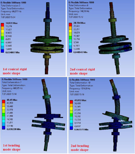
Vibration mode shapes of the shaft using FEA.
Natural frequency analysis comparison
A prototype motor has been produced and integrated into the magnetic bearing system which shown in Fig. 11. The motor can be directly drive by using the AB50A200I AxCent TM panel mount servo drives that are targeted for centralized control and offers high bandwidth and quick response times. The AB50A200I features built-in isolation between high and low power signals. Motor speed can be controlled by a closed-loop system. The PC sends analog control signals (via MicroLabBox) produced by drive logic based on hall-effect sensors’ feedback. The motor has been tested under the no-load condition and mid-speed increases over 6000 rpm with the input power at 2.7 kW which shown in Fig. 12. The test has been repeated several times to operate the rotor with varying rates of acceleration and deceleration. In addition, the motor was operated at maximum speed for 2 hours; thus, it has been confirmed that the rotor is mechanically robust. Also, hammer test is applied to the rotor using Bruel & Kjaer equipment, the results of which are shown in Fig. 13. Both analytical and FEA results verified via hammer test results that there is no vibration mode frequency near the operating speed which can be interpreted as shaft can be rotated safely.
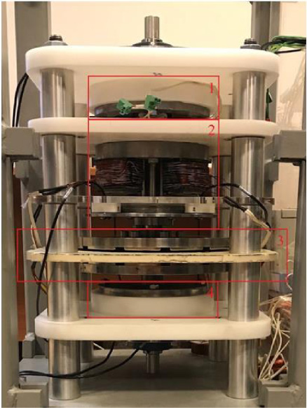
Experimental setup (1 – Upper RMB, 2 – Axial HMB and Thrust disk, 3 – AFPM Rotor disks and Stator, 4 – Lower RMB).
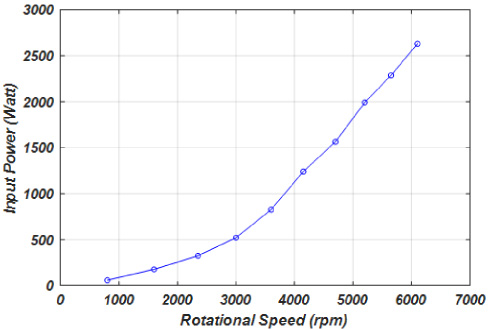
Variation of the input power versus speed.
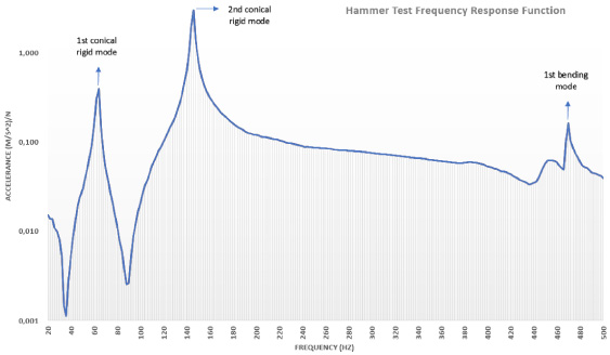
Hammer test frequency response function graph.
Since it has the advantage of disregarding necessity of flywheel in a FESS an AFPM may have great potential usage in such systems. Moreover, it may eliminate attraction force between the stator and rotor core due to non-ferromagnetic core usage possibility leading to a coreless structure. In this paper, to exploit the outlined advantages of AFPM machines electromagnetic, mechanical stress and vibration analysis were presented. The analytical approach of electromagnetic analysis based on magnetic equivalent modelling of machine components was developed by considering flux leakage effect between adjacent poles. The model is quite simple and logical to determine the air gap flux density of the machine. The effectiveness of the magnetic equivalent model is tested by a comparative study of 3-D FEM analysis of the same model. For the mechanical stress and vibration analysis, an analytical model employing the findings of electromagnetic analysis (especially attraction force between the rotor disks and sizing of rotor disks) was developed. Furthermore, to validate the effectiveness of the analytical approach of mechanical stress and vibration analysis, for the same model a series of 3-D FEM analyses were carried out. It was seen that the discrepancy between analytical model and FEM analysis can be negligible since it is less than 8%. The approach followed by the paper is effective and systematic to analyze electromagnetic and mechanical properties of the AFPM for possible use in FESS supported by magnetic bearing. In addition, models developed for electromagnetic and mechanical analysis can be used safely in the dimensioning and optimization of AFPM machines for high-speed operations.
Footnotes
Acknowledgements
This work is supported by the Scientific and Technological Research Council of Turkey under Project 217M073.