
Abstract
This paper proposes a novel flux switching claw pole machine (FSCPM) with soft magnetic composite (SMC) cores. The proposed FSCPM holds advantages of the conventional flux switching permanent magnet machine (FSPMM) and claw pole machine (CPM) with SMC cores. As permanent magnets are installed between the stator claw pole teeth, FSCPM has good flux concentrating ability, and the air gap flux density can be significantly improved. The torque coefficient of FSCPM is relatively high due to the applied claw pole teeth and global winding. FSCPM is mechanically robust because there are no windings or PMs on its rotor. Moreover, the core loss of FSCPM is relatively low for the SMC material has lower core loss at high frequency compared with silicon steels. The topology and operational principle of FSCPM are explained first. Several main dimensions of the machine are optimized to achieve better performance, based on 3D finite element method (FEM). Furthermore, the rotor skewing technology is adopted to reduce the cogging torque and torque ripple.
Keywords
Introduction
Due to the merits of high torque ability and robust mechanical structure, flux switching permanent magnet machine (FSPMM), as a relatively new type of permanent magnet (PM) machine, has been used in many high-performance applications, including electric vehicles [1–4]. Extensive research work has been done to improve the performance of FSPMMs. C-core, E-core, multi-tooth stator core have been investigated to improve the torque coefficient and reduce the torque ripple. Hybrid excitation configuration has been presented to improve its constant power range speed, and multi-phase structure has been proposed to improve its fault tolerant ability [5–10]. Moreover, various optimization methods, like system level and multilevel optimization methods [11], have been employed to maximize the output power (or average torque) and minimize the torque ripple for different applications, including electric vehicles [12–15].
Claw pole machine (CPM) is a special kind of transverse flux machine (TFM). Compared with TFM, CPM can have higher torque ability and power factor, as the adopted claw pole teeth can help CPM use more PM fluxes and reduce the flux leakage [16]. However, CPM has a complex structure, which makes it difficult for manufacturing. With the development of soft magnetic composite (SMC) material, the manufacturing process of CPM with SMC cores can be much easier by using molding technology, for example, by using a hot press [17–20]. SMC material is a relatively new kind of soft magnetic materials. With the small iron particle enclosed by insulation layer, SMC material can have a great number of advantages when compared with the other traditional soft magnet materials, e.g. silicon steels. Firstly, the core loss of SMC material at high frequency is very low. Secondly, SMC material has the advantages of magnetic and thermal isotropy. Thirdly, the production cost of the SMC cores is low by using molding technology in batch production [21]. In the past decades, the performance of SMC material has been improved greatly. Various kinds of electromagnetic devices with SMC cores have been developed [22–26]. In the design of electrical machines with SMC cores, some useful guidelines have been concluded. In many situations, the machines need to be designed with 3-D magnetic flux, high operation frequency and PM excitation [16]. Furthermore, many design optimization models and methods, like robust design optimization, have been investigated to achieve high manufacture quality of PM motors by using low cost of SMC cores, which can improve the industry application of this kind of motor [27–29].
In this paper, to make full use of the merits and structure characteristic of both CPM and FSPMM, a novel flux switching claw pole machine (FSCPM) with SMC cores is proposed. The proposed FSCPM can have high torque ability due to the following reasons. First, the 3D magnetic flux and global winding bring the machine with high torque coefficient and the special PM structure can form good flux concentration structure to improve the air gap flux density. Second, the FSCPM can be operated robustly as there are no windings or PMs on the rotor. Third, the efficiency of FSCPM can be high as the SMC material has lower core loss at high frequency.
The structure of this paper is organized as follows. Section 2 describes the topology and operational principle of FSCPM. Section 3 presents the finite element analysis for FSCPM. 3D finite element model (FEM) is used for the parameter calculation and performance analysis in this paper. Section 4 investigates the optimization of the main parameters in FSCPM. Parameter and performance analysis of FSCPM are conducted in Sections 5 and 6, respectively. In Section 7, the cogging torque and torque ripple of FSCPM are reduced by using the rotor skewing method, followed by the conclusion.

Topology of FSCPM (single phase).
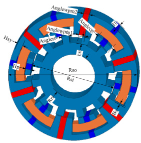
The main electromagnetic structure of a single phase FSCPM is illustrated in Fig. 1. The complete FSCPM is composed of three single phase modules arranged along axial direction. Each module is shifted with a determined degree to form symmetrical three phase operation. It can be seen that all the PMs and winding are placed on the stator, and there are no windings or PMs on the rotor. The PMs are inserted in between of stator claw pole teeth, and all the PMs are magnetized along the circumferential direction. Moreover, the adjacent PMs are magnetized along the opposite direction. The number of PMs is equal to the number of rotor poles. Different from traditional CPM, the number of pole pairs of FSCPM equals to the number of poles, which will make the operational frequency of FSCPM two times higher than that of traditional CPM with the same number of stator claw poles.

Operational principle of FSCPM, (a) main magnetic flux path at 0 degree, (b) main magnetic flux path at 7.5 degrees, (c) main magnetic flux path at 15 degrees, (d) main magnetic flux path at 22.5 degrees, and (e) PM flux linkage of FSCPM at different rotor positions.
For the single phase FSCPM, its operational principle is similar to that of a single phase FSPMM. The main difference is that the magnetic flux path of FSCPM is more complex. The PM flux path of a FSCPM at four typical rotor positions is illustrated in Fig. 2. As shown in Fig. 2(a), the PM flux starts from PMs then enters into stator claw pole teeth and arrives at rotor pole via air gap. The PM flux will go back to PM through rotor yoke, rotor pole, air gap and stator claw pole teeth on the adjacent side, and thus to form a closed loop. As the main PM flux will not enter stator yoke, there is no PM flux that the winding can be linked. Thus, the PM flux is zero at this position. In Fig. 2(b), starting from PM, the PM flux enters into stator yoke and through stator wall and stator claw pole teeth, then it will arrive at rotor pole via air gap. After that, it passes rotor yoke to go to adjacent rotor pole and arrives at adjacent stator claw pole teeth, stator wall and stator yoke, and then goes back to the PM via the air gap. At this position, the PM flux can be linked by the winding, and thus the PM flux for the winding can achieve maximum. Figures 2(c) and (d) show the PM flux of FSCPM at the other two typical rotor positions. Figure 2(e) shows the PM flux linkage waveform of FSCPM with the variation of rotor positions. It can be seen that the PM flux linkage of FSCPM is zero when the main PM flux does not pass the stator yoke.
Main dimensions of FSCPM.
Figure 3 shows the main dimensions of FSCPM. The electromagnetic torque of FSCPM can be expressed as
Based on (1), when the following conditions are met,
In this paper, the outer dimensions of FSCPM are the same as those of the CPM with SMC core discussed in [15], where the outer radius of stator equals 33.5 mm, and effective axial length for per stack is 18.2 mm. To ensure that the PM and stator claw pole can have enough mechanical strength, the thicknesses of stator yoke, stator claw pole and magnet are designed as 3 mm. Therefore, the initial thickness of stator wall can be calculated as 4.55 mm, and outer radius of stator core can be calculated as 13.75 mm, depending on above equations.
Considering that the permeability of SMC material is not very high, generally lower than 700, and the magnetic flux path of FSCPM is very complex, 3D FEM is an effective way to obtain accurate magnetic parameters and performance. In this paper, the commercial FEM software MAXWELL 3D is adopted for the FEM analysis. The mesh of FSCPM is shown in Fig. 4.
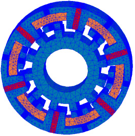
A mesh of FSCPM.
Figure 5 shows the no load flux density distributions of FSCPM at four typical rotor positions. It can be seen that the no load magnetic flux density distributed on the stator claw pole teeth is very high and it is close to 1.5 T as the adopted good flux concentration structure.

Typical no load flux density distributions of FSCPM at different rotor positions, (a) 0 degree, (b) 7.5 degrees, (c) 15 degrees, and (d) 22.5 degrees.

Air gap flux density of FSCPM at four typical rotor positions.
As shown in Fig. 2(a), at the rotor position of 0 degree, the flux density on the right claw pole wall equals that on the left claw pole wall. As the main magnetic flux path will form a closed loop through the stator claw pole, air gap and rotor core, the main PM flux will not enter the stator yoke, as shown in Fig. 5(a). At the rotor position of 7.5 degrees, the flux density on the left claw pole wall is lower than that of right claw pole, the main PM flux will form a closed loop through the right claw pole teeth, stator yoke, and the claw pole teeth on the other side with the rotor cores, as shown in Fig. 5(b). At the rotor position of 15 degrees, the flux density on the left claw pole equals that of right claw pole as shown in Fig. 5(c). At the rotor position of 22.5 degrees, the flux density on the left claw pole wall is higher than that of right claw pole wall. Figure 6 illustrates the air gap flux density distribution of FSCPM. As shown, the air gap flux density is about 0.75 T. It can be seen that the effective air gap flux density under the stator claw pole is nearly the half as that in a conventional CPM. Thus, the PM flux linkage of the FSCPM will be lower than that of a conventional CPM.

Motor performance in terms of stator inner radius and stator wall thickness, (a) torque, and (b) core loss.
This section investigates an optimization procedure to improve the performance of the proposed FSCPM. Considering that the used magnetic material is nonlinear and the complex magnetic flux path of FSCPM, 3D FEM is used to optimize several main dimensions. The stator inner radius and thickness of stator wall are critical to the motor performance, as they balance the magnetic load and electric load. By using the deduced torque equations, the initial values of these two parameters can be obtained. Then, combined with our design experience on CPM with SMC cores, the optimization region of the stator inner radius can be determined, i.e. from 20 mm to 23 mm. Similarly, the optimization region of the thickness of stator wall is determined from 4 mm to 7 mm. Figure 7 illustrates the torque and core loss of FSCPM with these design parameters. As shown, the torque decreases with the increase of thickness of stator wall, and the torque will reach its minimum when the stator inner radius equals 22.5 mm. As for the core loss, it decreases with the increase of stator inner radius and stator wall thickness. For the overall consideration, the stator inner radius and wall thickness are chosen as 22 and 4 mm, respectively.
Main parameters and dimension of the proposed FSCPM
Main parameters and dimension of the proposed FSCPM
In the PM machine, the thickness of PM is a very important parameter because it determines the load line of PM. In the proposed FSCPM, the thickness of PM is optimized as well. The parameter of anglepm1 is defined as the angle of PM close to the inner stator radius. It is close to the inner radius of stator core, and it will balance the stator claw pole teeth and PM. If it is too large, the space for the stator claw pole teeth will be narrowed, and if it is too small, PMs cannot produce enough magnetic strength for the FSPMM. Figure 8 shows the torque and core loss variations in terms of anglepm1 and anglepm2, where anglepm2 defined as the angle of PM close to the outer stator radius as illustrated in Fig. 3. Considering that the constrict of machine structure, the optimal region of anglepm1 is selected from 5 to 8 degrees, and that of anglepm2 is selected from 3 to 8 degrees. It can be seen that the EM torque of FSCPM can be achieved when the anglepm1 equals 8 degrees and anglepm2 equals 4 degrees. However, for the overall consideration, the final anglepm2 is determined as 5 degrees for achieving lower core loss. After this optimization procedure, Table 1 tabulates the main parameters and dimension of the proposed FSCPM.
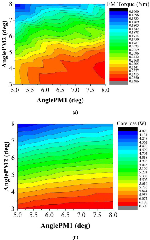
Motor performance in terms of permanent magnet parameters, (a) torque, and (b) core loss.
The PM flux per turn of FSCPM is obtained by using the 3D FEM, as shown in Fig. 9. It can be seen that the amplitude of PM flux linkage per turn is about 0.14 mWb. A whole electric period is 30 degrees, which can be used to verify the above theoretical analysis results. When the rotor is rotated at speed of 1800 rpm, the back electromotive force (EMF) per winding of FSCPM can be calculated, as shown in Fig. 10. It can be seen that the waveform of the back EMF is close to sinusoidal waveform and its magnitude is about 20 V. However, it has a great number of high order harmonics as illustrated in Fig. 10(b). Figure 11 shows the calculated inductance with the variation of rotor positions. As shown, the variation of inductance at the different rotor positions is not too larger. The average inductance is about 0.8 μH. Due to the difference of d-axis inductance and q-axis inductance is not big, the condition of d-axis current equals zero is adopted for the performance analysis of FSCPM in this work.
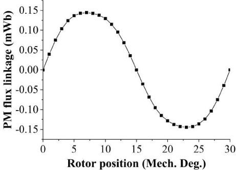
PM flux linkage of the FSCPM.

Back EMF wavefoems of FSCPM, (a) waveform, and (b) harmonic analysis.

Inductance of the FSCPM.
Cogging torque is resulted by the interaction of PMs, stator slots and rotor slots, which can bring torque ripple, vibration, noise, and affect the machine dynamic performance. The co-energy method is used for the calculation of cogging torque. After obtaining cogging torque of single phase FSCPM, the three cogging torque waveforms of different phases are compared in Fig. 12. As shown, the magnitude of a single phase cogging torque is about 0.3 Nm while the magnitude is about 0.25 Nm for three phase cogging torque. It can be seen that the main order for one phase cogging torque is the 2 times one, and the main order for three phase cogging torque is the 6 times one, which can be verified by using the harmonics order analysis method. For the cogging torque reduction, the 6th order harmonic cogging torque needs to be reduced at first, since it is the main component among the cogging torque.

Cogging torque of FSCPM.
The torque, power factor, and loss are essential to evaluate the performance of PM machines. To calculate motor performance, the d-axis current equals zero is adopted, as there is no reluctance torque and only the PM torque works. Figure 13 shows the EM torque at the rated state with the variation of rotor position. Similar to the calculation method for cogging torque, the overall torque is obtained by adding three different phase electromagnetic torque together. It can be seen that the average torque is about 0.7 Nm, and the peak to peak torque is nearly 0.6 Nm which is almost equal to the cogging torque. When compared the electromagnetic torque waveform and cogging torque waveform, it can be seen that the main torque ripple is resulted by the cogging torque. And the cogging torque needs to be reduced for achieving low ripple output torque. Figure 14 shows the electromagnetic torque with the variation of current density. As shown, the relationship between the electromagnetic torque and current density is linear. Therefore, it has the potential to be used in the high-performance application with higher current density. Figure 15 shows the power factor of the FSCPM. As shown, the power factor decreases with the increase of the torque. The power factor is about 0.6 at the rated state, which is much higher than that of a conventional CPM with SMC cores.

EM torque of FSCPM at the rated state.

EM torque of FSCPM with variation of current density.

Power factor of the FSCPM.

Core loss with variation of speed and torque.
Because of the high working frequency of FSCPM developed in this paper, the accurate performance analysis depends on the accurate core loss analysis. For the core loss analysis in FSCPM, the effect of rotational core loss should be considered. In this paper, the core loss loop for some typical parts in the stator claw pole are calculated. The coefficients of accurate core loss calculation results to alternating core loss calculation results has been obtained. Then, these coefficients are adopted for quick core loss calculation. By changing the speed and applied current density, the core loss with variation of torque and speed is illustrated in Fig. 16. In the PM machines, the maximum torque is determined by the maximum applied current below the rated speed, and above the rated speed. The DC voltage determines how high the torque and the power of FSCPM that can achieved. Figure 17 shows the DC voltage map of FSCPM with the variation of torque and speed. Efficiency map can show accurate operation state of FSCPM, it can show the efficiency at different operation state. To obtain the efficiency map, the efficiency at different states should be calculated first. The core loss has obtained in Fig. 16. It can be seen that the maximum efficiency is located above the speed of 1000 rpm and between the torque of 0.3 Nm to 0.95 Nm. The maximum efficiency is about 0.85.

Voltage with variation of speed and torque.

Efficiency with variation of speed and torque.
Since the cogging torque can bring a great number of drawbacks to PM machines. The cogging torque of FSCPM is quite high as illustrated in Fig. 12. Thus, it is necessary to reduce the cogging torque. For the cogging torque reduction, there are many methods, such as the combination of number of stator slots and rotor poles, rotor pole pairing, and rotor pole skewing. In this paper, as FSCPM is a special kind of transverse flux machine, it is different with the traditional PM machines, the number of stator slots equals the rotor poles, and the cogging torque will be reduced with the increase of number of rotor pole. However, the average electromagnetic as well as the power factor will be reduced with the increase of number of rotor pole as well. In this paper, the rotor pole skewing is selected for the cogging torque reduction.

Rotor structure for FSCPM, (a) initial rotor and (b) 3 segment rotor.
If the rotor is skewed, the resultant cogging torque of FSCPM can be calculated by,

PM flux with the change of skewing angle.

Cogging torque for FSCPM with the change of skewing angle.
For FSCPM, the ideal skewing angle is about 2.5 degrees in mechanical. However, for the developed FSCPM, the cogging torque of 12th harmonic order is high as well. The effective skewing angle will be slightly different from the calculated skewing angle. Figure 19 shows the rotor structure for FSCPM. By using 3D-FEM, the PM flux and cogging torque of FSCPM with the change of skewing angle can be obtained, as shown in Figs 20 and 21. It can be seen that the PM flux linkage will be reduced with the increase of the skewing angle, For the cogging torque, at the determined skewing angles, the cogging torque can achieve its minimum value. In this paper, the performance of FSCPM with the initial rotor, 3 segments with skewing angle of 1.25 degrees and 2.5 degrees are analyzed, as shown in Figs 22 to 25. It can be seen that the cogging torque of FSCPM with the rotor of 3 segments (2.5 degrees) is the lowest one. This design will also bring the machine with lowest torque ripple but lowest average torque. It can be obtained that the PM flux will be shifted when the skewing angle increases, and the FSCPM with the rotor segments (1.25 degrees) may be a good design for considering low torque ripple, cogging torque and high average torque.

Cogging torque for FSCPM with three different rotor design.

PM flux for FSCPM with three different rotor design.

EM torque for FSCPM with three different rotor design.

Overall comparison of FSCPM with three different rotor designs.
In this paper, a novel FSCPM with SMC cores was proposed to integrate the merits of both FSPMM and CPM with SMC cores. It can be seen that the proposed FSCPM has high torque ability, high power factor, high efficiency and good mechanical robustness. Based on the 3D FEM, the main dimensions of this machine were optimized, and the optimal parameters and motor performance were obtained. Moreover, for the reduction of cogging torque and torque ripple, its rotor was divided into 3 segments and the optimal skewing angle was obtained. The proposed FSCPM can be a good candidate for applications requiring high performance motor drives. In future work, more factors will be investigated in the optimization process, and several optimization methods, such as multilevel methods, will be considered to improve the performance of the FSCPM.
Footnotes
Acknowledgement
This work was supported in part by the Natural Science Foundation of Hebei Province under Project E2019202220, in part by National Natural Science Foundation of China under Project 51877065 and 52007047.