



Abstract
This paper presents a nonlinear iterative magnetic equivalent circuit (MEC) model for a novel counter-rotation dual-rotor axial flux permanent magnet synchronous machine (CRDR-AFPMSM). The proposed machine mainly consists of two rotors with opposite rotation directions, two sets of concentrated windings and a stator core sandwiched in between the two rotors. The model takes into account of the nonlinear characteristics of the saturable permeance in the stator core, and the permeance matrix is updated by an iterative procedure to accurately illustrate its nonlinear feature. The air gap flux density, back electromotive force (EMF) and torque are predicted by the model. Based on the nonlinear model, the thickness of the stator yoke is determined. All of the results obtained by the proposed model match with finite element analysis (FEA) results closely, thus the validity of the proposed MEC model is verified.
Keywords
Introduction
Counter-rotation propellers (CRP) are widely used as the propulsion parts of underwater vehicles (UV). Compared to using single propeller, the UV with CRP is easier to get strong and stable thrust, and also higher propulsive efficiency [1]. To make the two propellers rotate toward opposite directions, the traditional non-direct drive method is utilizing a machine with a planetary gear unit for power splitting. Obviously this method has a large mechanical loss [2]. The simplest direct method is using two machines to drive the two propellers. However, the scheme is also inefficient and takes much space. A new type radial flux machine with counter-rotation dual rotors has been widely used as the propulsion part of the UV[3,4]. The dual-rotor radial flux machine have less complicated structure and properly higher torque density than independent conventional single-rotor machines. However, the asymmetry of the radial structure results in unsatisfactory electromagnetic performance, such as two unequal output torques and large torque fluctuations, and it increases much difficulty for the control of the machine. The opposite-rotation dual-rotor axial flux permanent magnet synchronous machine (CRDR-AFPMSM) can efficiently solve the above problem.
Compared with radial flux machines (RFM), axial flux machines (AFM) enjoys many distinct advantages such as higher power-to-weight ratio, more compact structure and stronger overload capacity [5,6]. So AFMs have been widely used in wind turbines, flywheel energy storage system, hybrid and electric vehicles and other applications requiring high power density [7]. AFMs can be divided into varies types according to their different topological structures. The single-stator double-rotor (SSDR) AFPMSM is a representative type of AFPMSMs. This kind of machines adopt rotor-stator-rotor structure and the two rotors rotate toward the same direction. According to the relative positions of the two sets of PMs, the machines are divided into NN structure and NS structure, which is shown in Fig. 1. The main magnetic flux of SSDR AFPMSMs either travels axially through the stator or circumferentially in the stator yoke. The machine in this study has a similar structure to the above-mentioned machines, but its dual rotors rotate toward opposite directions.
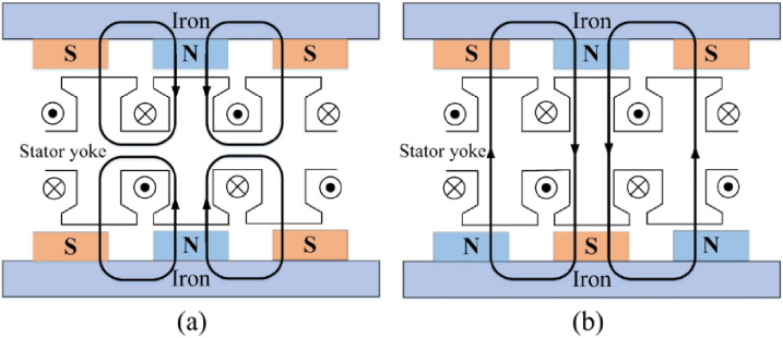
Schematic representation of SSDR AFPMSMs. (a) NN structure; (b) NS structure.
Due to the special structure of the AFPMSM, 3D FEA is always applied to study the magnetic performance. The AFPMSM can also be considered as several linear machines and each linear machine is analyzed by a 2D model [8]. Either 3D FEA or 2D FEA provides accurate results, but they are time consuming and can hardly be used in machine initial design and optimization procedures where several parameters change in wide ranges [9]. Analytical methods try to find out closed form expressions for magnetic fields in a machine [10,11]. Although they are usually simpler and more effective in many complex configurations, they seldom model the slot effect and magnetic flux leakage.
The MEC method is based on permeance network that represents the machine geometry parameters. It has been improved steadily in recent years and now integrates many advantages portrayed by other methods. The nonlinear MEC method considers local saturation of the stator core, so it provides more accurate flux density predictions [12,13]. Combined with other analytical methods such as conformal mapping and the analytical method based on Maxwell’s equations, nonlinear MEC models represent better alternative to time-consuming FEA, especially in initial stage of machine design [14]. The capability of modeling leakage fluxes has been included to some MEC methods, resulting in better estimations of flux distributions [15]. By calculating the equivalent permeances of teeth, the MEC model can get accurate results without ignoring complex slot shapes [16]. MEC models are also established to analyze final machine design for performance predictions [17,18].
The main contribution of this paper is developping a nonlinear MEC model of the CRDR-AFPMSM which is sufficiently accurate and can be used in design process. The topological structure of the machine is similar to SSDR AFPMSMs. However, as the relative position of the two rotors changes, NN structure and NS structure appear alternately. The relevant electromagnetic performances of the machine under the two totally different conditions are studied by proposed model. For electromagnetic torque calculation, the proposed model shows excellent ability to predict them accurately and efficiently. Moreover, an iterative algorithm aimed at optimally designing the thickness of the stator yoke and increasing the efficiency of the machine is presented, which is seldom mentioned in other non-linear MEC models.
This paper is organized as follows. The structure of the prototype machine and three magnetic circuit models are introduced in Section 2. Section 3 introduces the complete MEC model and the proposed iteration procedure. In Section 4 the proposed model is used to predict the performance of the machine, including flux density distributions, back-EMF and torque. Section 5 introduces the design procedure of the stator yoke thickness and other main parameters of the machine using the proposed model. Finally, conclusions are given in Section 6.

Schematic representation of CRDR-AFPMSM. (a) Structure of the machine; (b) Two sets of independent concentrated windings.
Structure of the machine
Figure 2 illustrates the schematic view of the proposed CRDR-AFPMSM and its windings. The machine mainly consists of the following several components: Two identical but independently rotating rotors with surface mounted PMs. The dual rotors are set to rotate toward opposite directions. Single stator yoke. The stator yoke is sandwiched in between in the dual rotors and has been slotted symmetrically on both sides. Two sets of concentrated windings. These windings are embedded into the slots of the stator and provide the magnetic motive forces (MMF) moving toward opposite directions in the two equal-thickness air gaps. Thus, the two rotors can rotate at the identical speed and power in opposite directions.
Magnetic circuit model
Like the traditional quasi 3-D analytical model of AFPMSMs, the CRDR-AFPMSM can also be divided into several segments and each segment is seen as a linear machine of infinite length. The total performance of the machine can be expressed as:
As is shown in Fig. 3, with the change of the relative location of the two rotors, NN magnetic circuit and NS magnetic circuit appear alternately. When the PMs on the two rotors are not aligned in axial direction, transition magnetic circuit will appear in the machine.
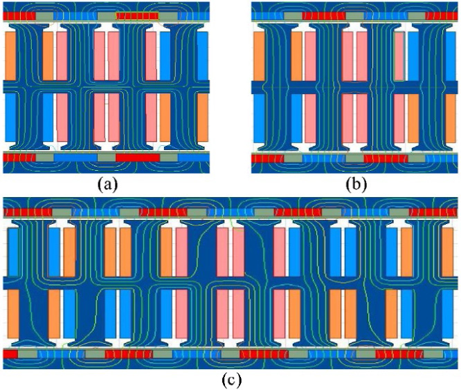
No-load flux path (a) NN structure circuit; (b) NS structure circuit; (c) Transition structure circuit.
The machine is divided into N
d
(=5) layers in the radial direction and each layer can be equivalent to a linear machine with a thickness of L. The division method is illustrated in Fig. 4.
In order to avoid the strong coupling between the stator and rotors, the MEC of the CRDR-AFPMSM can be divided into three parts, namely rotor part, air gap part and stator part. The permeability of the rotor and air gap parts are constant. However, the permeability of the stator part are all nonlinear due to the fact that the permeability of the stator core will change as the flux density varies.
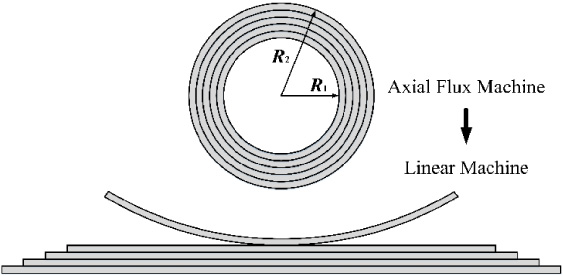
The method of converting a axial flux machine to several linear machine.
The calculation formula of magnetic permeances is
The MEC of rotor is shown in Fig. 5. In the rotor part, the permeability of back iron is assumed to be constant. The rotor PM is modeled as a magnetomotive force (MMF) source with magnetic permeance and they are respectively given by
For the rotor part, the model of flux leakage determines the accuracy of results. The flux leakage in rotor part mainly consists of two parts: the flux leakage between the PM and the back-iron, and the flux leakage between adjacent poles.
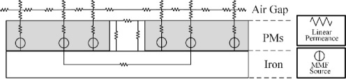
MEC model of rotor part.
In the Fig. 6, the thickness of the flux tube l
1 is the minimum of the air gap length and half of the inter-polar length, as
For the flux leakage permeance between adjacent poles, the flux tubes are located in the air gap and the air area between adjacent PMs.
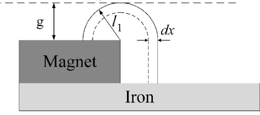
The flux leakage between the PM and the back-iron.
According to Fig. 7(a), the flux leakage permeance in the air gap can be calculated from
The flux path in the air area between adjacent PMs is shown in Fig. 7(b). PMs in the machine are all divided into equally and adequately parts (in this paper, the PM is divided into 30 parts) in the axial direction to realize accurate calculation of flux leakage permeance.
For the ith segment, its leakage permeance can be calculated by
Finally, the sum of flux leakage permeance of each unit forms the flux leakage permeance in between adjacent PMs.
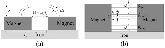
The flux leakage between adjacent poles. (a) The flux leakage in the air gap; (b) The flux leakage in the air area between adjacent PMs.
In order to improve the accuracy of the MEC model, this paper take the local stator core saturation into account. The stator tooth is divided into several parts according to the structure of the tooth tip [16]. Some permeance models for different shapes and different flux directions in the tooth tip are illustrated in Table 1.
Permeances used in stator teeth
Permeances used in stator teeth
The MMF generated by 3-phase windings can be expressed as
The MEC model of stator is shown as Fig. 8.
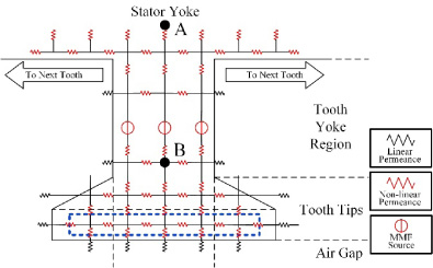
MEC model of stator.
In this MEC model, the stator part and rotor part are independent. In order to calculate the flux densities in axial and tangential direction simultaneously, the air gap model is divided into two floors. The permeances in the air gap are all calculated by (3). Figure 9 shows the partial model of the air gap.
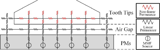
MEC model of air gap.
The complete MEC model is shown in Fig. 10. The MMF matrix can be obtained by
In the MEC model, an iterative procedure illustrated in Fig. 11 is used to obtain the accurate permeability of saturable permeances.

Complete MEC model.

Flowchart of the nonlinear iteration process.
In order to determine the permeance network and calculate the MMF matrix, an initial value is assigned to the relative permeability of stator core and the value is usually taken as 8000. Input the flux generated by PMs and windings, then the MMF of all nodes can be obtained. The flux density values of each nonlinear segment can be calculated by
In this section, the accuracy of non-linear MEC model is examined. The air gap flux density distribution obtained by proposed model is showed. Then based on the flux density in the air gap, the back-EMF and average torque of the machine are calculated.
Flux density
In order to verify the accuracy of the proposed nonlinear MEC model, the characteristics of the studied machine obtained by the proposed model, are evaluated and compared with those issued from 3D FEA. In the condition of rated-load operation, the axial flux density and tangential flux density in the middle of the air gap under the NS magnetic circuit condition mentioned above are shown in Fig. 12. Figure 13 shows the absolute value of average flux density distributions around node A and B shown in Fig. 8 under the same condition. The results obtained from proposed model conform well to those obtained from 3D FEA.
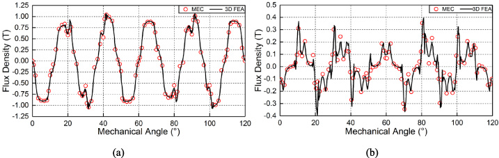
Comparison of flux density in air gap under rated-load condition. (a) Axial direction; (b) Tangential direction.
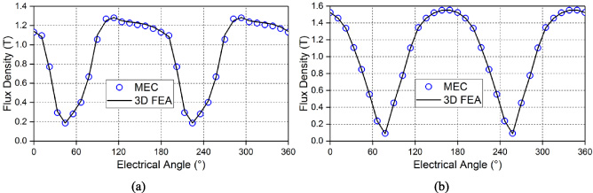
Comparison of flux density in stator core under rated-load condition. (a) Node A; (b) Node B.
The nodes in the boxed area shown in Fig. 8 are selected to indicate the difference between nonlinear MEC method and linear MEC method at a certain moment. Figure 14 shows that considering the saturation of the core will greatly reduce the error of results.
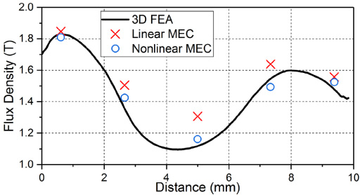
Comparison of flux density in the tooth.
The back-EMF of each phase can be obtained from the distribution of flux linkages. The formula is
Figure 15 shows the comparison of back-EMF of phase A obtained by proposed MEC model and FEA under no-load condition, the initial relative position of two rotors is in NS magnetic circuit and the results are in good agreement. According to the calculation results, the variation of RMS value of back-EMF obtained by non-linear MEC model is only 2.81% compared with that obtained by 3D FEA.

Comparison of back-EMF of phase A.
With the help of air gap flux density, the instantaneous torque of the machine can be calculated. Figure 16 shows the rated-torque of the machine.
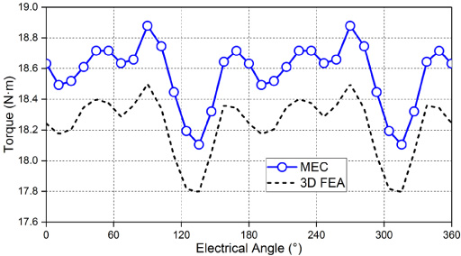
Comparison of instantaneous torque under rated-load condition.
As is shown in Fig. 17, the average torques of the machine excited by the rated current with different PM length are calculated by MEC model and FEA. In the condition that the pole arc to pole pitch is 0.7, the average torque calculated by non-linear MEC is 1.87% higher by than that obtained by 3D FEA. It is not difficult to get from the figure that the average torque increases as the PM length increases. However, another conclusion we can get from the figure is that the torque increasing rate would decrease. So in order to obtain the suitable operating efficiency, the PM length should not be too long.
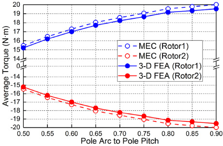
Comparison of average torque for variation of PM length.
In order to avoid saturation and consequent problems as well as efficiently utilizing the iron material, an iterative procedure illustrated in Fig. 18 is also presented to determine the stator yoke thickness and it ensures that the stator yoke can magnetically operate under the knee point of the B-H curve.
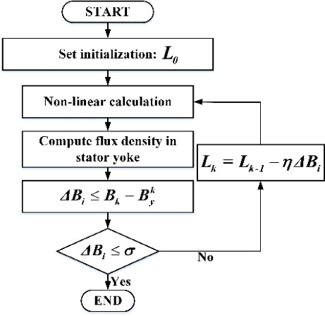
Flowchart of the determination of the stator yoke thickness.
Under the initial condition, the stator yoke thickness L
0 is large enough. In each step of the iteration procedure, the stator yoke thickness gets updated by the following formulas:
The maximum flux densities in the stator yoke under NN structure circuit and NS structure circuit are shown in Fig. 19 respectively. It is found from the figure that the interference of windings tends to adjust the flux density distribution in the stator yoke, and this phenomenon is more serious in NN structure circuit. The thickness of stator yoke is determined to be 5 mm by comprehensively considering the flux density in stator yoke and the mechanical strength of the machine.
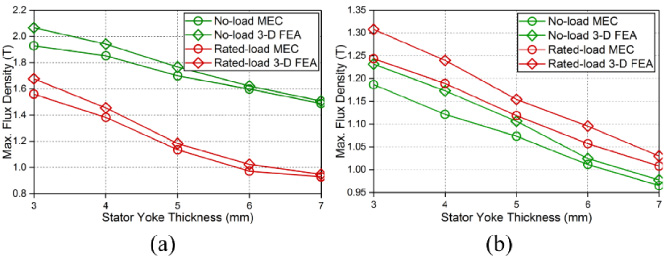
Maximum flux density in the stator yoke. (a) NN structure circuit; (b) NS structure circuit.
Finally, the main parameters of the prototype machine are shown in Table 2.
Specific parameters of the CRDR-AFPM
In this paper, a counter-rotation double-rotor AFPMSM has been proposed. The machine has a similar topological structure to the single-stator double-rotor AFPMSM, which have either a NN structure or a NS structure. But in the operating process of the CRDR-AFPMSM, the NN magnetic circuit and NS magnetic circuit in the machine appear alternately. To effectively verify the design parameters and electromagnetic characteristics of the CRDR-AFPMSM, a nonlinear iterative MEC model considering the saturation of iron is proposed in this paper. In the meantime, the flux leakage and slot effect are also considered in the MEC model.
The proposed model can be used to obtain accurate flux density distributions, phase back-EMF and torque. Based on the MEC model, the considerations toward more practical designing of the prototype machine have been analytically proposed. The flux density in the stator yoke are predicted and analyzed by the MEC model, and the suitable stator yoke thickness is then determined. In addition, all the above results are compared with the results obtained from 3D FEA and they are all in great agreement, thus the correctness of the proposed model is validated.
Footnotes
Acknowledgement
This work was supported by the Strategic Priority Research Program of the Chinese Academy of Sciences under Grant XDA22000000, the National Natural Science Foundation of China under Grant 51807194, Zhejiang Basic Public Welfare Research project under Grant LGG18E070007 and the Ningbo Science and Technology Innovation Key Projects under Grant 2018B10068.